Schäfter+Kirchhoff SK1024VSD User manual

Instruction Manual SK1024VSD shared_Titel_ML.indd
SK1024VSD
Monochrome Line Scan Camera
1024 pixels 14 x 14 µm², line frequency up to 27 kHz
Instruction Manual
SK1024VSD
3
2
4
1
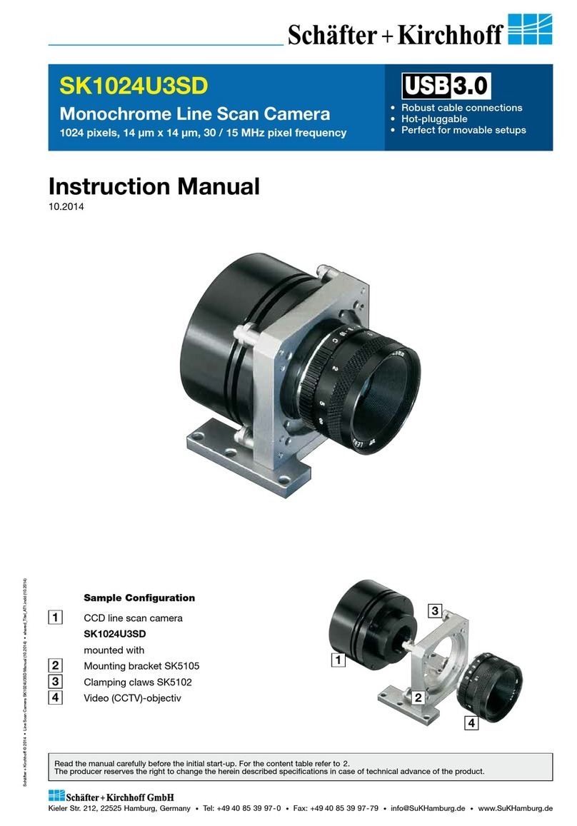
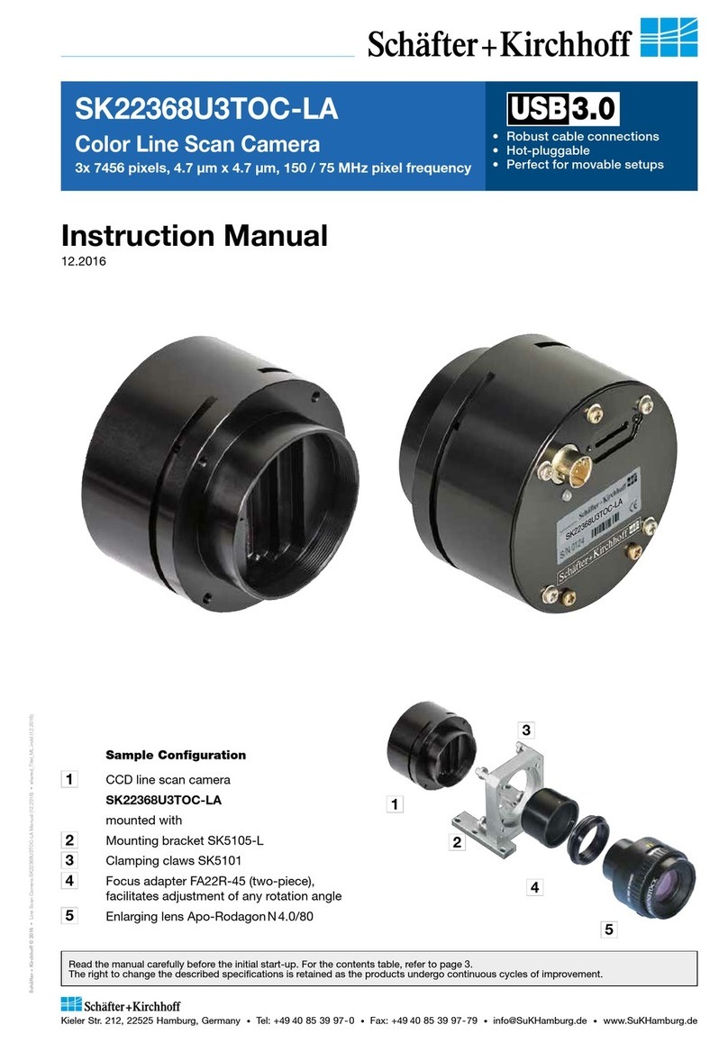
Sample Configuration
1CCD line scan camera
SK1024VSD
mounted with
2Mounting bracket SK5105-L
3Clamping claws SK5101
4Video (CCTV)-objectiv
1.0
0.0
400 600
Wavelength (nm)
800 1000
Spectral
range
Line scan camera with large dynamic range and 27 kHz maximum line rate,
anti blooming and integration control.

Instruction Manual SK1024VSD shared_Hinweise.indd
2
Instruction Manual SK1024VSD © 2019-02 E
How to Use this Instruction Manual
Electricity Warning
Assembly and initial operation of the line scan camera must be carried out under dry
conditions.
Do not operate the camera if you notice any condensation or moisture in order to avoid danger
of a short circuit or static discharge!
Risk of High Power Lighting
According to the application, laser or high power LED light sources might be used. These can
affect your eyesight temporarily or even cause permanent damage to the eyes or skin.
Do not look directly into the light beam!
Mechanics Warning
Ensure that the motion device and the scan way is free to move and that no obstacles are in
the way.
Do not place any part of the body in the way of moving parts!
Line scan cameras are mostly used in combination with a motion device such as a translation
stage, a conveyer or a rotational drive, as well as with high intensity light sources.
For assembly close down these devices whenever possible. Beyond that, please consider the
following warnings:
Safety Warnings
Please read the following sections of this Instruction Manual before unpacking, assembly or use
of the Line Camera System:
The safety warnings on this page
Introduction to the system, page 4
Installation and Setup, page 7
Keep this Instruction Manual in a safe place for future reference.
!

Instruction Manual SK1024VSD shared_Contents.indd
3
Instruction Manual SK1024VSD © 2019-02 E
Contents
How to Use this Instruction Manual 2
Safety Warnings 2
Contents 3
1 Introducing the SK1024VSD Line Scan Camera �������������������������������������������������� 4
1.1 Intended Purpose and Overview 4
1.2 System Setup at a Glance 5
1.3 Computer System Requirements 6
1.4 SK1024VSD Line Scan Camera - Specifications 6
2 Installation and Setup ������������������������������������������������������������������������������� 7
2.1 Mechanical Installation: Mounting Options and Dimensions 7
2.2 Electrical Installation: Connections and I/O Signals 8
2.3 GigE Connections and Software Installation 9
GigE Network Integration for Standard GigE Network Adapters 9
2.4 SkLineScan Software Installation (Optional) 11
SkLineScan Installation 11
SkLineScan Start-up 11
Camera Setup 11
Initial Function Test 11
3 Camera Control and Performing a Scan �������������������������������������������������������� 12
3.1 Software: SkLineScan 12
Function Overview: SkLineScan Toolbar 12
Visualization of the Sensor Output 13
3.2 Adjustments for Optimum Scan Results 14
Lens Focussing 14
Sensor Alignment 15
Gain/Offset Adjustment 15
Shading Correction 16
Optimum brightness adjustment, Integration Time 17
Synchronization of the Image Acquisition with the Feed Rate of the Object 18
Synchronization Modes 20
3.3 GigE Vision Device Feature List (Gen<i>Cam compliant) 22
4 Advanced Camera Control Functions ����������������������������������������������������������� 24
4.1 Camera Control by Commands 24
Set Commands 25
Request Commands 25
4.2 Advanced Synchronization Control 26
Advanced Trigger Functions and Sync Control Register (SCR) Settings 26
Example Timing Diagrams 27
5 Sensor Information �������������������������������������������������������������������������������� 28
Glossary 30
CE-Conformity 33
Warranty 33
Accessories 34

Introducing the SK1024VSD Line Scan Camera
Instruction Manual SK1024VSD shared_Introduction_GigEV_ML.indd
4
Instruction Manual SK1024VSD © 2019-02 E
The SK line scan camera series is designed for a wide
range of vision and inspection applications in both
industrial and scientific environments.
The SK1024VSD GigE VisionTM line scan camera uses
the Gigabit Ethernet communication protocol and is
100% compliant with the GigE VisionTM specifications
and the Gen<I>CamTM standard.
GigE Vision allows for fast image transfer using low
cost standard cables up to distances of 100m. With
GigE Vision, hardware and software from different
vendors can interoperate seamlessly via the GigE
connections. The camera is connected to a computer
either via the GigE socket directly or through a Gigabit
Ethernet switch.
When taking the camera into operation the first time
the Schäfter+Kirchhoff SkLineScan®program is recom-
mended. Once the camera driver and the SkLineScan®
program have been loaded from the SkLineScan CD
or zip-file then the camera can be parameterized. The
parameters, such as integration time, synchronization
mode or shading correction, are permanently stored in
the camera even after a power-down or disconnection
from the PC.
The oscilloscope display in the SkLineScan®program
can be used to adjust the focus and aperture settings,
for evaluating field-flattening of the lens and for orien-
tation of the illumination and the sensor, see 14.6 GigE
Connections and SkLineScan Software Installation (p.
69).
The Schäfter + Kirchhoff GigE Vision line scan
cameras implement a superset of the Gen<I>Cam™
specification which defines the device capabilities.
The settings made in the SkLineScan®program are
automatically provided to the device feature liste of any
Gen<I>Cam compliant software.
The Gen<I>CamTM standard provides a generic
programming interface for all kinds of cameras and, no
matter what features they implement, the application
programming interface (API) always remains the same.
The Gen<I>CamTM standard consists of multiple
modules relevant to the main tasks to be solved:
GenApi: for configuring the camera
Standard Feature Naming Convention (SFNC): recom-
mended names and types for common features
GenTL: transport layer interface, for grabbing images
For more information on the GigE VisionTM specifi-
cation, see:
https://www.visiononline.org/vision-standards-details.
cfm?type=5
or the Gen<I>CamTM standard:
http://www.emva.org/standards-technology/genicam/
1 Introducing the SK1024VSD Line Scan Camera
1.1 Intended Purpose and Overview
CCD line scan camera
2Power supply
3Illumination
Software Gen<i>Cam
-compliant, eBus driver
GigE switch
14
5
PC or
Notebook
with GigE
GigE interface for transmission
of video and control data over
distances up to 100 m
421
3
Application:
Parallel
acquisition
using a
GigE switch
4
2
1
5
Introducing the SK1024VSD Line Scan Camera
Instruction Manual SK1024VSD shared_Introduction_GigEV_ML.indd
5
Instruction Manual SK1024VSD © 2019-02 E
1.2 System Setup at a Glance
red: SK1024VSD scope of delivery
blue: accessories for minimum system configuration
black: optional accessories
For accessory order details see Accessories (p. 34).
Motion unit
with encoder
Synchronization cable
Power supply cable
Gigabit Ethernet cable
Computer
Power supply
unit
Schäfter+Kirchho
SkLineScan®adjustment
and control software
3rd party software
that supports the
GEN<i>CAMTM standard
Line scan camera
Clamping claw
Mounting bracket
Optics (e. g. lens,
focus adapter, tube
extension ring)

Sensor category CCD Monochrome Sensor
Sensor type IL-P3-1024
Pixel number 1024
Pixel size (width x length) 14 x 14 µm2
Pixel spacing 14 µm
Active sensor length 14.3 mm
Anti blooming x
Integration control x
Shading correction x
Threshold detection -
Line synchronization modes Line Sync, Line Start, Exposure Start, Exposure Active
Frame synchronization x
Pixel frequency 30 / 20 MHz
Maximum line frequency 27 kHz
Integration time 0.01 ... 20 ms
Dynamic range 1:2000 (rms)
Spectral range 400 ... 1000 nm
Video signal monochrome 8/12 Bit digital
Interface GigE Vision
Voltage +5V, +15V
Power consumption 3.0 W
Casing 65 mm x 65 mm x 71.1 mm (Case type BG1)
Objective mount C-Mount
Flange focal length 17.53 mm
Weight 0.3 kg
Operating temperature +5 ... +45°C
Introduction
Instruction Manual SK1024VSD shared_SystemRequirements_Specs_ML.indd
6
Instruction Manual SK1024VSD © 2019-02 E
1.3 Computer System Requirements
1.4 SK1024VSD Line Scan Camera - Specifications
Introduction
• Intel Pentium Dual Core or AMD equivalent
• RAM min. 4 GB, depending on size of acquired
images
• High-performance video card, PCIe bus
• Operating Systems:
Windows 7 / 8.1 / 10 (64 or 32-bit) or
Linux kernel 3.13 or higher
• CD/DVD drive for software installation.
Network Adapter:
• Any Gigabit Ethernet network adapter as a card
or on the motherboard is suitable. For the best
performance, a network interface card (NIC) with
Intel PRO/1000 chip is recommended.
• PCIe adapters outperform PCI adapters.
• Network adapters that support Jumbo Frames
outperform adapters with fixed packet-size frames.

Installation and Setup
Instruction Manual SK1024VSD shared_Installation-Mechanic_Axx-BGx_ML.indd
7
Instruction Manual SK1024VSD © 2019-02 E
2 Installation and Setup
2.1 Mechanical Installation: Mounting Options and Dimensions
Casing type BG1
Mounting Options
• The best fixing point of the camera is the collar for
the mounting bracket SK5105-L (available as an
accessory).
• Four threaded holes M3x 6.5 mm provide further
options for customized brackets.
• The length and weight of the optics might be beyond
the capability of the standard mounting bracket
SK5105-L. For this purpose, a second mounting
bracket type SK5105-2L to hold the tube extension
ring(s) is more appropriate.
Optics Handling
• If the camera and the optics are ordered as a kit,
the components are pre-assembled and shipped
as one unit. Keep the protective cap on the lens
until the mechanical installation is finished.
• If you must expose the sensor or lens surface,
ensure the environment is as dust-free as possible.
• Gently blow off loose particles using clean
compressed air.
• The sensor and lens surfaces can be cleaned with
a soft tissue moistened with water or a water-based
glass cleaner.
Mounting bracket SK5105-L
Mounting system SK5105-2L
for cameras with a tube
extension > 52 mm
Clamping set SK5101
Set of 4 pcs. clamping claws
incl. screws
66
10 10
36
M3
Ø3.3
6
50.3
41.7
Ø 47.5
50
20
16.5
3.5
6.5
Ø4.3
15 M4
1/4’’ 20G
40
63
70
6
36
Ø 47.5
70
3.5 31.5
25
10
3.5
70
63
40
1/4’’20G
M4
Ø4.3
Hex socket head screw
DIN 912–M3x12
Clamping claw
Pixel 1
M3 (4x)
depth 6.5 mm
65
65
58
41.7
Ø65
Ø47.5
C-Mount 71.1
BG1 Lens mount: C-Mount
Seat for bracket: Ø47.5 mm
Flange focal length: FFL = 17.5 mm
CCD-Sensor
2.5 6
4 23.5 FFL
11.1
50/M3/4x90°

1Power +5 V, +15 V Hirose series 10A, male 6-pin
Total power: 3.0 W
Pin Signal Pin Signal
1+15 V 4+5 V
2+15 V 5GND
3+5 V 6GND
2
1
3
4
5
6
7
8
9
10
1112
2
1
3
4
5
6
Power Cable SK9015.xMF
Use this cable to feed external supply voltage into socket 1.
Connectors:
Hirose plug HR10A, female 6pin (camera side)
Lumberg SV60, male 6-pin connector (for supply voltage)
Length 1.5 m (standard) or 0.2 m
Power Supply Unit PS051515
Input: 100-240 VAC, 0.8 A, 50/60 Hz, IEC 320 C14 coupler
(for IEC C13 power cord)
Output: +5V DC, 2.5 A / +15 V DC, 0.5 A / -15 V DC, 0.3 A
Cable length 1 m, with Lumberg connector KV60,
female 6-pin
(for power cable SK9015.x or SK9016.x)
3
1
2
Installation and Setup
Instruction Manual SK1024VSD shared_Installation-Electric_GigE+V_ML.indd
8
Instruction Manual SK1024VSD © 2019-02 E
2.2 Electrical Installation: Connections and I/O Signals
External Synchronization Cable SK9024.x
Use this cable to feed external synchronization
signals into socket 2.
Connectors:
Hirose plug HR10A, female 12pin (camera side)
Phoenix 6 pin connector incl. terminal block (for
synchronization signals)
Length 3 m or 5 m. Other lengths on request.
Network Cable CAT6.x
For connecting socket 3with the PC Ethernet
interface. Both ends with RJ45 connectors.
• For the SK1024VSD line scan camera-data transfer and camera control is provded by the Gigabit Ethernet
interface 3. Use a CAT6 twisted-pair cable to connect the camera to a PC; the maximum cable length is
100 m.
• The operating power must be supplied by an external source using socket 1
• If you want to operate the camera in FREE RUN trigger mode, the connections are complete with the CAT6
Ethernet cable and the connection to an external power supply.
• For any kind of synchronized operation, the external trigger signal(s) must be wired to socket 2as well. A
frame-synchronization signal and two separate line-synchronization signals can be handled. The various
trigger modes are described fully in section Synchronization of the Image Acquisition with the Feed Rate
of the Object (p. 18)
2
1
3
4
5
6
7
8
9
10
1112 2
1
3
4
5
6
Pin Signal *)
1GND
8FrameSync IN
10 LineSync A IN
6LineSync B IN
2I/O Connector Hirose series 10A, male 12-pin
*) Signal Specification
(TTL) Max. input frequency 16.5 MHz
Input voltage,
absolute max. range
min -0.5 V
max 7.0 V
Input voltage max. low 0.99 V
Input voltage min. high 2.31 V
Input current 10 µA
Installation and Setup
3Data
RJ-45 connector for Gigabit Ethernet cable
Status indicators
Network connection speed Network activity
off no connection,
10 Mbyte/s connection, or
100 Mbyte/s connection
on 1 Gbyte/s connection
off no connection
on connected
flash
light
data is being
transmitted or
received
Accessories (see also Acessories (p. 34):

Installation and Setup
9
Instruction Manual SK1024VSD shared_Installation-Software_GigEV.indd
Instruction Manual SK1024VSD © 2019-02 E
Installation and Setup
2.3 GigE Connections and Software Installation
GigE Network Integration for Standard GigE Network Adapters
The SK1024VSD GigE VisionTM line scan camera uses the Gigabit Ethernet communication protocol, which is 100%
compliant with the GigE VisionTM specifications and the Gen<I>CamTM standard.
The Gen<I>CamTM standard provides a generic programming interface for all kinds of cameras and, no matter what
features they implement, the application programming interface (API) always remains the same.
For software and Network Interface Controller (NIC) driver installation, the following possibilities apply:
1. The Gen<I>CamTM compliant 3rd party software you want to install includes a particular filter driver for
the NIC.
Install the software package. Commonly this will also cover the driver installation.
2. The 3rd party software does not include a NIC filter driver, and your NIC has an INTEL PRO/100 chip.
Install the Pleora eBUS Optimal Driver.
3. The 3rd party software does not include a NIC filter driver, and your NIC has a different chip.
Keep the manufacturer driver and follow the instructions in the next section.
The Pleora eBUS driver installation tool is available from Schäfter + Kirchhoff either on CD or as download from
http://www.sukhamburg.com/supporte.html
a) Subnet Setting
The GigE Vision camera has an enforced static IP
address. The NIC IP address must be part of the same
subnet otherwise the camera is not accessible.
An example of a persistent IP address that is assigned
to a class B network is:
Persistent IP = 169.254.35.10
Subnet Mask = 255.255.0.0
Default Gateway = 0.0.0.0
This section is relevant for systems with a standard NIC (not INTEL PRO /1000) in combination with the
manufacturer driver (case 3).
B
A

Installation and Setup
Instruction Manual SK1024VSD shared_Installation-Software_GigEV.indd
10
Instruction Manual SK1024VSD © 2019-02 E
b) Windows Firewall
a) Switch off the Windows Firewall or
b) Allow an exception:
Start > Control Panel > Open the Windows Firewall
Select the Exceptions tab
Click Add Program
The "Add a Program" dialog appears
Select the camera control program and click "OK"
Click "OK" to close the Windows Firewall dialog
c) Optimizing the Network Adapter Settings
Open the "Advanced" Properties tab Dof the Network
Adapter and enter the following values:
Jumbo Frames 9014 Bytes
Receive Descriptors 2048
Interrupt Moderation Rate extreme
Energy Efficient Ethernet OFF
Network Controller Properties: Note, the terms
can differ depending on the installed Ethernet
card and driver.
D
C
To Set the NIC IP address:
Start > Control Panel > Network Connections.
Right-click Local Area Connection and select Properties.
The Local Area Connection Properties dialog appears.
Select Internet Protocol (TCP/IP) and click Properties. The
Internet Protocol (TCP/IP) Properties dialog appears.
Enable "Use the following IP address" and enter the
following settings:
IP address: 169.254.35.10
Subnet mask: 255.255.0.0
Default gateway: leave blank
Ensure these do not conflict with an existing IP address on
another NIC. For multiple dedicated connections on the
same host PC, increment the third IP address by one for
each NIC (i.e. 36, 37, etc., subnet 255.255.255.0 - class C).
Click OK to close the Internet Protocol (TCP/IP) Properties
dialog.
Click Close to close the Local Area
Connection Properties dialog.
Your NIC is now configured for a
dedicated connection.
A
B
C
LAN Connection 4
Speed: 1.0 GBit/s
Status: Connected

Installation and Setup
11
Instruction Manual SK1024VSD shared_Installation-Software_GigEV.indd
Instruction Manual SK1024VSD © 2019-02 E
Initial Function Test
• Quit the SkLineScan startup dialog
box.
• Select "OK" in the SkLineScan
start-up dialog.
The Signal Window plotting the current
brightness versus the pixel number
indicates the correct installation.
Camera Setup
Use the Setup dialog for
• activating/deactivating a connected
GigE camera (activated device is
ticked)
• changing the IP address
• changing the pixel frequency
• setting the bit depth of the video
signal to 8 or 12-bit.
The MAC addresses are displayed for identification of each camera with the defined CamID (0, 1, …). This is
useful when several cameras with the same name are connected.
SkLineScan Setup dialog
SkLineScan Start-up
• Start SkLineScan. A start-up dialog box pops up
and displays the connected cameras that have
been automatically detected. Desktop Icon
2.4 SkLineScan Software Installation (Optional)
SkLineScan Installation
Prior to the installation, power on the PC (not the camera) and unpack the downloaded zip-file to a temporary
folder. Alternatively, if your installation medium is a CD, insert the disk into the drive.
The autostart function may launch the setup program automatically from CD. Otherwise, look for the installation
file:
SkLineScan_GEV.msi
Then start the applicable installation file manually. This will set up the Schäfter + Kirchhoff SkLineScan camera
control and adjustment tool.
This section is a quick reference for installing the SkLineScan adjustment and configuration software.
SkLineScan and the SkLineScan manual is provided for download on the Schäfter + Kirchhoff website under
http://www.sukhamburg.com/supporte.html.

Camera Control and Performing a Scan
Instruction Manual SK1024VSD shared_CameraControl(1)_SkLineScan_ML.indd
12
Instruction Manual SK1024VSD © 2019-02 E
3 Camera Control and Performing a Scan
3.1 Software: SkLineScan
This section is a brief introduction to the SkLineScan adjustment and configuration software. A more detailed
description is provided in the separate SkLineScan manual. The pdf is included in the SkLineScan installation
package or is available for download from the Schäfter + Kirchhoff website under http://www.sukhamburg.com/
supporte.html.
Detailed instructions on how to obtain optimal image data and use the data with the Schäfter+Kirchhoff
software package can be found in the SkLineScan Software Manual.
The most common functions of the line scan camera can be controlled by menu items and dialog boxes.
In the "Camera Gain / Offset Control" dialog there is a command line for entering further control commands.
Click on the desktop icon to start the SkLineScan
program.
The SkLineScan program recognizes the connected line
scan cameras automatically. The identified cameras are
shown in the start-up dialog A.
If the SK1024VSD camera is identified correctly,
confirm with "OK". The "Signal window" graphicaly
showing the intensity signals of the sensor pixels (oscil-
loscope display) will open. It is responsive in real-time
and the zoom function can be used to highlight an area
of interest. The oscilloscope display is ideally suited
for parameterizing the camera, for evaluating object
illumination, for focussing the image or for aligning the
line scan camera correctly.
Function Overview: SkLineScan Toolbar
Platzhalter für Grafiken in anderen Ebenen
New line scan. All open "Signal window" windows will be closed. [F2]
"Camera Control" dialog for parameter settings: integration time, line frequency, synchronization
mode, thresholding
Zooming in and out
New line scan. "Area Scan" windows will be closed, "Signal window" windows will remain open. [F2]
Threshold mode in new binary signal window.
"Shading Correction" dialog to adjust the white balance [Alt+ s]
"Gain/Offset Control" dialog, also for commands input [Shif+F4]
New area scan
SkLineScan: Toolbar
SkLineScan: Start-up dialog
A

Camera Control and Performing a Scan
Instruction Manual SK1024VSD shared_CameraControl(1)_SkLineScan_ML.indd
13
Instruction Manual SK1024VSD © 2019-02 E
Visualization of the Sensor Output
• Signal Window / Oscilloscope Display
The signal window plots the digitalized brightness profile as signal intensity (y-axis) versus the sensor length (x-axis)
at a high refresh rate. The scaling of the y-axis depends on the resolution of the A/D converter: The scale range is
from 0 to 255 for 8-bits and from 0 to 4095 for 12-bits. The scaling of the x-axis corresponds with the number of
pixels in the line sensor.
Platzhalter für Grafiken in anderen Ebenen
• Zoom Function
With a high number of sensor pixels, details are lost due to the limited number of display pixels. With the zoom
function you select a part of the sensor for the detailed display. The possible magnification ranges up to the repre-
sentation of the intensity signal of individual pixels.
• Window Split Function
The signal window can be divided horizontally into two areas. Use the slider Bat the top of the vertical scroll bar.
If you then use the zoom function in one frame, the selected section in the other frame will be highlighted in yellow.
Platzhalter für Grafiken in anderen Ebenen
Line scan in Signal
Window: brightness
vs. pixel number
B
Line scan in split
signal window: The
upper frame shows
an enlarged section
of the lower frame.

Camera Control and Performing a Scan
Instruction Manual SK1024VSD shared_CameraControl(2)_Adjustments-1_ML.indd
14
Instruction Manual SK1024VSD © 2019-02 E
Camera Control and Performing a Scan
3.2 Adjustments for Optimum Scan Results
•Lens focussing
•Sensor alignment
•Gain/Offset
•Shading correction
•Integration time
•Synchronization of the sensor exposure
and the object surface velocity, trigger
mode options.
Prior to a scan, the following adjustments and parameter settings should be considered for optimum
scan signals:
Start with the signal window / oscilloscope display. Any changes in the optical system or camera parameters
are displayed in real-time when using an open dialog box.
Lens Focussing
The real time Signal Window facilitates the effective focussing of the line scan camera system, even for
two-dimensional measurement tasks. For determining the correct focus, the edge steepness at dark-bright transi-
tions and the modulation of the line scan signal are the most important factors.
Adjust the focus with the aperture fully open to limit the depth of field and enhance the effects of changing the
working distance.
If the sensor is overloaded when the aperture is fully open, the easiest way to reduce the signal amplitude is to
shorten the integration time, as described in section Optimum brightness adjustment, Integration Time (p.
17).
Out-of-focus:
• Low edge steepness
• Signal peaks are blurred
• High spatial frequencies with low modulation depth
Optimum focus:
• Dark-bright transitions with steep edges
• Large modulation in the signal peaks
• High spatial frequencies with high modulation depth
steep edges
high modulation
depth
low modulation depth
low edge steepness

Camera Control and Performing a Scan
15
Instruction Manual SK1024VSD shared_CameraControl(2)_Adjustments-1_ML.indd
Instruction Manual SK1024VSD © 2019-02 E
Sensor Alignment
If you are using a linear light source, check the alignment of the light source and sensor before shading correction,
as rotating the line sensor will result in asymmetric vignetting.
Sensor and line lighting slightly twisted in
relation to each other, asymmetric vignetting
Sensor and line lighting aligned in parallel,
symmetric vignetting
Gain/Offset Adjustment
The cameras are supplied with factory-set gain/offset. Open the "Gain/Offset Control" dialog to adjust these
settings.
Platzhalter für Grafik und Text in anderen Ebenen
Adjustment principle
1. Offset
To adjust the zero baseline of the video signal, totally
block the incident light and enter "00" (volts) for
channel 1.
For a two- or multi-channel sensor, minimize any diffe-
rences between the channels by adjusting the other
Offset sliders.
A slight signal noise should be visible in the zero
baseline.
2. Gain
Illuminate the sensor with a slight overexposure in order
to identify the maximum clipping. Use the Gain slider
"1" to adjust the maximum output voltage.
For a two- or multi-channel sensor, minimize any diffe-
rences between the channels by adjusting the other
Gain sliders.
For the full 8-bit resolution of the camera, the maximum
output voltage is set to 255 and for 12-bit is set to
4095.
Offset
and gain
adjustment
for more than
one gain/
offset channel
2. Adjust the gain of channel 1.
Minimize the difference
between the channels with
the other gain controls.
1. Adjust the zero level of
channel 1. Minimize the
difference between the
channels using the other
Offset controls.
The gain/offset dialog contains up to 6 sliders for altering gain and offset. The number of active sliders depends
on the individual number of adjustable gain/offset channels of the camera. If "Coupled Gain Channels" is checked,
all channels are set synchronously with one slider.
Enter commands for advanced software functions in the 'Camera Control' field (see page 14).
Gain/Offset
Control dialog

Camera Control and Performing a Scan
Instruction Manual SK1024VSD shared_CameraControl(2b)_ShadingCorrection_mc.indd
16
Instruction Manual SK1024VSD © 2019-02 E
Camera Control and Performing a Scan
Shading Correction
Shading correction compensates for non-uniform illumination, lens vignetting as well as any differences in pixel
sensitivity. The signal of a white homogeneous background is used as a reference. For correction, each pixel of
the sensor is scaled to the intensity maximum with an individual factor (255 at 8 bit resolution and 4095 at 12 bit).
The reference signal is stored in the camera's Shading Correction Memory (SCM). Subsequent scans are norma-
lized with the scaling factors of this white reference.
•Open the "Shading Correction" dialog (Alt+s).
Shading Correction dialog
• Use a homogeneous white object to capture the
reference data, e.g. a white sheet of paper.
• Either take a 2-dimesional scan ("Area Scan
Function" [F3] ) or
use a single line signal that was averaged over a
number of single line scans.
• To suppress influences of the surface structure,
move the displayed object during image acqui-
sition.
• Input the scale range:
Minimum in %: intensity values lower than
“Minimum” will not be changed.
A typical appropriate value is 10% of the full
intensity range, i.e. 26 (= 10% · 255) for an 8-bit
intensity scale.
Maximum in %: target value for scaling
A typical appropriate value is 90% of the full
intensity range. The result will be a homogeneous
line at 230 (= 90% · 255) for an 8-bit intensity scale.
• Click on button New Reference
• Click on Save SCM to Flash to save the SCM
reference signal in the flash memory of the camera
Once the reference signal is copied from the shading
correction memory (SCM) to the camera flash
memory it will persist even after a power down.
On a re-start, this data will be restored from the flash
memory back to the SCM.
The current shading correction status - active or not
active - is also retained after power down.
ON Activate shading correction with the reference
signal stored in the SCM.
OFF Switch off Shading Correction. The shading
correction data will not be loaded from the flash
memory into the SCM the next time the camera
is started - even if the SCM data was previously
stored in the flash memory.
Load File to SCM A stored reference signal
is loaded into the SCM of the camera. Shading
correction is then active.
After shading correction, the line scan signal has a homogeneous intensity
at 255 (8 bit, Maximum 100%)
Shading Correction dialog

Camera Control and Performing a Scan
17
Instruction Manual SK1024VSD shared_CameraControl(2c)_IntegrationTime_ML.indd
Instruction Manual SK1024VSD © 2019-02 E
Camera Control and Performing a Scan
Shading Correction Memories and API Functions
As an alternative to the user dialog, a new shading correction reference signal can also be generated using API
(Application Programming Interface) functions. The relationship between the memory locations and the related
API functions are shown in the following figure. The API functions are included in the SK91USB3-WIN software
package. For more information, refer to the SK91USB3-WIN manual.
Structure of the shading correction memories (SCM) and the related API functions for memory handling
Optimum brightness adjustment, Integration Time
The brightness distribution of the line signal is influenced not only by the integration time, but also by the illumi-
nation and the aperture setting. It should be noted that the aperture setting affects the depth of field and thus the
overall quality of the image.
The line signal is optimal if the signal from the brightest area of the object corresponds to 95% of the maximum
output value. At 8-bit digitizing depth, 256 brightness levels are available, at 12-bit 4096. In this setting, optimum
signal sensitivity is achieved and overexposure or even blooming is avoided.
Open the Camera Control dialog.
Menu Edit -> Operation Parameters or [F4]
•The integration time can be set by two vertical sliders
or two input fields in the section Integration Time of
this dialog. The left slider is for coarser the right for
finer adjustments.
•The current line frequency is displayed in the Line
Frequency status field.
•For cameras with integration control function
(shutter), it is possible to shorten the integration time
without increasing the line frequency. This integration
control mode is activated as soon as the maximum
line frequency of the camera is reached by shortening
the integration time or by checking Decoupl. LF and
thus the integration time is decoupled from the line
frequency.
The Default button sets the integration time to the
minimum exposure period that is determined from the
maximum line frequency.
Reset restores the start values.
Cancel closes the dialog without changes.
OK stores the integration time values and closes the
dialog.
For synchronization settings, see section Synchroni-
zation of the Image Acquisition with the Feed Rate of
the Object (p. 18).
A camera signal with insufficient level: The
integration time is too short, since only about
50% of the gray levels are used.
Optimized level of the camera signal after incre-
asing the integration time by a factor of 4 to 95
% of the available scale.
SkLineScan Camera Control dialog

FOV
S
V0
Pixel #1
Pixel #1
WP/ ß
CCD Sensor
Scan Object
Camera Control and Performing a Scan
Instruction Manual SK1024VSD shared_CameraControl(3)_Sync_ML.indd
18
Instruction Manual SK1024VSD © 2019-02 E
Camera Control and Performing a Scan
Synchronization of the Image Acquisition with the Feed Rate of the Object
A line scan camera produces a two-dimensional image by moving either the object or the camera. The direction of
the translation movement must be orthogonal to the sensor axis of the line scan camera.
In order to obtain an image with the correct aspect ratio, a line synchronous feed is required. With RGB color
sensors, the color sequence of the individual sensor lines must also be taken into account when processing
the sensor data. The software development kits from Schäfter+Kirchhoff contain easy-to-use functions for this
purpose.
If the object speed is variable or the accuracy requirements are high, external synchronization is required. The
various synchronization modes are described in the next section.
The optimal scan speed for a given line frequency is
calculated as follows:
WP·fL
VO=
ß
If the scanning speed is fixed, the line frequency must
be adjusted accordingly in order to obtain the correct
aspect ratio in the image:
VO·ß
fL=
WP
VO= object scan velocity
WP= pixel width
fL= line frequency
S= sensor length
FOV = field of view
ß= magnification factor
= S / FOV
Example 1:
Calculating the scan velocity for a given field of view and a given line frequency:
Pixel width = 14 µm
Line frequency = 27 kHz
S= 14.3 mm
FOV = 30 mm
14 µm · 27 kHz
VO=
(14.3 mm / 30 mm)
= 793 mm/s
Example 2:
Calculating the line frequency for a given field of view and object scan velocity:
Pixel width = 14 µm
Scan velocity = 700 mm/s
S= 14.3 mm
FOV = 30 mm
700 mm/s · (14.3 mm / 30 mm)
fL=
14 µm
= 23.8 kHz

Instruction Manual SK1024VSD shared_blank.indd
19
Instruction Manual SK1024VSD © 2019-02 E

Camera Control and Performing a Scan
Instruction Manual SK1024VSD shared_CameraControl(3b)_Sync-Modes_GigE+V_USB3_ML.indd
20
Instruction Manual SK1024VSD © 2019-02 E
Synchronization Modes
The synchronization mode determines the exact timing of the exposure. Synchronization can either be
performed internally or triggered by an external source, e.g. an encoder signal.
There are two different synchronization functions that can be applied together or individually:
1. Line synchronization:
The falling edge of a TTL signal at the LINE SYNC A input triggers each individual exposure of the sensor line
by line.
The SK1024VSD line scan camera enables extended synchronization control by means of a second trigger
input LINE SYNC B. A detailed description can be found .under Advanced Synchronization Control, p. 26.
2. Frame synchronization:
The recording of a set of lines (frame) representing a two-dimensional image is started by the falling edge of a
TTL signal at the FRAME SYNC input.
Free Run / SK Mode 0
The acquisition of each line is synchronized internally (free-running) and the next scan is started automatically
after completion of the previous line scan. The line frequency is determined by the programmed value.
LineStart / SK Mode 1
After an external trigger pulse, the currently exposed line is read out at the next internal line clock. The start and
duration of the exposure are controlled internally by the camera and are not affected by the trigger pulse. The
exposure time is programmable. The line frequency is determined by the frequency of the trigger signal.
Limitations: The period of the trigger signal must be longer than the exposure time used. Between the external
trigger signal and the internally generated line clock, jitter occurs in the range of the exposure time.
ExposureStart / SK Mode 4 (only available when camera supports integration control)
A new exposure is started exactly at the point in time of the external trigger pulse. The exposure time is deter-
mined by the programmed value. The exposed line is read out after the exposure time has elapsed. The frequency
of the trigger signal determines the line frequency.
Restriction: The period duration of the trigger signal must be longer than the exposure time used.
ExposureActive / SK extSOS (Mode 5)
The exposure time and the line frequency are controlled by the external trigger signal. This affects both the start of
a new exposure (Start of Scan-Pulse, SOS) and the readout of the previously exposed line.
FRAME SYNC
LINE SYNC
Video
Video Valid
Data transmission
Combined frame and line synchronization
FrameTrigger / SK FrameSync
The camera suppresses the data transfer until a falling
edge of a TTL signal occurs at the FRAME SYNC
input. This starts the acquisition of a 2D area scan.
The number of image lines must be programmed in
advance. Any of the available line synchronization
modes can be used for the individual line scans.
Camera Control and Performing a Scan
This manual suits for next models
8
Table of contents
Other Schäfter+Kirchhoff Security Camera manuals

Schäfter+Kirchhoff
Schäfter+Kirchhoff SK8100U3JRC User manual

Schäfter+Kirchhoff
Schäfter+Kirchhoff SK1024U3HU User manual

Schäfter+Kirchhoff
Schäfter+Kirchhoff SK22368GTOC-LA User manual

Schäfter+Kirchhoff
Schäfter+Kirchhoff SK6288VKOC-4L User manual

Schäfter+Kirchhoff
Schäfter+Kirchhoff SK12240U3KOC-LB User manual

Schäfter+Kirchhoff
Schäfter+Kirchhoff SK22368U3TOC-LA User manual

Schäfter+Kirchhoff
Schäfter+Kirchhoff SK512CSH User manual

Schäfter+Kirchhoff
Schäfter+Kirchhoff SK1024U3SD User manual

Schäfter+Kirchhoff
Schäfter+Kirchhoff SK 10680 DJR User manual

Schäfter+Kirchhoff
Schäfter+Kirchhoff SK22368U3TOC User manual