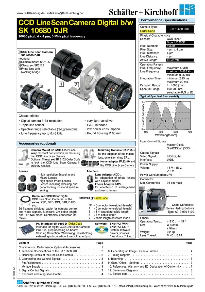
Schäfter+Kirchhoff SK512CSH User manual

Instruction Manual SK512CSH shared_Titel_ML.indd
SK512CSH
Monochrome Line Scan Camera
512 pixels 14 x 14 µm², line frequency up to 35.70 kHz
Instruction Manual
SK512CSH
3
2
4
1
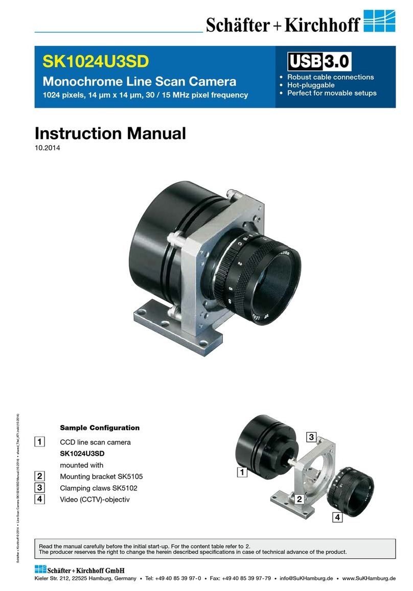
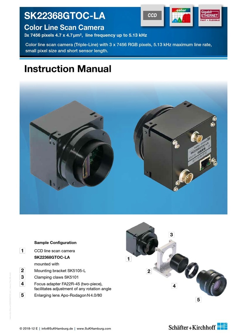
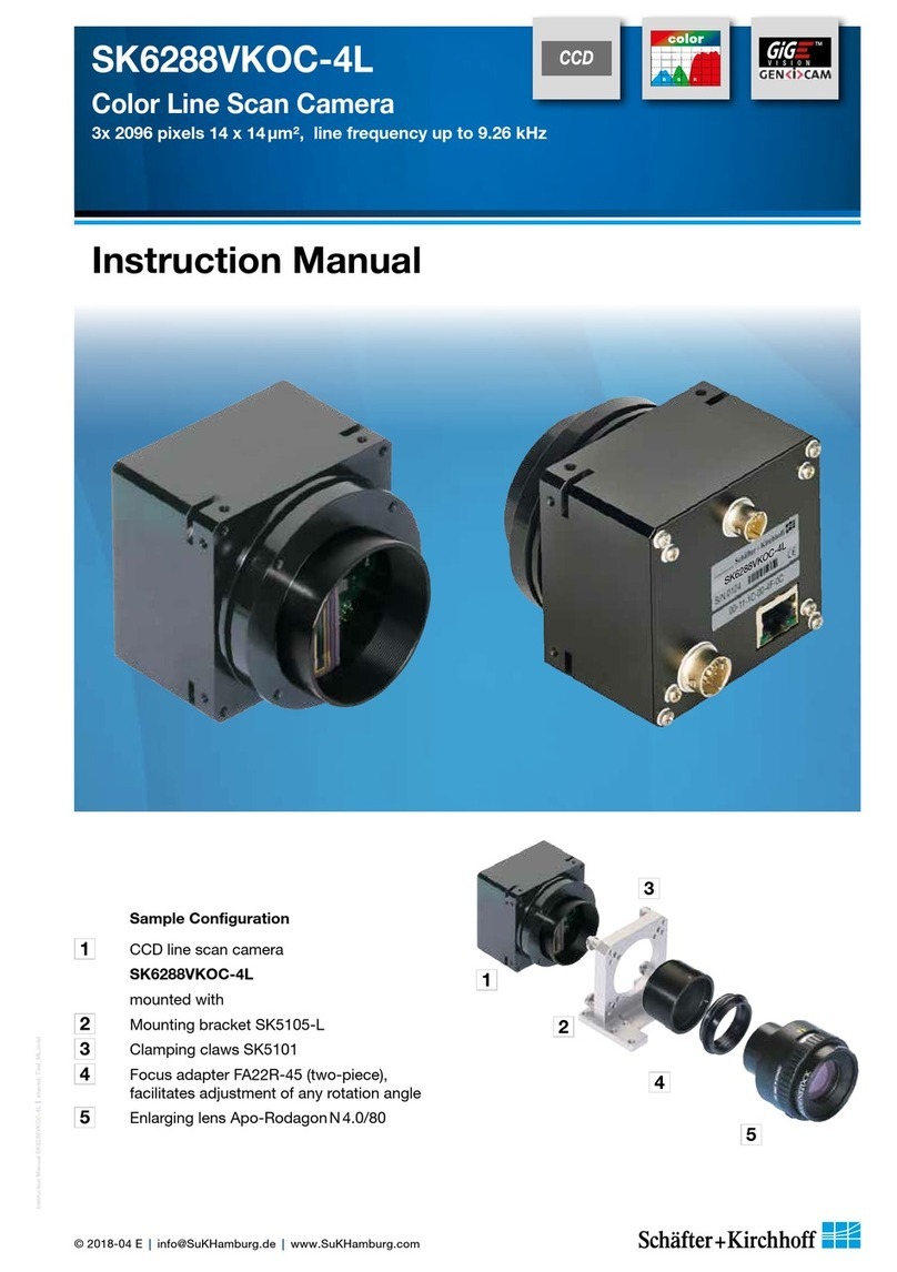
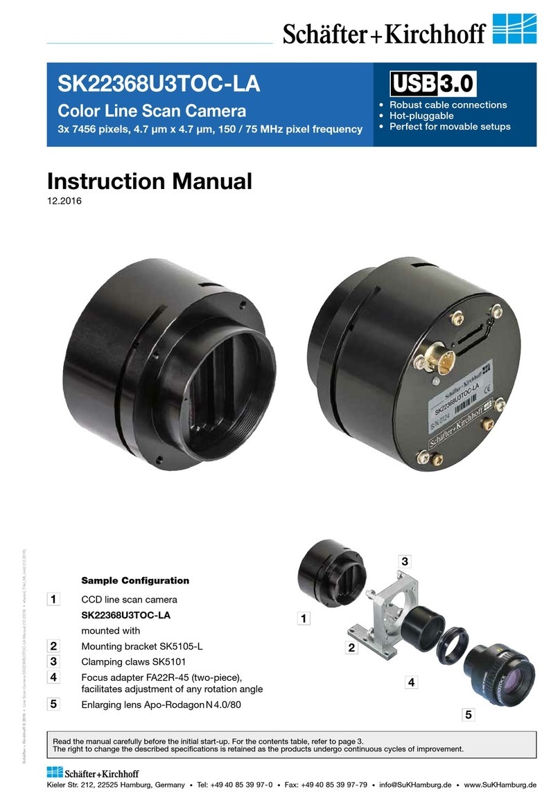
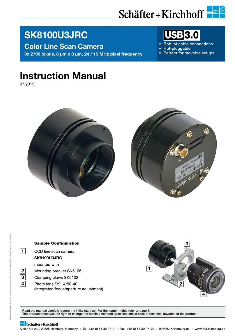
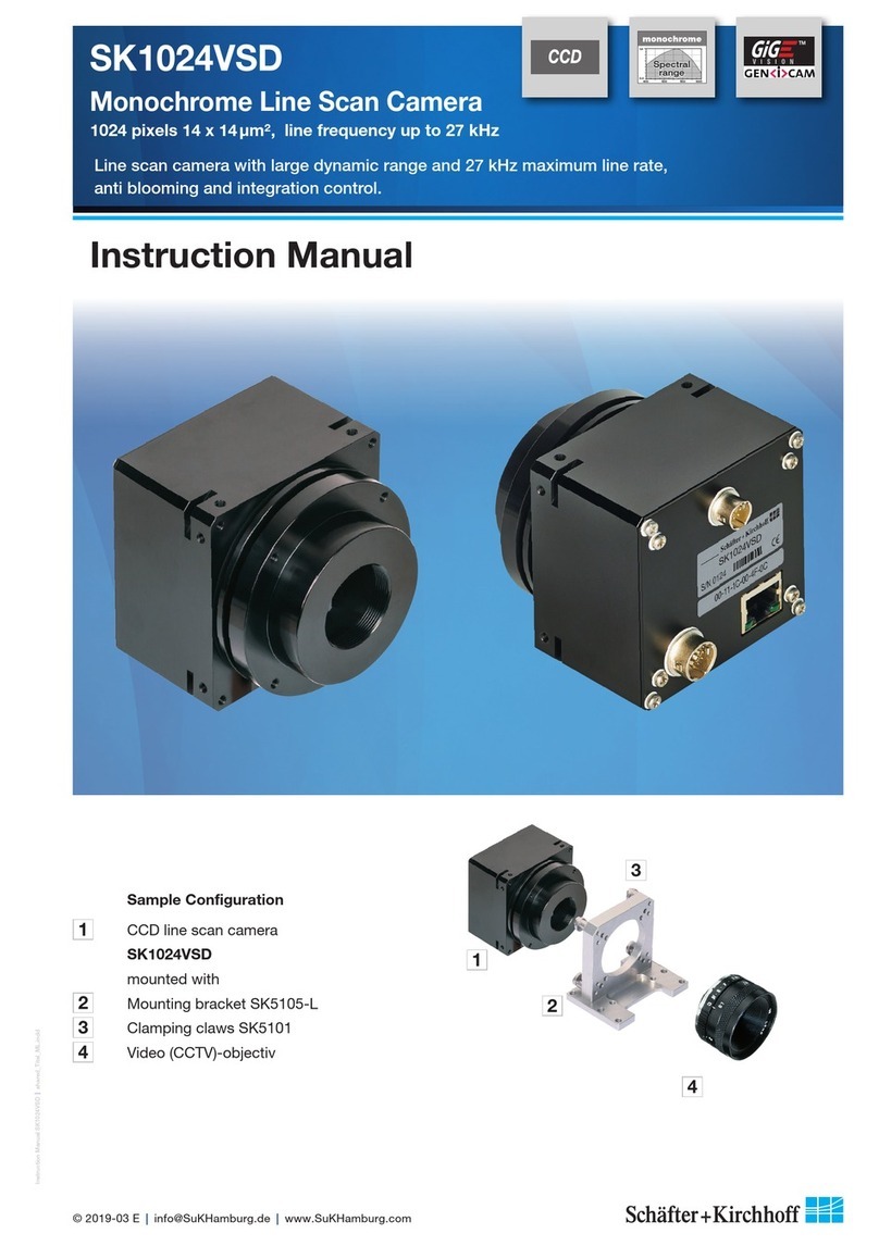
Sample Configuration
1CCD line scan camera
SK512CSH
mounted with
2Mounting bracket SK5105
3Clamping claws SK5102
4Video (CCTV)-objectiv
1.0
0.0
400 600
Wavelength (nm)
800 1000
Spectral
range

Instruction Manual SK512CSD shared_Contents.indd
2
Instruction Manual SK512CSD © 2020-11 E
Contents
Contents 2
How to Use this Instruction Manual 3
Safety Warnings 3
1 Introducing the SK512CSH Line Scan Camera ��������������������������������������������������� 4
1.1 Intended Purpose and Overview 4
1.2 Computer System Requirements 5
1.3 SK512CSH Line Scan Camera - Specifications 5
2 Installation and Setup ������������������������������������������������������������������������������� 6
2.1 Mechanical Installation: Dimensions, Mounting Options, and Heat Dissipation 6
2.2 Electrical Installation: Connections and I/O Signals 7
3 Interface and Camera Control ���������������������������������������������������������������������� 8
3.1 Input/Output Signals and Control System 8
3.2 Control Signals and Timing Diagram 11
4 Advanced Camera Control Functions ����������������������������������������������������������� 12
4.1 Camera Control by Commands 12
Set Commands 13
Request Commands 13
Synchronization of the Image Acquisition with the Feed Rate of the Object 14
4.2 Adjustments for Optimum Scan Results 15
Lens Focussing 15
Sensor Alignment 16
Gain/Offset Adjustment 16
5 Sensor Information �������������������������������������������������������������������������������� 18
Glossary 20
Warranty 21
Accessories 22

Instruction Manual SK512CSH shared_Hinweise.indd
3
Instruction Manual SK512CSH © 2020-11 E
How to Use this Instruction Manual
Electricity Warning
Assembly and initial operation of the line scan camera must be carried out under dry
conditions.
Do not operate the camera if you notice any condensation or moisture in order to avoid danger
of a short circuit or static discharge!
Risk of High Power Lighting
According to the application, laser or high power LED light sources might be used. These can
affect your eyesight temporarily or even cause permanent damage to the eyes or skin.
Do not look directly into the light beam!
Mechanics Warning
Ensure that the motion device and the scan way is free to move and that no obstacles are in
the way.
Do not place any part of the body in the way of moving parts!
Line scan cameras are mostly used in combination with a motion device such as a translation
stage, a conveyer or a rotational drive, as well as with high intensity light sources.
For assembly close down these devices whenever possible. Beyond that, please consider the
following warnings:
Safety Warnings
Please read the following sections of this Instruction Manual before unpacking, assembly or use
of the Line Camera System:
The safety warnings on this page
Introduction to the system, page 4
Installation and Setup, page 6
Keep this Instruction Manual in a safe place for future reference.
!

Introducing the SK512CSH Line Scan Camera
Instruction Manual SK512CSH shared_Introduction_CamLink.indd
4
Instruction Manual SK512CSH © 2020-11 E
1 Introducing the SK512CSH Line Scan Camera
PC
CameraLink
grabber for PC
12
3
1Line Scan Camera
2Power Supply
3Illumination
4Grabber with base
configuration
4
Normally, functions like Shading Correction, signal
modification with a look-up table (LUT) or the definition
of a region of interest (ROI) are implemented in
the grabber board. For special requirements these
functions can be made availabel within the camera,
please contact the Schäfter +Kirchhoff customer
support where appropriate.
The camera is supplied precalibrated, with factory
settings for gain and offset. A readjustment is normally
not necessary.
The successful use of the line scan camera requires
that the complete optical system is properly set up,
especially the location of the illumination, the degree
of focus of the lens and the aperture setting. The most
critical factor is the perpendicular alignment of the
sensor axis either with the object to be measured or the
direction of its relative travel when scanned. For further
guidance see section 4.2 Adjustments for Optimum
Scan Results (p. 15).
The SK line scan camera series is designed for a wide
range of vision and inspection applications in both
industrial and scientific environments. The SK512CSH
is compliant with CameraLink Specification Rev 1.1.
Data acquisition requires that the grabber board
conforms to the CameraLinkTM standard. The grabber
board provides the Start-Of-Scan (SOS) signals
and thereby determines the exposure time and line
frequency of the camera.
CameraLink reads the camera specifications from
configuration files. Prior to the iniatial start-up, the
appropriate camera specific file must be created for the
grabber in use.
Beyond, the configuration program SkCLConfig allows
the full parameterization of the camera settings, such
as gain, offset and pixel frequency, via the Camera-
LinkTM serial port interface. SkCLConfig uses the clser*.
dll driver that is supplied with the CameraLink grabber
board.
For the development of custom applications use the
software development kits released from the grabber
board producers.
1.1 Intended Purpose and Overview
Sensor category CCD Monochrome Sensor
Sensor type S12551-1024
Pixel number 512
Pixel size (width x height) 14 x 14 µm2
Pixel spacing 14 µm
Active sensor length 7.17 mm
Anti-blooming x
Integration control x
Shading correction x
Line synchronization modes Line Sync, Line Start, Exposure Start, Exposure Active
Pixel frequency 30 / 20 MHz
Maximum line frequency 35.70 kHz
Integration time 0.01 ... 20 ms
Dynamic range 1:2000 (rms)
Spectral range 200 ... 1000 nm
Video signal monochrome 8/12 Bit digital
Interface Camera Link
Voltage +5V, +15V
Power consumption 2.5 W
Casing Ø65 mm x 52.4 mm (Case type AC1)
Objective mount C-Mount
Flange focal length 17.53 mm
Weight 0.2 kg
Permissible casing temperature +5 ... +45°C
Introduction
5
Instruction Manual SK512CSH shared_SystemRequirements_Specs_ML.indd
Instruction Manual SK512CSH © 2020-11 E
1.2 Computer System Requirements
1.3 SK512CSH Line Scan Camera - Specifications
Introduction
The camera must be mounted thermally coupled
so that the acceptable casing temperature is not
exceeded during operation. Therefore applies to the
thermal resistance of the bracket or heat sink:
θamb - θcasing
RthHS ≤
Pcamera
where
RthHS [K/W] = thermal resistance of the bracket or heat
sink
θamb [°C] = ambient temperature
θcasing [°C] = temperature of the camera casing (not
to be confused with the internal camera
temperature that is queried and output
with the request command I32)
Pcamera [W] = camera power consumption
The SK512CSH is compliant with CameraLink
Specification Rev 1.1. It is operated in the "Base Confi-
guration" where the signals are carried over a single
connector/cable.
Power supply is provided by a separate power
connector.
Along with the camera the Schäfter +Kirchhoff confi-
guration program SkCLConfig is delivered. Provided
a clser**.dll driver by the grabber board manufacturer
is available, this program facilitates transferring the Set
and Request commands for camera configuration (see
page 4.1 Camera Control by Commands (p. 12)).

Installation and Setup
Instruction Manual SK512CSH shared_Installation-Mechanic_Axx-BGx_ML.indd
6
Instruction Manual SK512CSH © 2020-11 E
2 Installation and Setup
2.1 Mechanical Installation: Dimensions, Mounting Options, and Heat Dissipation
Casing type AC1
Mounting Options
When mounting the camera, pay attention to the
following:
• Mechanical stability to avoid vibrations.
• Good thermal coupling for cooling the housing.
The power consumption and the maximum
housing temperature of the camera are specified
in section 1.4 - Specifications.
The best fixing point of the camera is the collar for the
mounting bracket SK5105 (available as an accessory).
Four threaded holes M3x 6.5 mm provide further
options for customized brackets.
The length and weight of the optics might be beyond
the capability of the standard mounting bracket
SK5105. For this purpose, a second mounting bracket
type SK5105-2 to hold the tube extension ring(s) is
more appropriate.
Optics Handling
• If the camera and the optics are ordered as a kit,
the components are pre-assembled and shipped
as one unit. Keep the protective cap on the lens
until the mechanical installation is finished.
• If you must expose the sensor or lens surface,
ensure the environment is as dust-free as
possible.
• Gently blow off loose particles using clean
compressed air.
• The sensor and lens surfaces can be cleaned with
a soft tissue moistened with water or a water-
based glass cleaner.
Mounting bracket SK5105
Mounting system SK5105-2
for cameras with a tube
extension > 52 mm
Clamping set SK5102
Set of 4 pcs. clamping claws incl. hex
socket screws (EN ISO 4762–M3x12)
66
50
20
16.5
3.5
6.5
10 10
36
M3
Ø3.3
Ø4.3
6
15
50.3
41.7
70
63
40
Ø 42
M4
1/4’’ 20G
6
36
Ø 42
70
3.5 31.5
25
10
3.5
70
63
40
1/4’’20G
M4
Ø4.3

2
1
1Power +5 V, +15 V Hirose series 10A, male 6-pin
Total power: 2.5 W
Pin Signal Pin Signal
1+15 V 4+5 V
2+15 V 5GND
3+5 V 6GND
2
1
3
4
5
6
7
8
9
10
1112
2
1
3
4
5
6
Installation and Setup
7
Instruction Manual SK512CSH shared_Installation-Electric_CamLink_ML.indd
Instruction Manual SK512CSH © 2020-11 E
2.2 Electrical Installation: Connections and I/O Signals
Power Cable SK9015.xMF
Use this cable to feed external supply voltage into socket 1.
Connectors:
Hirose plug HR10A, female 6pin (camera side)
Lumberg SV60, male 6-pin connector (for supply voltage)
Length 1.5 m (standard) or 0.2 m
Power Supply Unit PS051515
Input: 100-240 VAC, 0.8 A, 50/60 Hz, IEC 320 C14 coupler
(for IEC C13 power cord)
Output: +5V DC, 2.5 A / +15 V DC, 0.5 A / -15 V DC, 0.3 A
Cable length 1 m, with Lumberg connector KV60,
female 6-pin
(for power cable SK9015.x or SK9016.x)
• For the SK512CSH line scan camera data transfer and camera control is provded by the Camera Link
interface 2. Use a control cable SK9018.... to connect the camera with the frame grabber card in the PC.
The maximum cable length is 10 m.
• The operating power has to be supplied by an external source into socket 1
• For any kind of synchronized operation the external trigger signal(s) have to be wired to the frame grabber
in addition. The camera can handle two trigger signals. These must be supplied on the CC1 and CC2-pins
of the Camera Link interface. For a detailed description of the interface see section 3 Interface and Camera
Control (p. 8).
Installation and Setup
Accessories (see also Accessories (p. 22)):
2Data Connector Miniature Delta Ribbon,
female 26-pin (MDR-26)
Signal Pin Pin Signal
GND 1 o o 14 GND
X0- 2 o o 15 X0+
X1- 3 o o 16 X1+
X2- 4 o o 17 X2+
Xclk- 5 o o 18 Xclk+
X3- 6 o o 19 X3+
SerTC+ 7 o o 20 SerTC-
SerTFG- 8 o o 21 SerTFG+
CC1 9 o o 22 CC1+
CC2+ 10 o o 23 CC2-
CC3- 11 o o 24 CC3+
CC4+ 12 o o 25 CC4-
GND 13 o o 26 GND
Control cable SK9018...
for line scan cameras with CameraLink interface
26-pin shielded cable, both ends with mini-ribbon
connector (male 26-pin)
SK9018.xMM
MM = connector both ends male
cable length 3 / 5 m or
length according to choice, max. 10m

The differential LVDS signals X0-X3 and XCLK are reserved for the transmission
of high-speed video data from the camera to the grabber board. The video data
is transmitted using numerous serial channels simultaneously, according to the
protocol for the channel link chipset from National Semiconductor.
The CameraLink standard defines the names of the pixel signals, the description of
the signal level and the pin assignments and pinout of the chip.
Signal Name I/O Type Description
D[0–11] O RS644 Pixel data, 00 = LSB, 11 = MSB
STROBE O RS644 Output data clock
Data are valid for a rising edge
LVAL O RS644 Line Valid, active High Signal
I = Input, O = Output, IO = Bidirectional, P = Power/Ground, NC = not connected
Warning: FVAL and DVAL are not used here as defined in the CameraLink standard.
FVAL is always set to the value = 1 (low).
DVAL is always set to the value = 1 (high).
Bit DS90CR285
Pin Name Bit DS90CR285
Pin Name
D 0 Tx0 D 8 Tx7 NC Tx15 STROBE TxCLK
D 1 Tx1 D 9 Tx8 NC Tx16 LVAL Tx24
D 2 Tx2 D10 Tx9 NC Tx17
D 3 Tx3 D11 Tx12 NC Tx18
D 4 Tx4 NC Tx10 NC Tx19
D 5 Tx6 NC Tx11 NC Tx20
D 6 Tx27 NC Tx13 NC Tx21
D 7 Tx5 NC Tx14 NC Tx22
Bit allocation 12-bit data: D[0-11], Serial command: F12
Bit DS90CR285
Pin Name Bit DS90CR285
Pin Name
D 0 Tx0 NC Tx7 NC Tx15 STROBE TxCLK
D 1 Tx1 NC Tx8 NC Tx16 LVA L Tx24
D 2 Tx2 NC Tx9 NC Tx17
D 3 Tx3 NC Tx12 NC Tx18
D 4 Tx4 NC Tx10 NC Tx19
D 5 Tx6 NC Tx11 NC Tx20
D 6 Tx27 NC Tx13 NC Tx21
D 7 Tx5 NC Tx14 NC Tx22
Bit allocation 8-bit data: D[0-7], Serial command: F8
The bit allocation conforms to the CameraLink Standard basic configuration.
Video data
Interface and Camera Control
Instruction Manual SK512CSH shared_Interface_CamLink_ML.indd
8
Instruction Manual SK512CSH © 2020-11 E
3 Interface and Camera Control
Signal Name I/O Type Description
LINE SYNC A I RS644 CC1 - Synchronization input (SOS)
LINE SYNC B I RS644 CC2 - Start Integration period in dual synchro modus
(only cameras with Integration Control)
FRAME SYNC I RS644 CC3 - Start acquisition of 2D area scan
I RS644 CC4 - not used
I = Input, O = Output, IO = Bidirectional, P = Power/Ground, NC = not connected
Camera control
3.1 Input/Output Signals and Control System

Interface and Camera Control
Instruction Manual SK512CSH shared_Interface_CamLink_ML.indd
9
Instruction Manual SK512CSH © 2020-11 E
Signal Name I/O Type Description
SerTFG O RS644 Differential pair for serial communications to
the grabber board
SerTC I RS644 Differential pair for serial communications from
the grabber board
The CameraLink interface supports two LVDS signal pairs for communication
between the camera and grabber board, which conform with the RS232 protocol
for asynchronous communication:
– full duplex, no handshake
– 9600 baud, 8-bit, no parity bit, 1 stop bit.
Serial communication
Block Diagram of Camera Link Base Configuration

Interface and Camera Control
Instruction Manual SK512CSH shared_Interface_CamLink_ML.indd
10
Instruction Manual SK512CSH © 2020-11 E
Clock
Select
AD
Conver-
ter
Exposure
Time
Advanced
Sync Control
SyC 2
SynC A
SynC B
SyC 0,1
Output
Format
Select
CCD
Sync
Select
Pixel
Counter
Shading
Correc-
tion
Look Up
Table
(LUT)
CC1
SOS in
CCLK
to
Camera Link
Interface
pixel clock Oscillator
pixel
adress
DVAL
M0 M1
M3 M4
M4
video
video D[0-11] (monochrome cameras)
R[0-7], G[0-7], B[0-7] (RGB cameras)
trigger
Restart
SOS
discharge
CC2
LVAL
Port A, B, C
Camera Link
Base
SynC 3...7
Sync
Divider
M3
Region
of Inte-
rest (ROI)
pixel clock
~
~
~
Logical Diagram of the Camera Control System

Interface and Camera Control
11
Instruction Manual SK512CSH SK512CSH_CameraControl(3d)_CamLink_CtrlSignals-Timing.indd
Instruction Manual SK512CSH © 2020-11 E
The control signals needed to run the CCD line scan
camera are "Clock" (CCLK) and "Start Of Scan" (SOS).
The clock signal is generated internally by a program-
mable oscillator.
The SOS can be initiated internally by adjusting the
Exposure Time or externally by the grabber board.
For internal control, the camera must be set in the
'Free Run' mode by using command 'M0'. When the
SOS signal is generated by the grabber board then
the camera must be set to the 'external Trigger CC1'
mode using 'M3'.
The frequency of the 'SOS' signal determines the
number of lines that are read per second (= line
frequency). On each rising edge of this signal, the
accumulated charges within the sensor are transferred
to the analog transport registers in parallel with the
sensor line information.
Thus, the frequency of the clock signal determines the
speed at which the charges of the individual pixels of
the line sensor appear in the camera video output. At
each positive edge, the accumulated charges of the
subsequent pixels are released as video output.
The SK512CSH camera requires 816 clock pulses for a
line scan to be read out completely. This corresponds
to the number of pixels per line plus several extra
cycles prior and past the charge acquisition.
Accordingly, the line frequency is limited to 1/816 part
of the clock freqeuncy. Lower line frequency values can
be used without restriction. The minimum SOS pulse
length is 30 ns.
Interface and Camera Control
3.2 Control Signals and Timing Diagram
≥30 ns
1 3 512511510iioo o o o
i2
1 3 5125115102
o
ioo o o oi o
SOS
CC1
Input 43 Clock Cycles 512 Clock Cycles 261 Clock Cycles
i = isolation pixels, o = overclocking
1 3 512511510iioo o o o
i2
1 3 5125115102
o
ioo o o oi o
CCLK
STROBE
LVAL
D[0-11]
Video
intern
15 ns
Output

Advanced Camera Control Functions
Instruction Manual SK512CSH SK512CSH_CameraControl(4)_ByCommands.indd
12
Instruction Manual SK512CSH © 2020-11 E
4 Advanced Camera Control Functions
4.1 Camera Control by Commands
The configuration program SkClConfig provides the option to adjust camera settings, such as gain, offset, trigger
modes, by sending control commands directly.
Similarly, current parameters, as well as specific product information, can be read from the camera using the
request commands. All set and request commands are listed in the tables below.
• The commands are entered in the 'Input' field in the 'Camera Control' section of the "Camera Gain/Offset
Control" dialog. 1
• In the 'Output' field, either the acknowledgement of the set commands (0 = OK, 1 = not OK) or the return
values of the request commands are output. 2
The parameter settings are stored in the non-volatile flash memory of the camera and are available after a rapid
start-up, even after a complete shut down or loss of power.
1 2
Gain/Offset Control dialog: Camera Control input and output in the bottom left section

Advanced Camera Control Functions
Instruction Manual SK512CSH SK512CSH_CameraControl(4)_ByCommands.indd
13
Instruction Manual SK512CSH © 2020-11 E
Set Commands
Set Operation Description
Goooo<CR> gain setting 0-24 dB
Oppp<CR> offset setting
F8<CR> output format: 8 bit output data
F10<CR> output format: 10 bit output data
F12<CR> output format: 12 bit output data
C30<CR> camera clock: 30 MHz data rate
C20<CR> camera clock: 20 MHz data rate
T0<CR> test pattern off / SCM off
T1<CR> test pattern on (turns off with power off)
T2<CR> shading correction on
T3<CR>
auto program Shading Correction / SCM on
T4<CR> copy flash memory 1 to SCM
T5<CR> save SCM to flash memory 1
T6<CR> video out = SCM data
T7<CR> copy Flash Memory 2 to LUT Memory
T8<CR> save LUT Memory to Flash Memory 2
T9<CR> output data = LUT data
M0<CR> free run (no triggering) at selected line
rate
M1<CR> line trigger mode1: extern trigger next
Line CC1-input
M2<CR> free run (no triggering) at maximum line
rate
M3<CR> extern SOS CC1-input and integration
control CC1 or CC2-input
M4<CR> line trigger mode4: external triggering and
restart
Mx+8 frame trigger external, start on falling
edge, CC3 input
Mx+16 frame trigger external, active low, CC3
input
Axxxx<CR> SCM address (Axxxx = A0-A511) or
LUTM (Axxxx = A32768-A36863)
Dxxxx<CR> Memory data (xxxx = 0-4095), increment
memory address counter
Eyyyyy<CR> frames / multiframe (yyyyy = 0-32767)
EFyyyyy<CR> external frame trigger delay
(yyyyy = 0-32767 lines)
Nyyyyy<CR> lines / frame (yyyyy = 1-32767)
Vyyyyy<CR> extern sync divider (yyyyy = 1-32767)
Ypppp<CR> set sync control (ppp = 0-4095)
Wyyyyy<CR> line clock frequency
(yyyyy = 50-35700) [Hz]
WLyyyyy<CR> Window Pixel length (yyyyy =1-Line length)
WFyyyyy<CR> Window First Pixel (yyyyy = 1-Line length)
Xyyyyy<CR> exposure time (yyyyy = 10-20000) [µs]
SDXT<CR> enable DXT (decoupling of line clock
frequency and exposure time)
RDXT<CR> disable DXT (decoupling of line clock
frequency and exposure time)
SLUT<CR> enable LUT
RLUT<CR> disable LUT
SNES<CR> enable NES (no EEPROM save)
RNES<CR> disable NES (no EEPROM save)
RESET<CR> reset Memory to manufacturer default
Request Commands
Request Return Description
K<CR>
SK512CSH
returns SKtype number
R<CR> Rev. 2.50 returns Revision number
S<CR> SNr00163 returns Serial number
I<CR>
SK512CSH
Rev. 2.50
SNr00163
camera identification readout
I1<CR> VCC: yyyyy returns VCC (1=10mV)
I2<CR> VDD: yyyyy returns VDD (1=10mV)
I3<CR> moo: yyyyy returns mode of operation
I4<CR> CLo: yyyyy returns camera clock low
frequency (MHz)
I5<CR> CHi: yyyyy returns camera clock high
frequency (MHz)
I6<CR> Ga: yyyyy returns gain
I8<CR> Of: yyyyy returns offset
I19<CR> Tab: yyyyy returns number of video
channels
I20<CR> CLK: yyyyy returns selected clock
frequency (MHz)
I21<CR> ODF: yyyyy returns selected output data
format
I22<CR> TRM: yyyyy returns selected trigger mode
I23<CR> SCO: yyyyy returns shading corr. on/off
I24<CR> Exp: yyyyy returns exposure time
I25<CR> miX: yyyyy returns min. exposure time (µs)
I26<CR> LCK: yyyyy returns line frequency (Hz)
I27<CR> maZ: yyyyy returns max. line frequency (Hz)
I28<CR> TSc: yyyyy returns Sync Divider
I29<CR> SyC: yyyyy returns Sync Control
I30<CR> Lin: yyyyy returns Lines/Frame
I31<CR> DXT: yyyyy returns DXT on/off
I32<CR> Tmp: yyyyy returns Video Board Temper.
I33<CR> FSD: yyyyy returns Frame Trigger Delay
I36<CR> WPL: yyyyy returns Window Pixel Length
I37<CR> WFP: yyyyy returns Window First Pixel
I38<CR> LUT: yyyyy returns LUT on/off
I39<CR> KST: yyyyy returns Status
Range of values:
oooo = 0 ... 1023
ppp = 0 ... 255
xxxx = 4 digits integer value as ASCII
yyyyy = 5 digits integer value as ASCII
LUT: Lookup Table
SCM: Shading Correction Memory
SOS: Start of Scan
Acknowledgement for all set commands:
0 = OK, 1 = not OK

FOV
S
V0
Pixel #1
Pixel #1
WP/ ß
CCD Sensor
Scan Object
Synchronization
Instruction Manual SK512CSH shared_CameraControl(3)_Sync_ML.indd
14
Instruction Manual SK512CSH © 2020-11 E
Synchronization
Synchronization of the Image Acquisition with the Feed Rate of the Object
A line scan camera produces a two-dimensional image by moving either the object or the camera. The direction of
the translation movement must be orthogonal to the sensor axis of the line scan camera.
In order to obtain an image with the correct aspect ratio, a line synchronous feed is required. With RGB color
sensors, the color sequence of the individual sensor lines must also be taken into account when processing
the sensor data. The software development kits from Schäfter+Kirchhoff contain easy-to-use functions for this
purpose.
If the object speed is variable or the accuracy requirements are high, external synchronization is required. The
various synchronization modes are described in the next section.
The optimal scan speed for a given line frequency is
calculated as follows:
WP·fL
VO=
ß
If the scanning speed is fixed, the line frequency must
be adjusted accordingly in order to obtain the correct
aspect ratio in the image:
VO·ß
fL=
WP
VO= object scan velocity
WP= pixel width
fL= line frequency
S= sensor length
FOV = field of view
ß= magnification factor
= S / FOV
Example 1:
Calculating the scan velocity for a given field of view and a given line frequency:
Pixel width = 14 µm
Line frequency = 35.70 kHz
S= 7.17 mm
FOV = 20 mm
14 µm · 35.70 kHz
VO=
(7.17 mm / 20 mm)
= 1394 mm/s
Example 2:
Calculating the line frequency for a given field of view and object scan velocity:
Pixel width = 14 µm
Scan velocity = 1300 mm/s
S= 7.17 mm
FOV = 20 mm
1300 mm/s · (7.17 mm / 20 mm)
fL=
14 µm
= 33.3 kHz

Camera Control and Performing a Scan
15
Instruction Manual SK512CSH shared_CameraControl(2)_Adjustments-1_ML.indd
Instruction Manual SK512CSH © 2020-11 E
Camera Control and Performing a Scan
4.2 Adjustments for Optimum Scan Results
•Lens focussing
•Sensor alignment
•Gain/Offset
•Shading correction
•Integration time
•Synchronization of the sensor exposure
and the object surface velocity, trigger
mode options.
Prior to a scan, the following adjustments and parameter settings should be considered for optimum
scan signals:
Start with the signal window / oscilloscope display. Any changes in the optical system or camera
parameters are displayed in real-time when using an open dialog box.
Lens Focussing
The real time Signal Window facilitates the effective focussing of the line scan camera system, even for
two-dimensional measurement tasks. For determining the correct focus, the edge steepness at dark-bright transi-
tions and the modulation of the line scan signal are the most important factors.
Adjust the focus with the aperture fully open to limit the depth of field and enhance the effects of changing the
working distance.
If the sensor is overloaded when the aperture is fully open, the easiest way to reduce the signal amplitude is to
shorten the integration time, as described in section Optimum brightness adjustment, Integration Time (p.
16).
Out-of-focus:
• Low edge steepness
• Signal peaks are blurred
• High spatial frequencies with low modulation depth
Optimum focus:
• Dark-bright transitions with steep edges
• Large modulation in the signal peaks
• High spatial frequencies with high modulation depth
steep edges
high modulation
depth
low modulation depth
low edge steepness

Camera Control and Performing a Scan
Instruction Manual SK512CSH shared_CameraControl(2)_Adjustments-1_ML.indd
16
Instruction Manual SK512CSH © 2020-11 E
Sensor Alignment
If you are using a linear light source, check the alignment of the light source and sensor before shading correction,
as rotating the line sensor will result in asymmetric vignetting.
Sensor and line lighting slightly twisted in
relation to each other, asymmetric vignetting
Sensor and line lighting aligned in parallel,
symmetric vignetting
Gain/Offset Adjustment
The cameras are supplied with factory-set gain/offset. Open the "Gain/Offset Control" dialog to adjust these
settings.
Platzhalter für Grafik und Text in anderen Ebenen
Adjustment principle
1. Offset
To adjust the zero baseline of the video signal, totally
block the incident light and enter "00" (volts) for
channel 1.
For a two- or multi-channel sensor, minimize any diffe-
rences between the channels by adjusting the other
Offset sliders.
A slight signal noise should be visible in the zero
baseline.
2. Gain
Illuminate the sensor with a slight overexposure in order
to identify the amplitude clipping. Use the Gain slider
"1" to adjust the maximum output voltage.
For a two- or multi-channel sensor, minimize any diffe-
rences between the channels by adjusting the other
Gain sliders.
For the full 8-bit resolution of the camera, the maximum
output voltage is set to 255 and for 12-bit is set to
4095.
Offset
and gain
adjustment
for more than
one gain/
offset channel
2. Adjust the gain of channel1.
Minimize the difference
between the channels with
the other gain controls.
1. Adjust the zero level of
channel 1. Minimize the
difference between the
channels using the other
Offset controls.
The gain/offset dialog contains up to 6 sliders for altering gain and offset. The number of active sliders depends
on the individual number of adjustable gain/offset channels of the camera.
Enter commands for advanced software functions in the 'Camera Control' field (see page 12).
Gain/Offset
Control dialog

Instruction Manual SK512CSH shared_blank.indd
17
Instruction Manual SK512CSH © 2020-11 E

Sensor Information
Instruction Manual SK512CSH shared_Sensor_S12551-1024.indd
18
Instruction Manual SK512CSH © 2020-11 E
5 Sensor Information
Manufacturer: Hamamatsu
Type: S12551-1024
Data source: Hamamatsu CCD linear image sensors S12551 series
Cat. No. KMPD1147E05 Mar. 2020 DN
a) Features
• 1024 pixels, pixel size: 14 x 14 µm
• High CCD node sensitivity: 13 µV/e-typ.
• Readout speed: 40 MHz max.
• Anti-blooming function
• Built-in electronic shutter
b) Device Structure (conceptual drawing)

Sensor Information
Instruction Manual SK512CSH shared_Sensor_S12551-1024.indd
19
Instruction Manual SK512CSH © 2020-11 E
c) Spectral Response (without window, typical example)
Spectral response with quartz glass is decreased according to the spectral transmittance characteristics of
window material.
d) Spectral Transmittance Characteristics of Window Material
e) Electrical and Optical Characteristics (Ta = 25°C)

Instruction Manual SK512CSH shared_Glossary_Kurzfassung-1Seite.indd
20
Instruction Manual SK512CSH © 2020-11 E
Glossary
Blooming
Extended illumination of saturated pixels, which are not
able to accumulate further charge due to long exposure,
leads to charge overflow into adjacent pixels. This effect
is called blooming. Blooming causes a corruption of
the geometrical allocation of image and object in the
line signal. CCD line scan cameras with anti-blooming
sensors direct the abundant charge to a ”drain gate”.
Charge overflow into adjacent, less illuminated pixels is
prevented. Depending on pixel frequency and spectral
range, overexposure up to factor of 50 can thus be
handled.
Exposure period
is the illumination cycle of a line scan sensor. It is the
integration time plus the additional time to complete
the read-out of the accumulated charges and the output
procedure. While the charges from a finished line scan
are being read out, the next line scan is being exposed.
The exposure period is a function of the pixel number and
the pixel frequency. The minimum exposure period of
a particular line scan camera determines the maximum
line frequency that is declared in the specifications.
Integration control
Cameras with integration control are capable of
curtailing the integration time within an exposure
period. This performs an action equivalent to a shutter
mechanism.
Integration time
The light-sensitive elements of the photoelectric sensor
accumulate the charge that is generated by the incident
light. The duration of this charge accumulation is called
the integration time. Longer integration times increase
the intensity of the line scan signal, assuming constant
illumination conditions. The complete read-out of
accumulated charges and output procedure determines
the minimum exposure period.
Line frequency, line scan frequency
is the reciprocal value of the exposure period. The
maximum line frequency is a key criterion for line scan
sensors as this is the limiting factor for the scan velocity.
Optical resolution
Two elements of a line scan camera determine the optical
resolution of the system: first, the pixel configuration of
the line sensor and, secondly, the optical resolution of
the lens. The worst value is the determining value. In a
phased set-up, both are within the same range.
The optical resolution of the line sensor is primarily
determined by the number of pixels and secondarily by
their size and spacing, the inter-pixel distance. Currently
available line scan cameras have up to 12 000 pixels,
ranging from 4 to 14 µm in size and spacing, for sensors
up to 56 mm in length and line scan frequencies up to
83 kHz.
During a scanning run, the effective resolution perpen-
dicular to the sensor orientation is determined by the
velocity of the scan and by the line frequency
Pixel frequency
The pixel frequency for an individual sensor is the rate
of charge transfer from pixel to pixel and its ultimate
conversion into a signal.
Region of Interest
A freely programmable window (region of interest, ROI)
can be applied to the line sensor so that only the pixel
information within the ROI can reach the memory.
By only illuminating these ranges, data volume and data
processing is accelerated for both line and area scan
acquisitions.
Constraint: the ROI memory allocation must be divisible
by 8.
Shading correction
Shading Correction, section 3.2
SoI (Start of Integration)
In addition to SoS, cameras with Integration
Control function generate an internal SoI-signal that
initiates the integration period.
SoS (Start of Scan)
is an internally generated trigger signal for sequential
control of the camera, The signal is induced either by an
internal counter or by an external line synchronization
signal, depending on the selected line synchronization
mode.
Synchronization
Advanced Synchronization Control, section 4.2
Synchronization
To obtain a proportional image with the correct aspect
ratio, a line synchronous transport with the laterally
correct pixel assignment is required. The Line
frequency and constant object velocity have to be
compatible with each other.
For more accurate requirements or with a variable object
velocity, external synchronization is necessary.
Synchronization of the Imaging Procedure and the
Object Scan Velocity, section 3.2
Table of contents
Other Schäfter+Kirchhoff Security Camera manuals

Schäfter+Kirchhoff
Schäfter+Kirchhoff SK22368U3TOC User manual

Schäfter+Kirchhoff
Schäfter+Kirchhoff SK12240U3KOC-LB User manual

Schäfter+Kirchhoff
Schäfter+Kirchhoff SK1024U3SD User manual

Schäfter+Kirchhoff
Schäfter+Kirchhoff SK1024VSD User manual

Schäfter+Kirchhoff
Schäfter+Kirchhoff SK22368U3TOC-LA User manual

Schäfter+Kirchhoff
Schäfter+Kirchhoff SK 10680 DJR User manual

Schäfter+Kirchhoff
Schäfter+Kirchhoff SK6288VKOC-4L User manual

Schäfter+Kirchhoff
Schäfter+Kirchhoff SK22368GTOC-LA User manual

Schäfter+Kirchhoff
Schäfter+Kirchhoff SK1024U3HU User manual

Schäfter+Kirchhoff
Schäfter+Kirchhoff SK8100U3JRC User manual