CAME PXWDTVE User manual

PXWDTVE
FA00489M4A

B
8
80 °
0 6 12 [m]
[m]
8
2
4
3
1
A
AA
A
B
D
E
F
C
C
A
A
C
DL1
DL4DL5
DL3
DL2
DIP-SWITCH
RV1
RV2
JP1
JP2
GND
+6 V
2 - FA00489M4A-ver.1-03/2017

CE
DF
2
1
+ –
3 - FA00489M4A-ver.1-03/2017

I
J
H
2
1
G
4 - FA00489M4A-ver.1-03/2017

KM
LN
1
2
1
2
1
2
5 - FA00489M4A-ver.1-03/2017

P
Q
R
2
12
O
1
2
1
6 - FA00489M4A-ver.1-03/2017

S
12
1
2
UT
7 - FA00489M4A-ver.1-03/2017

8 - FA00489M4A-ver.1-03/2017
Avvertenze generali
Importanti istruzioni per la sicurezza delle persone: LEG-
GERE ATTENTAMENTE! • L’installazione, la programmazio-
ne, la messa in servizio e la manutenzione devono essere
eettuate da personale qualificato ed esperto e nel pieno
rispetto delle normative vigenti. • Indossare indumenti e
calzature antistatiche nel caso di intervento sulla scheda
elettronica.
• Conservare queste avvertenze. • Il prodotto deve essere
destinato solo all’uso per il quale è stato espressamente
studiato.
Pericolo di esplosione se la batteria è sostituita con altra
di tipo errato. • Le batterie, una volta esaurito il loro ciclo di
vita, non devono essere gettate con i rifiuti indierenziati,
ma raccolte separatamente ed avviate a corretto recupero.
• Tenere le batterie lontane dalla portata dei bambini. • Se
ingerite contattare immediatamente un medico.
Descrizione
Sensore a doppia tecnologia (infrarosso passivo e microonda)
radio da esterno. L’allarme viene generato solo quando en-
trambe le tecnologie rilevano in modo concorde.
Il sensore è protetto dal rischio di rimozione, grazie ad un si-
stema integrato anti-strappo.
Descrizione delle parti B
1 LED di segnalazione
B Dip-switch
C Jumpers
D Potenziometro per la re-
golazione infrarosso
E Potenziometro per la re-
golazione micro-onda
F Tamper anti-strappo
Legenda LED
LED Colore Significato
DL1 Rosso Rilevazione IR
DL2 Rosso Rilevazione microonda
DL3 Blu Allarme
DL4 Rosso Apprendimento
DL5 Verde Apprendimento
Descrizione Jumpers
JP1 Abilitazione/Disabilitazione Tamper
APERTO Abilitato CHIUSO Disabilitato
JP2 Abilitazione/Disabilitazione Tamper anti-strappo
APERTO Abilitato CHIUSO Disabilitato
JP3 Abilitazione/Disabilitazione DL3 LED di allarme
APERTO Disabilitato CHIUSO Abilitato
Descrizione Dip-switch
DEFAULT
DIP1 (Supervisione)
ON Abilitata OFF Disabilitata
DIP2 (Test radio)
ON Abilitato (trasmette
ogni secondo) OFF
Disabilitato. Funziona-
mento normale
DIP3 (Modalità di funzionamento)
ON Test OFF Normale
Spostare il DIP3 esclusivamente in assenza di rilevazione (se
i LED sono abilitati, spostare il DIP quando sono tutti spenti).
Il sensore conferma il passaggio al modo test oppure normale
emettendo dei suoni:
- TEST -> NORMALE: alcuni "beep" veloci
- NORMALE -> TEST: "beep" lungo
Se non si sente alcun suono significa che il sensore NON è
passato al modo scelto: in questo caso ripetere lo spostamen-
to del DIP3.
DIP4 (Regolazione LED e BUZZER)
ON DL1, DL2 e BUZZER
abilitati. OFF
DL1, DL2 e BUZZER
disabilitati. DL3 è ge-
stito da JP3. Utilizzare
questa modalità in
funzionamento nor-
male per aumentare
la durata delle bat-
terie.
DIP5-DIP6 (Walk test)
OFF
Funzionamento
normale
ON Funzionamento
Walk Test IR (DL1
acceso fisso)
OFF
ON Funzionamento Walk Test MW (DL2 acceso fisso)
OFF
I walk test permettono la regolazione dell’area di rilevazione
del sensore. Le regolazioni di infrarosso e microonda sono
indipendenti.
DIP7 (Range IR)
ON
Portata massima cir-
ca 18 m. Regolazione
della portata massima
(tramite RV1) = circa 9
÷ 18 m
OFF
Portata massima cir-
ca 12 m. Regolazione
della portata massi-
ma (tramite RV1) =
circa 3 ÷ 12 m
Ad ogni spostamento del DIP7 attendere 10÷20 s.
Dati tecnici
Tipo PXWDTVE
Alimentazione n° 2 batteria al Litio a
3 V (CR123A)
Frequenza (MHz) 433.92/868.65
Assorbimento in standby (uA) 40
Assorbimento in allarme (mA) < 80
Potenza segnale radio (dBm) < 10
Frequenza microonda (GHz) 24
Portata max a 25 °C (m)* 12
Portata minima a 25 °C (m)* 3
ITALIANO

9 - FA00489M4A-ver.1-03/2017
Tipo PXWDTVE
Autonomia stimata (anni) ** 2
Temperatura d’esercizio (°C) -40 / +50
Dimensioni (mm) 190x85x75
Grado di protezione (IP) 54
Resistenza all'impatto (IK) 10
EN50131-1,EN50131-2-4 Grado 2,EN50131-5-3,EN50131-
6: Tipo C, EN50130-5, Ambientale Classe III
* È l'intervallo di tempo entro il quale le due testine IR devono
attivare la microonda e rilevare l'allarme.
** La durata stimata delle batterie del sensore è inversamente
proporzionale al numero di rilevazioni a cui è sottoposto (indi-
pendentemente dal fatto che il sistema di allarme sia o meno
inserito). Se il sensore è installato in zone ad alta frequenza di
passaggio l'autonomia della batteria si riduce.
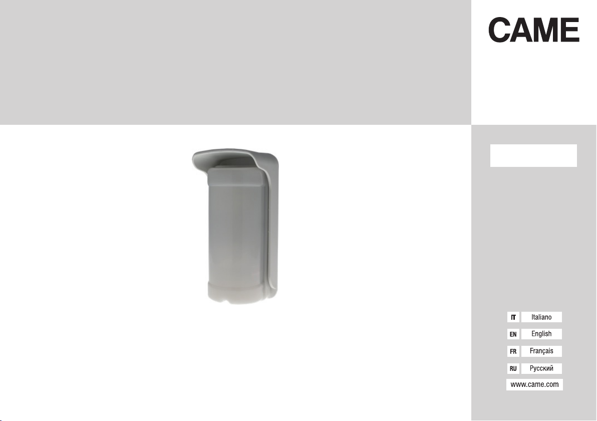
Potenziometri
DRV1: regolazione della portata di rilevazione della testina
superiore (infrarosso). Ruotare in senso orario per aumentarne
la portata.
ERV2: regolazione della portata di rilevazione della testina
inferiore (microonda). Ruotare in senso orario per aumentarne
la portata.
NOTA. Prima di alimentare il sensore accertarsi che RV1
e RV2 siano regolati per la massima portata (ruotati com-
pletamente in senso orario). In caso contrario il sensore
potrebbe ricevere un segnale troppo debole oppure non
riceverlo aatto: i LED non si accenderanno.
Accensione
Ruotare i potenziometri in senso orario. Impostare i DIP1,
DIP2, DIP5, DIP6 in OFF; DIP3, DIP4 in ON e il DIP7 a scelta.
Aprire il jumper JP1 e chiudere il jumper JP2 e JP3 e alimen-
tare il sensore.
Le impostazioni possono essere modificate di seguito senza
togliere l'alimentazione. Il sensore è pronto per l'inizializzazio-
ne che durerà 2 minuti.
Inizializzazione
Alimentare il sensore. I LED DL1 e DL2 si accendono per
alcuni secondi e poi si spengono: alcuni ‘beep’ confermano
l’avvenuta inizializzazione.
Per re-inizializzare il sensore togliere l’alimentazione, preme-
re il tamper (JP1 = APERTO) e rialimentare il sensore.
È possibile interrompere l’inizializzazione in qualsiasi momento
tenendo premuto il tamper (JP1 = APERTO) per alcuni secondi
fino allo spegnimento dei LED. Rilasciare il tasto tamper.
Modo TEST o NORMALE
Modo TEST (DIP3 = ON)
Questa modalità trasmette l’allarme ad ogni rilevazione di
movimento. Il sensore esce automaticamente dal modo TEST
dopo circa 5 min, anche senza posizionare il DIP3 in OFF. L’ac-
censione dei LED e un ‘beep’ confermano il passaggio dalla
modalità TEST a NORMALE.
Modo NORMALE (DIP3 = OFF)
In questa modalità, dopo una rilevazione e l’invio di un allar-
me, il sensore attende un “tempo di quiete” (120 s non modi-
ficabile) prima di considerare un nuovo allarme.
Se durante il tempo di quiete NON avviene alcuna rilevazione
il sensore torna ad essere attivo e pronto per un’altra rileva-
zione.
Il modo NORMALE consente un consumo minore e una mag-
giore durata delle batterie. Posizionare il DIP3 in ON: un ‘beep’
lungo conferma il passaggio dalla modalità NORMALE a TEST.
Apprendimento
Alimentare il sensore e attendere il termine della fase di ini-
zializzazione. È indierente che il sensore sia in modo TEST
oppure in modo NORMALE (DIP3).
Aprire il jumper JP1 e assicurarsi che la centrale sia in moda-
lità apprendimento.
Premere e rilasciare per 3 volte il pulsante a levetta del tam-
per in un tempo massimo di 5 secondi. Durante la fase di
apprendimento DL4 (rosso) e DL5 (verde) presenti sull'espan-
sione radio lampeggeranno. Al termine della fase di appren-
dimento si accenderà per 3 secondi DL5 (verde); in caso di
errore si accenderà DL4 (rosso).
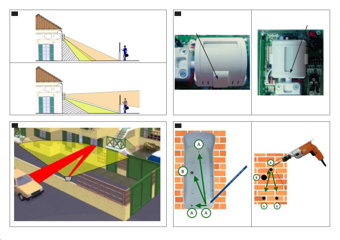
Altezza di installazione B1 e Orientamento B2
Attraversamento dell'area di rilevazione
B3 Il sensore rileva agevolmente in tutta la portata
B4Il sensore potrebbe rilevare a distanza inferiore della
portata massima
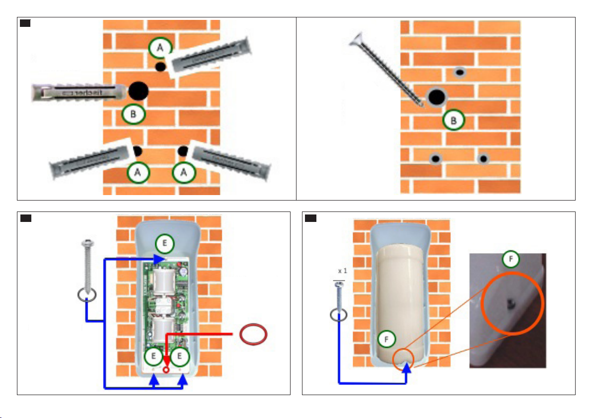
Una volta fissato il sensore, per orientare le testine è consi-
gliabile allentare leggermente il serraggio delle viti degli snodi.
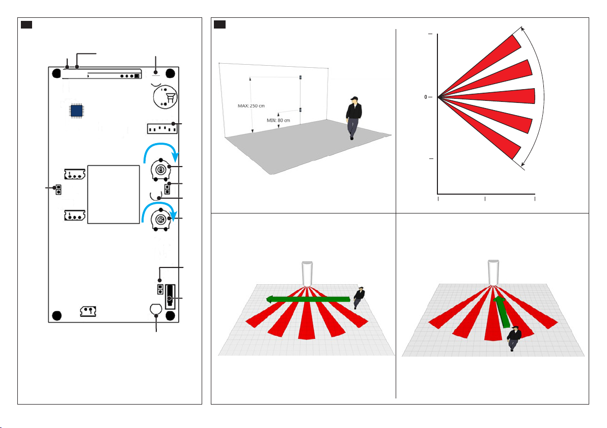
Regolazione della portata C
L’area di rilevazione è quella in cui entrambe le tecnologie
(infrarosso 1 e microonda 2) rilevano. Pertanto è neces-
sario regolare sia l’orientamento che la portata di entrambe
le testine in modo che le due aree di rilevazione siano il più
possibile coincidenti.
NOTA. Seguire l'ordine di regolazione indicato di seguito.
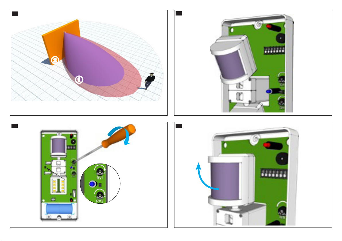
Regolazione dell'infrarosso
1- Impostare DIP7 a seconda della della dimensione dell'area
da proteggere;
2- Impostare il DIP5 su ON e DIP6 su OFF per abilitare il walk
test del solo infrarosso. Il LED DL1 (infrarosso) si accenderà
fisso mentre il LED DL3 (allarme/trasmissione) si accenderà
ad ogni rilevazione dell'infrarosso.
3- Posizionare al MASSIMO il trimmer RV1 D.
4- Orientare la testa infrarosso in direzione dell’area da co-
prire E.
5- Regolare il sensore infrarosso muovendosi all’interno
dell’area di rilevazione: il LED DL3 (blu) si accenderà quando
l’infrarosso rileverà il passaggio.
Se la portata non è quella desiderata alzare gradualmente
la testa dell'infrarosso Fe diminuirne la regolazione G.
Ripetere i test fino a raggiungere la portata desiderata H2.
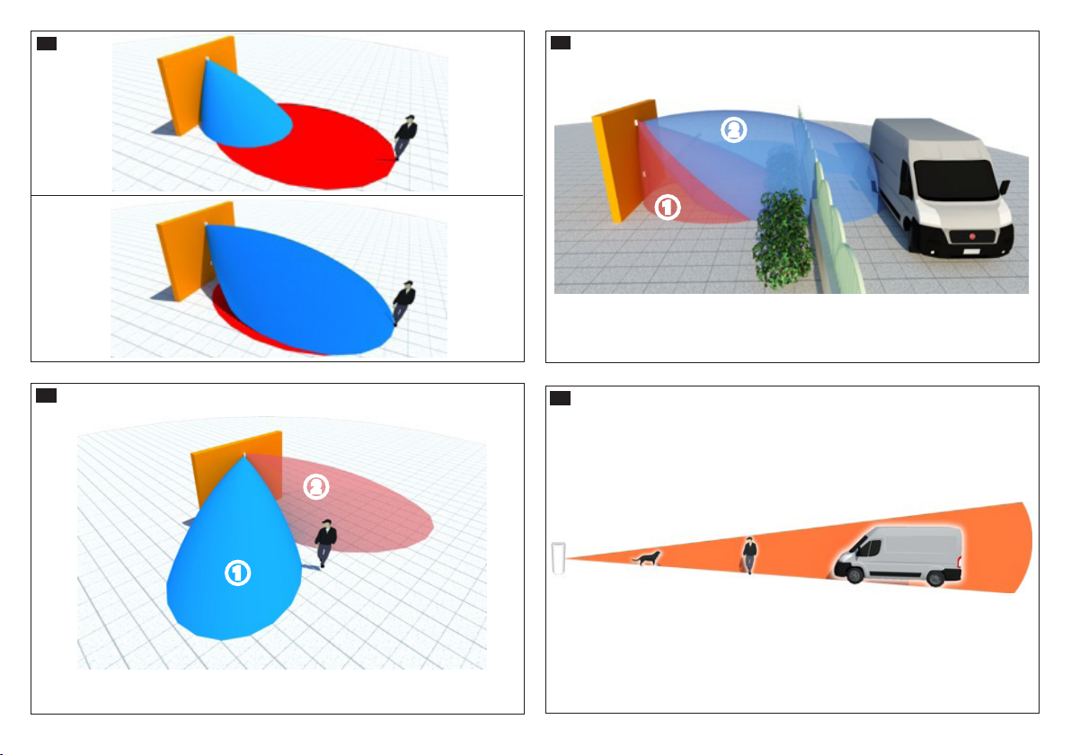
Regolazione microonda
1- Impostare il DIP5 su OFF e DIP6 su ON per abilitare il
walk test della sola microonda. Il LED DL2 (microonda) si
accenderà fisso mentre il LED DL3 (allarme/trasmissione) si
accenderà ad ogni rilevazione della microonda.
La regolazione della microonda è indipendente da quella
dell' infrarosso e la posizione di DIP7 non interviene sulla
regolazione della microonda.

10 - FA00489M4A-ver.1-03/2017
2- Regolare il sensore microonda muovendosi all’interno
dell’area di rilevazione: il LED DL3 (blu) si accenderà quando
la microonda rileverà il passaggio.
Se la portata non è quella desiderata alzare gradualmente la
testa della microonda Ie diminuirne J.
Ripetere i testi fino a raggiungere la portata desiderata K2.
☞ Il soggetto può attraversare le aree senza provocare al-
larme perché non viene rilevato da entrambe le tecnologie
contemporaneamente L.
L’area di rilevazione della microonda M2 è più grande di
quella infrarosso M1.
Si può avere un falso allarme a causa dell’attivazione non
voluta dell’infrarosso (ad esempio dal movimento di foglie)
e della microonda che rileva oltre l’area desiderata (ad
esempio dal furgone oltre la recinzione) M.
Installazione del sensore
Il sensore infrarosso è sensibile alla “quantità di calore”
emessa da un corpo in movimento. La portata massima del
sensore (espressa in metri) è riferita ad un corpo umano ed è
pertanto una misura relativa N.
Regolazione della sensibilità
Ruotare completamente in senso orario i trimmer di rego-
lazione (RV1 e RV2) ed orientare le testine il più possibile
verso il basso. Diminuire progressivamente la sensibilità e
l'inclinazione delle testine fino ad ottenere una rilevazione
solo nell’area che si intende proteggere.
Una volta terminata l’operazione di orientamento, chiudere a
fondo le viti degli snodi.
Nota. Il coperchio del sensore attenua del 30% la lunghezza
del fascio IR. Il sensore sara’ attivo e funzionante solo dopo
la fase di stabilizzazione dall’accensione; durante questa
fase non sostare o muoversi entro l’area di rilevazione.
Indicazioni per l'uso all'esterno del sensore
La testa di rilevazione IR deve essere orientata in modo che
il fascio sia orientato verso il basso O1 o al massimo pa-
rallelo al pavimento, mai verso l’alto O2. Questo per evi-
tare che, durante il giorno, i raggi solari diretti accechino il
modulo di rilevazione IR, compromettendo il buon funziona-
mento del sensore.
Le due teste (IR e microonda) devono essere orientate in
modo da formare due fasci sovrapposti.
Piccole variazioni nella posizione delle testine corrispondono
a notevoli variazioni (a distanza di 18 m) delle aree di rileva-
zione dei fasci (uno spostamento laterale di 1° della testina
corrisponde allo spostamento dei fasci di circa 30 cm a 18
m). Non orientare i fasci verso superfici riflettenti P.
Oscuramento parziale dell'infrarosso
Nel caso l'area di rilevazione sia troppo estesa oppure ci sia la
presenza di rami, tende, vetrate, etc. è consigliabile masche-
rare la parte laterale del fascio di rilevazione, vincolandolo alle
sole zone stabili dell’area da proteggere.
Nella confezione del sensore è incluso un coprilente in pla-
stica da applicare sulla testa IR per ottenere una rilevazione
ad eetto tenda. Con tale coprilente, la apertura del fascio di
rilevazione della lente viene ridotto a soli 20°, mantenendo la
stessa portata.
Il coprilente va inserito ad incastro sulla testina facendo at-
tenzione che le due bandelle laterali siano correttamente
incastrate nelle due scanalature della testina Q1 e che il
coprilente rimanga ben saldo alla testina Q2.
Montaggio
Utilizzando la visiera segnare la posizione dei fori di fissag-
gio R1.
Forare la parete R2, introdurre i tasselli necessari S1e
avvitare la vite di regolazione tamper al tassello S2 facen-
do sporgere la testa di circa 9÷10 mm. Rompere il settore
T, far passare i cavi attraverso il passacavo Ufacendo
attenzione a non tagliare la membrana ed eettuare i col-
legamenti V.
Fissare il sensore e la visiera utilizzando le viti in dotazione,
aggiungendo gli o-ring rossi o neri nell'apposita sede W.
Inserire il coperchio sulla base partendo dalla parte superio-
re e fissarlo utilizzando l'apposita vite con l'o-ring nero X.
Il prodotto è conforme alle direttive di riferimento vigenti.
Dismissione e smaltimento. Non disperdere nell’ambiente
l’imballaggio e il dispositivo alla fine del ciclo di vita, ma
smaltirli seguendo le norme vigenti nel paese di utilizzo del
prodotto. I componenti riciclabili riportano simbolo e sigla
del materiale.
I DATI E LE INFORMAZIONI INDICATE IN QUESTO MANUALE
SONO DA RITENERSI SUSCETTIBILI DI MODIFICA IN QUALSI-
ASI MOMENTO E SENZA OBBLIGO DI PREAVVISO.LE MISURE,
SE NON DIVERSAMENTE INDICATO, SONO IN MILLIMETRI.

11 - FA00489M4A-ver.1-03/2017
ENGLISH
General Precautions
Important people-safety instructions: READ CAREFUL-
LY!• Installing, programming, commissioning and mainte-
nance must only be done by qualified, expert sta and in
full compliance with the applicable law. • Wear anti-static
footwear and clothing when working on the control board.
• Keep these precautions. • This product should only be
used for the purpose for which it was explicitly designed.
There is danger of the battery exploding if it is replaced
with the wrong type. • The batteries, once their life-cycle is
exhausted, must not be thrown among the non-separated
garbage, but rather, collected and sent to a proper disposal
center. • Keep the batteries away from children's reach. • If
swallowed, seek immediate medical attention.
Description
Double-technology- passive infrared and microwave - ra-
dio-based, outdoor sensor.
The sensor is removal-protected by a built-in tamper-proof
system.
Description of parts B
1 Signaling LED
B Dip-switch
C Jumpers
D Potentiometer for setting
the infrared beam
E Potentiometer for setting
the micro-waves
F Anti-removal Tamper
LED legend
LEDs Color Meaning
DL1 Red IR detection
DL2 Red Microwave detection
DL3 Blue Alarm
DL4 Red Learning
DL5 Green Learning
Description of Jumpers
JP1 Tamper Enabling/disabling
OPEN Enabled CLOSED Disabled
JP2 Anti-Tampering Enabling/disabling
OPEN Enabled CLOSED Disabled
JP3 Enabling/disabling the DL3 alarm LED
OPEN Disabled CLOSED Enabled
Dip-switch description
DEFAULT
DIP1 Supervision
ON Enabled OFF Disabled
DIP2 (Radio test)
ON Enabled (transmits
every second) OFF
Disabled. Normal ope-
ration
DIP3 Operating modes
ON Test OFF Normal
Only switch DIP when there is no detection (if the LEDs are
enabled, switch the DIP-switch when they are all opened).The
sensor confirms switching into either test or normal mode, by
sounding o:
- TEST -> NORMAL: some quick "beeps"
- NORMAL -> TEST: long "beep"
If no sound is emitted this means that the sensor did not
switch to the chosen mode: in this case repeat the switching
of DIP3.
DIP4 Adjusting LEDs and BUZZER
ON DL1, DL2 and BUZZER
enabled. OFF
DL1, DL2 and BUZ-
ZER disabled. DL3 is
controlled by JP3. Use
this mode during nor-
mal operating mode
to increase the bat-
tery life.
DIP5-DIP6 Walk test
OFF Normal operation ON IR Walk Test ope-
ration (DL1 is on
permanently)
OFF
ON MW Walk Test operation (DL2 is on permanently)
OFF
The Walk Tests are for making adjustments to the sensor's
detection area. The infrared and microwave adjustments are
independent.
DIP7 IR range
ON
Max range about 18 m.
Adjsuting the max ran-
ge (via RV1) = about 9
÷ 18 m
OFF
Max range about
12 m. Max range
adjustment (via RV1)
= about 3 ÷ 12 m
Each time DIP7 is switched, wait 10 to 20 seconds.
Technical data
Type PXWDTVE
Power supply two 3V, CR123A,
Lithium batteries
Frequency (MHz) 433.92/868.65
Absorption when on standby (uA) 40
Absorption when alarm is triggered
(mA) < 80
Radio signal power (dBm) < 10
Microwave frequency (GHz) 24
Maximum range at 25 °C (m)* 12
Minimum range at 25 °C (m)* 3

12 - FA00489M4A-ver.1-03/2017
Type PXWDTVE
Life expectancy (years) ** 2
Working temperature (°C) -40 / +50
Dimensions (mm) 190x85x75
Protection rating (IP) 54
Impact resistance (IK) 10
EN50131-1,EN50131-2-4 Grade 2,EN50131-5-3,EN50131-
6: Type C, EN50130-5, Environmental Class III
* This is the time interval within which the two IR heads must
activate the microwaves and detect an alarm.
** The life expectancy of the sensor's batteries is inversely
proportional to the number of detections carried out (regard-
less of whether the alarm system is armed or not). If the
sensor is fitted in zones with high passage frequencies, the
batteries' life is reduced.
Potentiometers
DRV1:adjusting the detection range of the upper, infrared
head. Turn clockwise to increase the range.
E RV2: adjusting the detection range of the lower, microwave
head. Turn clockwise to increase the range.
NOTE. Before powering up the sensor, make sure that the
RV1 and RV2 are set to their maximum range, that is, ful-
ly turned clockwise. Contrarily, the sensor could receive a
signal that is too weak or not receive it at all: the LEDs will
not light up.
Powering on
Turn the potentiometers clockwise. Set DIP1, DIP2, DIP5, DIP6
to OFF; DIP3, DIP4 to ON and DIP7 as you like. Open the JP1
jumper and close the JP2 and JP3 jumpers and power up the
sensor.
The settings must then be modified with the power supply on
The sensor is ready for initiation, which will last two minutes.
Initiation
Power up the sensor. The LEDs DL1 and scales DL2 light up
for a few seconds and then switch o: a few beeps confirm
that the initialization has been complete.
To re-initialize the sensor, cut o the power, press the tamper
(JP1 = OPEN) and power up the sensor again.
You can interrupt the initialization at any time by keeping
pressed the tamper (JP1 = OPEN) for a few seconds until the
LEDs switch o. Release the tamper button.
TEST or NORMAL mode
TEST mode (DIP3 = ON)
This mode transmits the alarm each time movement is de-
tected. The sensor automatically exits TEST mode after about
five minutes, even without setting DIP3 to OFF.When the LEDs
light up and you hear the beeps, it means that mode has
switched from TEST to NORMAL.
NORMAL mode (DIP3 = OFF)
In this mode, after detecting and sending an alarm, the sensor
waits for 120 seconds of "quiet time". This time cannot be
changed.
If during said "quiet time" NO detection takes place, the sen-
sor returns to its active state and is ready for another detec-
tion.
NORMAL mode is for lower power consumption and greater
battery life. Set DIP3 to ON: a long beep confirms the switch-
ing from NORMAL to TEST mode.
Learning
Power up the sensor and wait for the initialization phase to
end. It does not matter whether the sensor is in TEST or NOR-
MAL (DIP3) mode.
Open the JP1 jumper and make sure that the control unit is
in learning mode.
Press and release, three times, the tamper's lever button for
five seconds, maximum. During the learning phase, the red
DL4 and green DL5 fitted on the radio expansion, will start
flashing. Once the learning phase is over, the green DL5 will
light up for three seconds; in case of any errors, the red DL4
will light up.
Installation height B1 and orientation B2
Crossing the detection area
B3 The sensor easily detects across the entire range
B4The sensor may detect at a shorter distance than its
max range. Once the sensor is fastened, to direct the heads
we suggest slightly loosening the joint screws.
Adjusting the range C
The detection area is that in which both technologies, that is
infrared 1 and microwave 2are detecting. So it is neces-
sary to adjust bot the orientation and range of both heads so
that the two detection areas coincide as much as possible.
NOTE. Follow the adjustment order explained below.
Adjusting the infrared
1- Set DIP7 depending on the dimensions of the area to pro-
tect;
2- Set DIP5 to ON and DIP6 to OFF to enable the walk test only
for the infrared sensor. The DL1 infrared LED will light up and
stay lit while the DL3 alarm and transmission LED will light up
at each infrared detection.
3- Postion trimmer RV1 to MAXIMUM D.
4- Turn the infrared head towards the area to protect E.
5- Adjust the infrared sensor by moving around within the de-
tection area: the blue DL3 LED will light up when the infrared
sensor detects a passage.
If the range is not the one you need, gradually raise the infra-
red head Fand diminish the adjustment G.
Repeat the test until you obtain the desired range H2.
Adjusting the microwave
1- Set DIP5 to OFF and DIP6 to ON to enable only the micro-
wave walk test. The DL2 LED (microwave) will turn on and
stay on while the DL3 LED (alarm/transmission) will turn on
with each microwave detection.
Adjusting the microwave is independent from adjusting the
infrared and the position of DIP7 does not aect the micro-
wave adjusting.
2- Adjust the microwave sensor by moving around within
the detection area: the blue DL3 LED will light up when the
microwave sensor detects a passage.
If the range is not the desired one, gradually raise the mirco-
wave head Iand reduce its J.
Repeat the tests until you obtain the desired range K2.

13 - FA00489M4A-ver.1-03/2017
☞ The subject can walk through the areas without trigger-
ing an alarm because it is not detected by both technolo-
gies simultaneously L.
The detection area of the microwave M2 is greater than
that of the microwave M1.
A false alarm could be caused by an unwanted infrared
activation (like when leaves move in the wind) and micro-
wave activation that detects beyond the protected area (like
when a van drives by beyond the fence) M.
Installing the sensor
The infrared sensor is sensitive to the amount of heat given
o by a moving body.
The maximum range of the sensor, expressed in meters, re-
fers to a human body and is thus a relative measurement N.
Adjusting the sensitivity
Turn the RV1 and RV2 adjusting trimmers completely clock-
wise and orient the heads downwards as much as possible.
Progressively diminish the sensitivity and inclination of the
heads until they only detect inside the area which you want
to protect.
Once the orientation operation is concluded, tighten the joint
screws.
Please note.The sensor's cover diminishes the length of the
IR beam by 30%.
The sensor will be active and operational after powering up,
only after the stabilization phase; during this phase, do not
stand or move around the detection area.
Instructions for using the sensor outdoors
The IR detection head must be turned so that the beam is
facing downwards O1 or, at most, parallel to the floor, but
never upwards O2This is to prevent that, during the day,
direct sun rays can blind the IR detection module, thus com-
promising the proper operation of the sensor.
The two IR and microwave heads must be oriented so as to
form two overlapping beams.
Small variations in the positioning of the heads translate into
significant variations - at 18 meters - of the beams' detec-
tion areas. A lateral variation of 1° of the head translated to
a moving the beam by 30 centimeters at 18 meters. Do not
turn the beams towards reflective surfaces P.
Partially masking the infrared
If the detection area is too extensive or has branches, drapes,
window panes, and so on, it is advisable to mask the lateral
part of the detection beam, to force it to detect only in the area
it needs to protect.
The sensor's package contains a plastic lens cap to fit onto
the IR head to obtain a curtain eect detection.
With the lens cap, the beam's detection breadth is diminished
to just 20%, while maintaining the same range.
The lens cover should be snapped onto the head, being care-
ful that the two lateral bands be properly fitted into the head's
grooves Q1 and that the lens cover is firmly in place on the
head Q2.
Mounting
Using the visor to mark the position of the fastening holes
R1.
Drill the wall R2, fit anchors if necessary S1and tighten
the tamper adjusting screw into the dowel S2 so that the
head juts out by about 9 to 10 mm.
Break sector T, thread the cables through the cable gland
Ubeing careful not to cut the membrane and then connect
up the cables V.
Fasten the sensor and the visor by using the supplied
screws, and add the red or back O-rings to their correspond-
ing housing W.
Fit the cover to the base by starting from the upper part and
fasten it using the corresponding screw and black O-ring X.
This product complies with the law.
Decommissioning and disposal. Dispose of the packaging
and the device at the end of its life cycle responsibly, in
compliance with the laws in force in the country where the
product is used.The recyclable components are marked with
a symbol and the material's ID marker.
THE DATA PRESENTED IN THIS MANUAL MAY BE CHANGED,
AT ANY TIME, AND WITHOUT NOTICE. MEASUREMENTS,
UNLESS OTHERWISE STATED, ARE IN MILLIMETERS.

14 - FA00489M4A-ver.1-03/2017
FRANÇAIS
Instructions générales
Instructions importantes pour la sécurité des personnes :
À LIRE ATTENTIVEMENT ! • L’installation, la programmation,
la mise en service et l'entretien doivent être eectués par
du personnel qualifié et dans le plein respect des normes en
vigueur. • Porter des vêtements et des chaussures antista-
tiques avant d'intervenir sur la carte électronique.
• Conserver ces instructions. • Ce produit ne devra être desti-
né qu'à l'utilisation pour laquelle il a été expressément conçu.
Ne remplacer la pile usagée que par une pile compatible
afin d'éviter tout risque d'explosion. • Ne pas jeter les piles
à la poubelle au terme de leur cycle de vie, mais les collec-
ter séparément en vue d'un recyclage correct. • Conserver
les piles hors de portée des enfants. • En cas d'ingestion,
consulter immédiatement un médecin.
Description
Capteur radio d’extérieur bi-technologie (infrarouge passif et
micro-onde). L’alarme est générée uniquement si les techno-
logies eectuent la même détection.
Un système anti-arrachement incorporé confère au capteur
un haut niveau de résistance au vandalisme.
Description des parties B
1 Voyants led de signalisation
B Micro-interrupteurs
C Cavaliers
D Potentiomètre pour le
réglage de l’infrarouge
E Potentiomètre pour le
réglage de la micro-onde
F Autoprotection anti-
arrachement
Légende des leds
LED Couleur Signification
DL1 Rouge Détection IR
DL2 Rouge Détection micro-onde
DL3 Bleu Alarme
DL4 Rouge Apprentissage
DL5 Vert Apprentissage
Description des cavaliers
JP1 Activation/désactivation autoprotection
OUVERT Activé FERMÉ Désactivé
JP2 Activation/désactivation autoprotection anti-arrache-
ment
OUVERT Activé FERMÉ Désactivé
JP3 Activation/désactivation DL3 LED d’alarme
OUVERT Désactivé FERMÉ Activé
Description des micro-interrupteurs
PAR DÉFAUT
DIP1 Contrôle
ON Activé OFF Désactivé
DIP2 (Test radio)
ON Activé (transmet toutes
les secondes) OFF
Désactivé (fonction-
nement normal)
DIP3 Mode de fonctionnement
ON Test OFF Normal
Ne déplacer le DIP3 qu'à défaut de détection (si les voyants
sont activés, déplacer le DIP quand ils sont tous éteints). Le
capteur confirme le passage à la modalité TEST ou NORMAL
par l'émission de sons :
- TEST -> NORMAL : quelques bips rapides
- NORMAL -> TEST : bip long
L'absence de son indique que le capteur N'est PAS entré dans
la modalité sélectionnée. Si tel est le cas, déplacer à nouveau
le DIP3.
DIP4 Réglage VOYANTS et BUZZER
ON DL1, DL2 et
BUZZER activés. OFF
DL1, DL2 et BUZZER dé-
sactivés. DL3 est géré par
JP3. Utiliser cette modalité
durant le fonctionnement
normal pour augmenter la
durée des piles.
DIP5-DIP6 Essai de marche
OFF
Fonctionnement
normal
ON Fonctionnement
essai de marche
IR (DL1 allumé en
permanence)
OFF
ON Fonctionnement essai de marche MW (DL2 allu-
mé en permanence)
OFF
Les essais de marche permettent le réglage de la zone de
détection du capteur. Les réglages infrarouge et micro-onde
sont indépendants.
DIP7 Plage IR
ON
Portée maximale envi-
ron 18 m ; réglage de
la portée maximale
(par RV1) = environ 9
- 18 m
OFF
Portée maximale envi-
ron 12 m ; réglage de
la portée maximale
(par RV1) = environ
3 - 12 m
À chaque déplacement du DIP7, attendre de 10 à 20 s.
Données techniques
Type PXWDTVE
Alimentation 2 piles au lithium 3 V
(CR123A)
Fréquence (MHz) 433.92/868.65
Absorption en mode veille (uA) 40
Absorption en état d'alarme (mA) < 80
Puissance signal radio (dBm) < 10
Fréquence micro-onde (GHz) 24
Portée maximale à 25°C (m)* 12
Portée minimale à 25°C (m)* 3
Autonomie estimée (ans) ** 2

15 - FA00489M4A-ver.1-03/2017
Type PXWDTVE
Température de fonctionnement (°C) -40 à +50
Dimensions (mm) 190x85x75
Degré de protection (IP) 54
Résistance à l'impact (IK) 10
EN50131-1,EN50131-2-4 Grade 2,EN50131-5-3,EN50131-
6 : Type C, EN50130-5, Classe d'environnement III
* Il s’agit de l'intervalle de temps au cours duquel les deux
têtes IR doivent activer la micro-onde et détecter l’alarme.
** La durée estimée des piles du capteur est inversement
proportionnelle au nombre de détections eectuées (indé-
pendamment de l'activation ou non du système d'alarme).
L'installation du capteur dans des zones à trafic intense réduit
l'autonomie de la pile.
Potentiomètres
D RV1 : réglage de la portée de détection de la tête supé-
rieure (infrarouge). Tourner dans le sens horaire pour en aug-
menter la portée.
ERV2 : réglage de la portée de détection de la tête inférieure
(micro-onde).Tourner dans le sens horaire pour en augmenter
la portée.
REMARQUE : avant de mettre le capteur sous tension,
s'assurer que RV1 et RV2 sont bien réglés sur la portée
maximale (complètement tournés dans le sens horaire).
Dans le cas contraire, le capteur pourrait recevoir un signal
trop faible ou ne pas le recevoir du tout : les VOYANTS ne
s'allumeront pas.
Allumage
Tourner les potentiomètres en sens horaire. Configurer les
DIP1, DIP2, DIP5, DIP6 sur OFF ; DIP3, DIP4 sur ON et DIP7 au
choix. Ouvrir le cavalier JP1 et fermer les cavaliers JP2 et JP3
puis alimenter le capteur.
La modification des configurations ne requiert pas la mise
hors tension. Le capteur est prêt pour l'initialisation qui durera
2 minutes.
Initialisation
Alimenter le capteur. Les voyants DL1 et DL2 s’allument pen-
dant quelques secondes et s’éteignent : quelques bips confir-
ment l'initialisation eective.
Pour réinitialiser le capteur, le mettre hors tension, appuyer
sur l’autoprotection (JP1 = OUVERT), et le remettre sous ten-
sion.
Il est possible d'interrompre l'initialisation à tout moment
en maintenant la touche autoprotection enfoncée (JP1 =
OUVERT) pendant quelques secondes jusqu’à l’extinction des
voyants. Relâcher la touche de l’autoprotection.
Modalité TEST ou NORMAL
Mode TEST (DIP3 = ON)
Ce mode transmet l’alarme à chaque détection de mouve-
ment. Le capteur sort automatiquement de la modalité TEST
au bout de 5 minutes environ, même sans positionner le DIP3
sur OFF. L'allumage des voyants et un bip confirment le pas-
sage du mode TEST au mode NORMAL.
Mode NORMAL (DIP3 = OFF)
Dans cette modalité - après une détection et l'envoi d'une
alarme - le capteur attend un « temps de calme » (120
secondes non modifiable) avant de considérer une nouvelle
alarme.
À défaut de détection durant le temps de calme, le capteur est
à nouveau activé et prêt pour une autre détection.
Le mode NORMAL permet une réduction de la consommation
et une plus longue durée de vie des piles. Positionner le DIP3
sur ON : un bip prolongé confirme le passage du mode NOR-
MAL au mode TEST.
Apprentissage
Mettre le capteur sous tension et attendre la fin de la phase
d’initialisation. Le mode de fonctionnement du capteur - TEST
ou NORMAL (DIP3) - est indiérent.
Ouvrir le cavalier JP1 et s’assurer que la centrale est bien en
mode apprentissage.
Enfoncer et relâcher 3 fois de suite en 5 secondes maximum
le bouton à levier de l'autoprotection. Durant la phase d’ap-
prentissage, les voyants DL4 (rouge) et DL5 (vert) présents sur
l’expansion radio clignoteront.Au terme de la phase d’appren-
tissage, le voyant DL5 (vert) s’allumera pendant 3 secondes
; en cas d’erreur, c’est le voyant DL4 (rouge) qui s’allumera.
Hauteur d'installation B1 et Orientation B2
Franchissement de la zone de détection
B3 Le capteur détecte facilement en couvrant toute la
plage de portée
B4Le capteur pourrait détecter à une distance inférieure
par rapport à la portée maximale
Après avoir fixé le capteur, il est conseillé de desserrer légère-
ment les vis des rotules pour l'orientation des têtes.
Réglage de la portée C
La zone de détection est celle où les deux technologies (infra-
rouge 1 et micro-onde 2) détectent. Il faut par conséquent
régler aussi bien l'orientation que la portée des deux têtes de
manière à ce que les deux zones de détection coïncident le
plus possible.
REMARQUE : suivre l'ordre de réglage indiqué ci-après.
Réglage de l'infrarouge
1- Configurer le DIP7 en fonction des dimensions de la zone
à protéger.
2- Configurer le DIP5 sur ON et le DIP6 sur OFF pour activer
l'essai de marche uniquement sur l'infrarouge. Le VOYANT
DL1 (infrarouge) s'allumera en permanence tandis que le
VOYANT DL3 (alarme/transmission) s'allumera à chaque dé-
tection de l'infrarouge.
3- Tourner le trimmer RV1 DCOMPLÈTEMENT sur +.
4- Orienter la tête de l'infrarouge vers la zone à couvrir E.
5- Régler le capteur infrarouge en se déplaçant dans la zone
de détection : le VOYANT DL3 (bleu) s'allumera lorsque l'infra-
rouge détectera le passage.
Si la portée n'est pas correcte, lever graduellement la tête de
l'infrarouge Fet en diminuer le réglage G.
Répéter les essais jusqu'à obtention de la portée souhaitée
H2.
Réglage de la micro-onde
1- Configurer le DIP5 sur OFF et le DIP6 sur ON pour activer

16 - FA00489M4A-ver.1-03/2017
l'essai de marche uniquement sur la micro-onde. Le VOYANT
DL2 (micro-onde) s'allumera en permanence tandis que le
VOYANT DL3 (alarme/transmission) s'allumera à chaque dé-
tection de la micro-onde.
Le réglage de la micro-onde ne dépend pas de celui de l'infra-
rouge et la position du DIP7 n'intervient pas sur le réglage de
la micro-onde.
2- Régler le capteur micro-onde en se déplaçant dans la zone
de détection : le VOYANT DL3 (bleu) s'allumera lorsque la
micro-onde détectera le passage.
Si la portée n'est pas correcte, lever graduellement la tête de
la micro-onde Iet en diminuer le réglage J.
Répéter les essais jusqu'à obtention de la portée souhaitée
K2.
☞ Le sujet peut traverser les zones sans provoquer
d'alarme du fait qu'il n'est pas détecté en même temps par
les deux technologies L.
La zone de détection de la micro-onde M2est plus grande
que celle de l'infrarouge M1.
Il peut y avoir fausse alarme suite à l'activation non voulue
de l'infrarouge (provoquée par exemple par le mouvement
de feuilles) et de la micro-onde qui détecte au-delà de la
zone souhaitée (provoquée par exemple par le fourgon de
l'autre côté de la clôture) M.
Installation du capteur
Le capteur infrarouge est sensible à la « quantité de chaleur
» émise par un corps en mouvement. La portée maximale du
capteur (exprimée en mètres) se réfère à un corps humain,
raison pour laquelle il s'agit d'une mesure relative N.
Réglage de la sensibilité
Tourner complètement les trimmers de réglage (RV1 et RV2)
dans le sens horaire et orienter les têtes le plus possible vers
le bas. Réduire progressivement la sensibilité et l'inclinaison
des têtes jusqu'à obtenir une détection uniquement dans la
zone à protéger.
Au terme de l'opération d'orientation, serrer à fond les vis des
rotules.
Remarque. le couvercle du capteur atténue de 30% la lon-
gueur du faisceau IR. Le capteur ne sera activé et ne fonction-
nera qu'au terme de la phase de stabilisation après l'allumage
; durant cette phase, ne pas stationner ni ne se déplacer dans
la zone de détection.
Indications sur l'utilisation du capteur à l'extérieur
La tête de détection IR doit être orientée de manière à ce
que le faisceau soit dirigé vers le bas O1ou au maximum
parallèle au sol, jamais vers le haut O2. Ceci afin d'éviter,
le jour, que les rayons solaires directs n'aveuglent le module
de détection IR en compromettant le bon fonctionnement du
capteur.
Les deux têtes (IR et micro-onde) doivent être orientées de
manière à former deux faisceaux superposés.
La moindre variation au niveau de la position des têtes cor-
respond à une grande variation (à une distance de 18 m) des
zones de détection des faisceaux (un déplacement latéral
de 1° de la tête correspond au déplacement des faisceaux
d'environ 30 cm à 18 m). Ne pas orienter les faisceaux vers
des surfaces réfléchissantes P.
Obscurcissement partiel de l'infrarouge
En cas de zone de détection trop étendue ou présentant des
branches d'arbres, des stores, des surfaces vitrées, etc., il est
conseillé de masquer la partie latérale du faisceau en en limi-
tant la détection uniquement aux espaces stables de la zone
à protéger.
L'emballage du capteur comprend également un couvre-len-
tille en plastique à appliquer sur la tête IR pour obtenir une
détection à eet rideau.Avec ce couvre-lentille, l'ouverture du
faisceau de détection de la lentille est réduite à 20° seulement
tout en maintenant la même portée.
Appliquer le couvre-lentille par encastrement sur la tête en
contrôlant que les deux bandes latérales s'engagent correcte-
ment dans les deux rainures de la tête Q1 et que le couvre-
lentille est bien fixé à la tête Q2.
Montage
À l'aide de la visière, noter la position des trous de fixation
R1.
Percer le mur R2, introduire les chevilles nécessaires S1
et visser la vis de réglage de l'autoprotection à la cheville
S2 en faisant dépasser la tête d'environ 9-10 mm. Rompre
le secteur T, faire passer les câbles à travers le passe-câble
Uen ayant soin de ne pas couper la membrane, puis eec-
tuer les branchements V.
Fixer le capteur et la visière à l'aide des vis fournies en appli-
quant les joints toriques rouges ou noirs dans le logement
prévu à cet eet W.
Appliquer le couvercle sur la base en partant de la partie
supérieure et le fixer à l'aide de la vis spécifique avec joint
torique noir X.
Le produit est conforme aux directives de référence en
vigueur.
Mise au rebut et élimination. Ne pas jeter l'emballage et
le dispositif dans la nature au terme du cycle de vie de ce
dernier, mais les éliminer selon les normes en vigueur dans
le pays où le produit est utilisé. Le symbole et le sigle du
matériau figurent sur les composants recyclables.
LES DONNÉES ET LES INFORMATIONS CONTENUES DANS
CE MANUEL SONT SUSCEPTIBLES DE SUBIR DES MODIFI-
CATIONS À TOUT MOMENT ET SANS AUCUN PRÉAVIS. LES
DIMENSIONS SONT EXPRIMÉES EN MILLIMÈTRES, SAUF
INDICATION CONTRAIRE.

17 - FA00489M4A-ver.1-03/2017
РУССКИЙ
Общие правила безопасности
Важные правила техники безопасности: ПРОЧИТАЙТЕ ВНИ-
МАТЕЛЬНО! • Монтаж, программирование, ввод в эксплуатацию
и техническое обслуживание должны производиться квалифи-
цированным и опытным персоналом в полном соответствии с
требованиями действующих норм безопасности. • Используйте
антистатическую одежду и обувь при работе с электроникой.
• Храните данные инструкции. • Это изделие должно использо-
ваться исключительно по назначению.
Опасность взрыва при замене батарейки на элемент пита-
ния неправильного типа. • По истечении срока службы батарей-
ки должны быть собраны отдельно и переданы авторизованной
компании для последующей утилизации.Запрещается выбрасы-
вать батарейки с обычным или дифференцированным бытовым
мусором. • Держите батарейки вне досягаемости детей. • При
проглатывании элементов питания немедленно обратитесь к
врачу.
Описание
Беспроводной комбинированный (ПИК + СВЧ) датчик для на-
ружной установки.Тревожная сигнализация включается толь-
ко при одновременном срабатывании обоих детекторов.
Для защиты от несанкционированного демонтажа прибор
оборудован встроенным датчиком снятия со стены.
Основные компоненты B
1 Светодиодные индика-
торы
B Dip-переключатели
C Перемычки
D Потенциометр для ре-
гулировки инфракрасного
излучения
E Потенциометр для регу-
лировки СВЧ
F Датчик снятия со стены
УСЛОВНЫЕ ОБОЗНАЧЕНИЯ ИНДИКАТОРА
LED Цвет Значение
DL1 Красный ИК-датчик
DL2 Красный СВЧ-датчик
DL3 Синий Тревожная сигнализация
DL4 Красный Определение
DL5 Зеленый Определение
Описание перемычек
JP1 Включение/выключение датчика саботажа
ОТКРЫТО Включено ЗАКРЫТО Выключено
JP2 Включение/выключение датчика снятия со стены
ОТКРЫТО Включено ЗАКРЫТО Выключено
JP3 Включение/выключение светодиодного индикатора тре-
вожной сигнализации DL3
ОТКРЫТО Выключено ЗАКРЫТО Включено
Описание DIP-переключателей
ПО УМОЛЧАНИЮ
DIP1 Контроль
ON Включен OFF Отключен
DIP2 (проверка радиосигнала)
ON Включено (передает
каждую секунду) OFF
Выключено Нор-
мальная работа
DIP3 Режим работы
ON Тестирование OFF Нормальный
Перемещайте DIP3, только когда детекторы не работают
(если светодиодные индикаторы светятся, переместите DIP-
переключатель только после того, как они погаснут). Датчик
подтвердит переход в режим тестирования или режим нор-
мальной работы посредством звуковых сигналов:
- ТЕСТИРОВАНИЕ -> НОРМАЛЬНАЯ РАБОТА: серия коротких
звуковых сигналов;
- НОРМАЛЬНАЯ РАБОТА -> ТЕСТИРОВАНИЕ: длинный звуковой
сигнал.
Полное отсутствие звуковых сигналов означает, что датчик
НЕ перешел в выбранный режим. В этом случае переместите
DIP3 еще раз.
DIP4 Регулировка светодиодных индикаторов и ЗУММЕРА
ON DL1, DL2
и ЗУММЕР
включены OFF
DL1, DL2 и ЗУММЕР выклю-
чены. DL3 управляется пере-
мычкой JP3. Рекомендуется
использовать данный режим
при нормальной работе, что-
бы увеличить срок действия
аккумуляторных батарей.
DIP5-DIP6 Тест на движение
OFF
Нормальная ра-
бота
ON Режим "Тест на
движение" ИК (DL1
горит ровным све-
том)
OFF
ON Режим "Тест на движение" СВЧ (DL2 горит ров-
ным светом)
OFF
Тестирование дает возможность настроить зону обнаруже-
ния датчика. Регулировки ИК и СВЧ не зависят друг от друга.
DIP7 Дальность обнаружения ИК-детектора
ON
Максимальная даль-
ность обнаружения
составляет около
18 м. Диапазон регу-
лирования дальности
(посредством RV1) =
около 9 — 18м.
OFF
Максимальная даль-
ность обнаружения
составляет около
12 м. Диапазон регу-
лирования дальности
(посредством RV1) =
около 3 — 12м.
При каждом перемещении DIP7 подождите 10 - 20 сек.
Технические характеристики
Модель PXWDTVE
Электропитание 2 литиевые бата-
рейки, 3 В (CR123А)
Частота (МГц) 433,92/868,65
Потребляемый ток в режиме ожидания
(мкА) 40
Потребление при передаче сигнала (мA) < 80
Мощность радиосигнала (дБм) < 10

18 - FA00489M4A-ver.1-03/2017
Модель PXWDTVE
Частота микроволнового излучения (в
ГГц) 24
Мин. дальность обнаружения при
25 °C (м)* 12
Мин. дальность обнаружения при
25 °C (м)* 3
Расчетный срок службы (года) ** 2
Диапазон рабочих температур (°C) -40 / +50
Габаритные размеры (мм) 190x85x75
Класс защиты (IP) 54
Ударопрочность (IK) 10
EN50131-1, EN50131-2-4 класс 2, EN50131-5-3, EN50131-6:
тип C, EN50130-5, класс опасности для окружающей среды III
* Это интервал времени, в пределах которого два ИК-датчика
должны активировать микроволновый датчик и подать сигнал
тревоги.
** Расчетный срок службы батареек охранного извещателя
обратно пропорционален количеству его срабатываний (неза-
висимо от того, включена тревожная сигнализация или нет).
Если извещатель установлен в проходной зоне с высокой ин-
тенсивностью движения, срок службы батареек уменьшается.
Потенциометры
D RV1: регулировка дальности обнаружения верхней головки
(ИК-детектора). Чтобы увеличить дальность обнаружения, по-
верните ручку по часовой стрелке.
ERV2: регулировка дальности обнаружения нижней головки
(СВЧ-детектора). Чтобы увеличить дальность обнаружения,
поверните ручку по часовой стрелке.
ПРИМЕЧАНИЕ. Прежде чем подать напряжение на датчик,
убедитесь, что RV1 и RV2 установлены на максимальную
дальность обнаружения (поверните их до упора по часовой
стрелке). В противном случае на датчик может поступать
слишком слабый сигнал, или же он не будет получать вооб-
ще никакого сигнала. Светодиодные индикаторы при этом
будут оставаться выключенными.
Включение
Поверните потенциометры по часовой стрелке. Установите
DIP1, DIP2, DIP5, DIP6 в положение "ВЫКЛ"; DIP3, DIP4 в по-
ложение "ВКЛ." и DIP7 по желанию. Откройте перемычку JP1
и закройте перемычки JP2 и JP3, после чего подайе напряже-
ние на датчик. Впоследствии вы можете изменять настройки,
не отключая электропитание. После этого датчик готов к ини-
циализации, которая займет 2минуты.
Инициализация
Включите электропитание извещателя. Светодиодные ин-
дикаторы DL1 и DL2 загорятся на несколько секунд и затем
погаснут: несколько звуковых сигналов подтвердят успешную
инициализацию.
Для повторной инициализации датчика отключите электропи-
тание, нажмите на кнопку датчика саботажа (JP1 = ОТКРЫТА)
и снова подайте напряжение на датчик.
Инициализацию можно прервать в любой момент, нажав и
удерживая кнопку датчика снятия со стены (JP1 = ОТКРЫТА)
в течение нескольких секунд, пока светодиодные индикаторы
не погаснут. Отпустите кнопку датчика саботажа.
Режимы ТЕСТИРОВАНИЯ и НОРМАЛЬНОЙ РАБОТЫ
Режим ТЕСТИРОВАНИЯ (DIP3 = ВКЛ.)
Этот режим позволяет передавать тревожный сигнал при
каждом обнаружении движения. Датчик автоматически вы-
ходит из режима ТЕСТИРОВАНИЯ по истечении около 5 минут,
даже без установки DIP3 в положение "ВЫКЛ.". Последова-
тельное включение светодиодных индикаторов и звуковой
сигнал подтверждают переход от режима ТЕСТИРОВАНИЯ к
режиму НОРМАЛЬНОЙ РАБОТЫ.
Режим НОРМАЛЬНОЙ работы (DIP3 = ВЫКЛ)
В данном режиме, после обнаружения движения и генериро-
вания сигнала тревоги, извещатель ждет определенное время
(120 секунд, не изменяемых), прежде чем подать новый сиг-
нал тревоги.
Если в это время повторного обнаружения не происходит, из-
вещатель возвращается к работе в нормальном режиме, гото-
вый к обнаружению движения.
Режим НОРМАЛЬНОЙ РАБОТЫ обеспечивает меньшее потре-
бление электроэнергии и продлевает срок службы батареек.
Установите DIP3 в положение ВКЛ.: длительный звуковой
сигнал подтверждает переход из НОРМАЛЬНОГО режима в
режим ТЕСТИРОВАНИЯ.
Определение
Подайте электропитание на извещатель и дождитесь завер-
шения его инициализации. Не имеет значения, какой режим
установлен для датчика: ТЕСТИРОВАНИЯ или НОРМАЛЬНОЙ
РАБОТЫ (DIP3).
Разомкните перемычку JP1 и убедитесь в том, что контроль-
ная панель системы охранной сигнализации находится в ре-
жиме обнаружения устройства.
Трижды нажмите и отпустите кнопку датчика вскрытия в те-
чение максимум 5 секунд. Во время определения устройства
светодиодные индикаторы DL4 (красный) и DL5 (зеленый) на
модуле расширения будут мигать. По завершении определе-
ния на 3 секунды загорится светодиодный индикатор DL5 (зе-
леный); в случае ошибки загорится светодиодный индикатор
DL4 (красный).
Высота установки B1 и ориентация B2
Пересечение зоны обнаружения
B3 Датчик обнаруживает движение в пределах максималь-
ной дальности обнаружения.
B4Датчик может обнаруживать движение на расстоянии
меньше максимальной дальности обнаружения.
Для ориентации детекторов после крепления датчика реко-
мендуется слегка ослабить затяжку винтов шарнирных со-
единений.
Регулировка дальности обнаружения C
Зона обнаружения ― это зона, в которой срабатывают оба
типа детекторов (ИК 1 и СВЧ 2) Необходимо правильно рас-
положить и отрегулировать дальность каждого детектора для
того, чтобы их зоны обнаружения максимально совпадали.
ПРИМЕЧАНИЕ. Соблюдайте порядок регулировки, описан-
ный ниже.
Регулировка ИК-датчика
1 - Установите DIP7 в положение, соответствующее размерам
зоны обнаружения.
2 - Установите DIP5 в положение ON, а DIP6 ― в положение
OFF, чтобы активировать режим "тестирование" только для
ИК-детектора. Светодиодный индикатор DL1 (ИК) загорится
ровным светом, а светодиодный индикатор DL3 (сигнал тре-
воги/передачи) будет включаться при каждом срабатывании
ИК-датчика.
3 - Установите на МАКСИМУМ регулировку RV1 D.

19 - FA00489M4A-ver.1-03/2017
4 - Установите ИК-детектор в направлении зоны обнаружения
E.
5 - Отрегулируйте ИК-датчик, двигаясь в зоне обнаружения:
синий светодиодный индикатор DL3 будет загораться при об-
наружении движения.
Если дальность обнаружения вас не устраивает, постепенно
поднимайте головку ИК-датчика F, уменьшая регулировку
G.
Повторяйте тестирование, пока не установите желаемую
дальность зоны обнаружения H2.
Регулировка СВЧ-датчика
1 - Установите DIP5 в положение OFF, а DIP6 ― в положение
ON, чтобы активировать режим "тестирование" только для
СВЧ-детектора. Светодиодный индикатор DL2 (СВЧ) загорится
ровным светом, а светодиодный индикатор DL3 (сигнал тре-
воги/передачи) будет включаться при каждом срабатывании
СВЧ-датчика.
СВЧ-датчик регулируется независимо от ИК-датчика: положе-
ние DIP7 не влияет на регулировку СВЧ-датчика.
2 - Отрегулируйте СВЧ-датчик, двигаясь в зоне обнаружения:
синий светодиодный индикатор DL3 будет включаться при об-
наружении движения.
Если дальность обнаружения вас не устраивает, постепенно
поднимайте головку СВЧ-детектора I, уменьшая регулиров-
ку J.
Повторяйте процедуру тестирования, пока не установите же-
лаемую дальность зоны обнаружения K2.
☞ Субъект может пересечь зону обнаружения, не спрово-
цировав включение тревожной сигнализации, если движе-
ние не будет обнаружено двумя детекторами одновременно
L.
Зона обнаружения СВЧ-детектора M2 больше зоны обна-
ружения ИК-детектора M1.
Непроизвольное срабатывание ИК-детектора (например,
при движении листьев) и СВЧ-детектора при обнаружении
движения за пределами определенной зоны защиты (на-
пример, движения фургона за оградой) может привести к
ложному срабатыванию тревожной сигнализации M.
Установка датчика
ИК-датчик реагирует на количество тепла, излучаемого дви-
жущимся телом. Максимальная дальность обнаружения дат-
чика (выраженная в метрах) рассчитана с учетом тепла чело-
веческого тела и, следовательно, является относительной N.
Регулировка чувствительности датчика
Поверните по часовой стрелке до упора регулировки RV1 и
RV2 и направьте головки детекторов максимально вниз. По-
степенно уменьшайте чувствительность и угол наклона голо-
вок до тех пор, пока детекторы не станут обнаруживать дви-
жение только в пределах охраняемой зоны.
Завершив ориентацию, полностью закрутите винты шарнир-
ных обнаружения.
Примечание: крышка датчика на 30% уменьшает длину пуч-
ка ИК-лучей. Датчик начнет работать спустя некоторое время,
необходимое для его стабилизации после включения. Во вре-
мя этой процедуры не стойте и не ходите в зоне обнаружения.
Инструкции по использованию датчика в уличных усло-
виях
Головка ИК-датчика должна быть направлена так,чтобы пучок
лучей был обращен вниз O1или находился на максималь-
но близком расстоянии параллельно земле. Ни в коем случае
он не должен быть направлен вверх O2. Это требуется для
того, чтобы в течение дня солнечные лучи не влияли на ИК-
датчик, компрометируя его исправность.
Два датчика (ИК и СВЧ) должны быть расположены так, чтобы
их пучки накладывались друг на друга.
Небольшие изменения в расположении головок детекторов
(при дальности 18м) влекут за собой значительные измене-
ния зон обнаружения (боковое смещение головки детектора
на 1° соответствует смещению пучков на около 30 см при
дальности обнаружения 18м). Не направляйте пучки датчиков
в сторону отражающих поверхностей P.
Частичное затемнение ИК-датчика
В случае большой протяженности зоны обнаружения и при
наличии ветвей деревьев, занавесей, больших окон и т.п. ре-
комендуется замаскировать боковую часть пучка детектора,
выделив только узкие неподвижные зоны охраняемой тер-
ритории.
Датчик поставляется в комплекте с пластиковой крышкой,
которую необходимо установить на головку ИК-датчика для
создания зоны обнаружения типа "штора". С помощью такой
крышки апертурный угол линзы уменьшается до 20° при той
же дальности.
Крышку необходимо вставить до щелчка, внимательно следя
за тем, чтобы две боковые вставки правильно вошли в пазы
на головке Q1 и крышка надежно к ней прилегала Q2.
Монтаж
Приложите к стене козырек датчика и сделайте разметку
мест для отверстий R1.
Просверлите отверстия в стене R2, вставьте в них соответ-
ствующие дюбели S1и вверните винт регулировки датчика
саботажа S2, оставив его головку выступать на 9-10 мм.
Пробейте сектор T, пропустите провода через гермоввод U,
внимательно следя за тем, чтобы не повредить мембрану, и
выполните электрические подключения V.
Прикрепите датчик и козырек с помощью прилагаемых вин-
тов и установите красные или черные уплотнительные кольца
в соответствующие отверстия W.
Установите крышку на основание, начиная с верхней части,
и прикрепите ее с помощью специального винта и черного
уплотнительного кольца X.
Изделие соответствует требованиям действующих норма-
тивов.
Утилизация. Не выбрасывайте упаковку и устройство в
окружающую среду. Утилизируйте их в соответствии с
требованиями законодательства, действующего в стране
установки. Компоненты, пригодные для повторного исполь-
зования, отмечены специальным символом с обозначением
материала.
КОМПАНИЯ CAME S.P.A. СОХРАНЯЕТ ЗА СОБОЙ ПРАВО НА
ИЗМЕНЕНИЕ СОДЕРЖАЩЕЙСЯ В ЭТОЙ ИНСТРУКЦИИ ИН-
ФОРМАЦИИ В ЛЮБОЕ ВРЕМЯ И БЕЗ ПРЕДВАРИТЕЛЬНОГО
УВЕДОМЛЕНИЯ. ВСЕ РАЗМЕРЫ ПРИВЕДЕНЫ В ММ, ЕСЛИ НЕ
УКАЗАНО ИНОЕ.

Came S.p.A.
Via Martiri Della Libertà, 15 Via Cornia, 1/b - 1/c
31030 Dosson di Casier
Treviso - Italy
33079 Sesto al Reghena
Pordenone - Italy
(+39) 0422 4940
(+39) 0422 4941
(+39) 0434 698111
(+39) 0434 698434
www.came.com
FA00489M4A - ver. 1- 03/2017- © Came S.p.A.
This manual suits for next models
1
Table of contents
Languages:
Other CAME Security Sensor manuals
Popular Security Sensor manuals by other brands

Paradox
Paradox NV500 installation manual

CROW ELECTRONIC ENGINEERING LTD.
CROW ELECTRONIC ENGINEERING LTD. MRX-220N manual

8 Level
8 Level ALRM-DS manual

Blackline Safety
Blackline Safety Loner 900 user guide

protech
protech NoiseBuster PA4000 operating manual

Abus
Abus SECVEST Installation instructions and user manual