manuals.online logo
Brands
  1. Home
  2. •
  3. Brands
  4. •
  5. Honeywell
  6. •
  7. Control Panel
  8. •
  9. Honeywell Gamewell GFANN-80 Technical manual

Honeywell Gamewell GFANN-80 Technical manual

Document 53386:B3 4/25/2022 ECN 00016385
GFANN-80 & GFANN-80-W
Remote Fire Annunciator
Product Installation Document
General
The GFANN-80 Series Remote Fire Annunciators (GFANN-80,
GFANN-80-W) are compact, backlit LCD displays designed for use
with compatible FACPs (Fire Alarm Control Panels). The displays
mimic the FACP display and are capable of displaying English-language
text of system point status including device type, independent point
alarm, trouble or supervisory zone and custom labels programmed into
the FACP. Refer to the FACP manual installation section for detailed
system information and wiring.
Specifications
TB1 Terminals 1 & 2
Operating Voltage Range: 18.8VDC to 38.2VDC
Maximum Current Consumption:
• Normal/Standby (no activity): 39 mA
• Trouble Condition: 46 mA
• Alarm: 48 mA
• AC Fail (not backlit): 15 mA
TB1 Terminals 3 & 4
ANN-BUS rated at 5.5 VDC and 60 mA max.
Dimensions
6-7/8”W x 5-3/8”H x 1-3/8”D
Mounting
The GFANN-80 Series plastic enclosures can be surface or semi-flush
mounted in a single, double or 4” square electrical box.
To mount the GFANN-80 Series enclosure:
1. Open the GFANN-80 Series cover by turning the key switch
counterclockwise to the ON (Unlocked) position.
2. Push in the snap latch tab located on the right side while pulling the
cover open.
3. Pull wire through 7/8” hole in backplate and feed through wire
channel to lower left corner of backplate before routing to terminal
block (refer to appropriate FACP manual).
4. The cover must remain attached to the backplate while mounting
the annunciator to the electrical box/wall. The cover cannot be
reattached or removed after the annunciator has been mounted.
5. If the cover should become detached from the backplate, reattach as
shown below.
6. Surface or Semi-flush mount the GFANN-80 to a single, double or
4” square electrical box. The ANN-SB80KIT(-R/-B/-W) is an
available kit that contains two plastic backboxes that can be used to
surface mount the GFANN-80 Series.
NOTE: Installation and wiring must be done in accordance with
NFPA 72 and local wiring codes.
Backplate
Press in latch
and then
Pull open cover
Key switch shown
in OFF position
Cover with
LCD Display
Figure 1 Opening the GFANN-80 Series
GFANN-80
Series
Cover
GFANN-80
Series
Cover
GFANN-80
Series
Backplate
GFANN-80
Series
Backplate
• Position cover behind
backplate.
• Align hinge posts and
holes
•Slide holes down
onto posts.
• Close cover to lock
hinges into place.
Figure 2 Cover Reattachment
2GFANN-80 Series Installation Document — P/N 53386:B3 4/25/2022
Wiring the GFANN-80 Series to the FACP
Refer to Table 1 and Figure 3 for wiring connections.
Notes:
1. All connections/sources must be power-limited and supervised.
2. 12 - 22 AWG (0.33 - 3.31 mm2) wire for 24 VDC circuit is
acceptable.
3. Power wire distance limitation is set by 1.2 volt maximum line drop
from source to end of circuit.
4. Maximum distance from FACP to last ANN-BUS device must not
exceed 6,000 feet (1,800 m). Refer to the Wiring Distance Table in
the appropriate FACP manual for wire gauge and distance
limitations.
Setting the DIP Switches
Address Setting
Each ANN-BUS device requires a unique address. DIP switches 1-4 on
S1 are used to set the address. This address will be displayed on the
LCD display as the Station ID number.
Amaximum of 8 devices can be connected to the FACP ANN-BUS
communication circuit. ANN-BUS device addresses do not need to be
sequential and can be set to any number between 01 and 08. Note that 00
is not a valid address. The following illustrates the DIP switch settings
for each address (ID Number).
Communication Protocol
DIP switch 5 is used to determine the communication protocol of the
GFANN-80 Series. Set DIP switch 5 to ON for ANN-BUS protocol.
This switch must stay in the ON position for proper functionality.
End-of-Line Resistor
The end-of-line termination resistor must be enabled at S1 on the last
device on the communication circuit. All other annunciators should have
these switches set to disable.
DIP switches 7 and 8 are unused.
GFANN-80 Series
Terminals (TB1)
FACP ANN-BUS
Terminals
Terminal 1 (-) (-)
Terminal 2 (+) (+)
Terminal 3 (A) A (ANN-BUS)
Terminal 4 (B) B (ANN-BUS)
GFANN-80 Series
Terminals (TB2)
FACP ANN-BUS
Terminals
Terminal 1 Earth Ground
Table 1 GFANN-80 Series to FACP Connections
2
B (ANN-BUS)
A (ANN-BUS)
+ (24 VDC)
-(GND)
Connect to FACP ANN-BUS
and/or next device
Connect to FACP or UL Listed
Power Supply for Protective
Signaling and/or next device
GFANN-80 Series
Figure 3 Wiring the GFANN-80 Series to an FACP
}
}
1 2 3 4 5 6 7 8
1 2 3 4 5 6 7 8
1 2 3 4 5 6 7 8
1 2 3 4 5 6 7 8
1 2 3 4 5 6 7 8
1 2 3 4 5 6 7 8
1 2 3 4 5 6 7 8
1 2 3 4 5 6 7 8
1 2 3 4 5 6 7 8
ID Number
(Address)
(not valid) 00
01
02
03
04
05
06
07
08
DIP Switch S1
1 2 3 4 5 6 7 81 2 3 4 5 6 7 8
Ensure switch 5 is ON
1 2 3 4 5 6 7 81 2 3 4 5 6 7 8
termination enabled termination disabled

This manual suits for next models

1

Other Honeywell Control Panel manuals

Honeywell Notifier LCD6000N User manual

Honeywell

Honeywell Notifier LCD6000N User manual

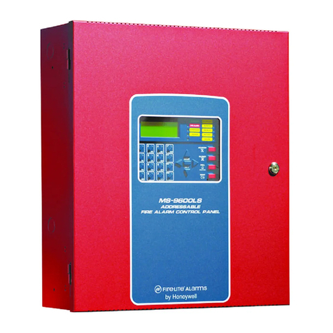
Honeywell Fire-Lite Alarms MS-9600LS User manual

Honeywell

Honeywell Fire-Lite Alarms MS-9600LS User manual

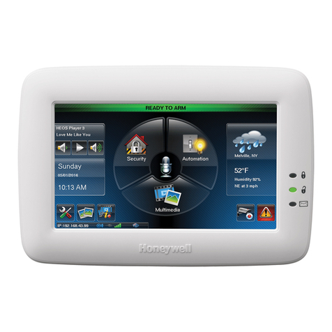
Honeywell Lynx Touch L5100 Installation guide

Honeywell

Honeywell Lynx Touch L5100 Installation guide

Honeywell LT-32 User manual

Honeywell

Honeywell LT-32 User manual

Honeywell Fire-Lite Alarms ES-200X User manual

Honeywell

Honeywell Fire-Lite Alarms ES-200X User manual

Honeywell nfs2-3030 Owner's manual

Honeywell

Honeywell nfs2-3030 Owner's manual

Honeywell HPZC10 Series User manual

Honeywell

Honeywell HPZC10 Series User manual

Honeywell Galaxy 2 Series User manual

Honeywell

Honeywell Galaxy 2 Series User manual

Honeywell Notifier ID50 Instruction sheet

Honeywell

Honeywell Notifier ID50 Instruction sheet

Honeywell Fire-Lite Alarms ES-200X User manual

Honeywell

Honeywell Fire-Lite Alarms ES-200X User manual

Honeywell NFS-3030 Installation and operating instructions

Honeywell

Honeywell NFS-3030 Installation and operating instructions

Honeywell Notifier AFP-3030 User manual

Honeywell

Honeywell Notifier AFP-3030 User manual

Honeywell MM3-MASTERTROL MM-3 Technical manual

Honeywell

Honeywell MM3-MASTERTROL MM-3 Technical manual

Honeywell NOTIFIER ID2000 Series Guide

Honeywell

Honeywell NOTIFIER ID2000 Series Guide

Honeywell Galaxy Flex User manual

Honeywell

Honeywell Galaxy Flex User manual

Honeywell SLC User manual

Honeywell

Honeywell SLC User manual

Honeywell ENVIRAZONE PANEL W8835 Operation manual

Honeywell

Honeywell ENVIRAZONE PANEL W8835 Operation manual

Honeywell Galaxy 16 User manual

Honeywell

Honeywell Galaxy 16 User manual

Honeywell Notifier AFP-100 User manual

Honeywell

Honeywell Notifier AFP-100 User manual

Honeywell Domonial cmi User manual

Honeywell

Honeywell Domonial cmi User manual

Honeywell MINI-ZONE 69-1361 Quick start guide

Honeywell

Honeywell MINI-ZONE 69-1361 Quick start guide

Honeywell Notifier NFS2-640 User manual

Honeywell

Honeywell Notifier NFS2-640 User manual

Honeywell IFP-2100ECS Technical specifications

Honeywell

Honeywell IFP-2100ECS Technical specifications

Honeywell AQUATROL AQ25142B Guide

Honeywell

Honeywell AQUATROL AQ25142B Guide

Popular Control Panel manuals by other brands

Siemens FC121-ZA quick start guide

Siemens

Siemens FC121-ZA quick start guide

Cofem LYON user manual

Cofem

Cofem LYON user manual

Twin-Star International DFS-220 quick guide

Twin-Star International

Twin-Star International DFS-220 quick guide

turck TX710HB-P3CV01 quick start guide

turck

turck TX710HB-P3CV01 quick start guide

Matrix Switch Corporation MSC-CP8X4E product manual

Matrix Switch Corporation

Matrix Switch Corporation MSC-CP8X4E product manual

WimTec OCEAN T6 Installation and operating instructions

WimTec

WimTec OCEAN T6 Installation and operating instructions

Exodraft EBC30 Installation and operation manual

Exodraft

Exodraft EBC30 Installation and operation manual

WIKA A2G-200 Operating	 instruction

WIKA

WIKA A2G-200 Operating instruction

Nordelettronica NE274 instruction manual

Nordelettronica

Nordelettronica NE274 instruction manual

Zeta Alarm Systems SMARTCONNECT SMART6 installation manual

Zeta Alarm Systems

Zeta Alarm Systems SMARTCONNECT SMART6 installation manual

Aprilaire Zoned Comfort Control 6203 Safety & installation instructions

Aprilaire

Aprilaire Zoned Comfort Control 6203 Safety & installation instructions

Tylo H1 Tonic manual

Tylo

Tylo H1 Tonic manual

Texecom Premier 24 Addendum manual

Texecom

Texecom Premier 24 Addendum manual

ESAB Aristo U82 instruction manual

ESAB

ESAB Aristo U82 instruction manual

UniPOS IFS7002 Service instructions for the staff

UniPOS

UniPOS IFS7002 Service instructions for the staff

Erreka VIVO-D102 Installer manual

Erreka

Erreka VIVO-D102 Installer manual

ZKTeco InBio Pro Series installation guide

ZKTeco

ZKTeco InBio Pro Series installation guide

LS XP40-TTA installation guide

LS

LS XP40-TTA installation guide

manuals.online logo
manuals.online logoBrands
  • About & Mission
  • Contact us
  • Privacy Policy
  • Terms and Conditions

Copyright 2025 Manuals.Online. All Rights Reserved.