Schlage KP212 Technical specifications

KP212 Keypad
Installation and Programming Instructions
23852890
www.schlage.com
(877) 671-7011
Specifications
Case Dimensions:
6¹⁄₂”L x 1³⁄₄”W x 1¹⁄₈”D
Electrical:
Voltage: 12-24VAC/DC
Current: 53mA@12VDC;
72mA@24VDC; 95mA@12VAC
108mA@24VAC
Relay Contacts:
Main Relay (controller): 2A
Bell Relay:
Form A; 1 Amp @ 30VAC/DC
Environmental:
-20° F to 130° F
For Indoor and Outdoor Use
Features
• 120 User Capacity
• Programmable Relay Time (0 to 99 seconds)
• Request to Exit (REX) Input
• Vandal Resistant Case
• Sealed for Indoor or Outdoor Applications
• LED’s for Relay Status Indication
• Bell Output
• Surface Mount
• Illuminated Hardened Keys
• Rated for Greater than One Million Key Cycles
Applications
• Low to Medium/Heavy Traffic Areas
• Rough Service Environments
• Mullion Frame Mounting
• Dimly Lit Areas
Description:
Schlage’s KP212 keypad combines elegant looks with a mullion
mount design in a rugged, vandal resistant case, which you can use
for almost any application. The KP212 has hardened backlit keys
designed to perform in medium to high traffic areas and in rough
duty environments. The electronics are also conformal coated, which
makes the keypad suitable for indoor or outdoor applications.
Basic Operation:
To gain access through the door enter your code (1-6 digits) followed
by the key on the keypad.
Packing List:
1) KP212 Keypad
(1) Eight-Conductor Wire Harness
(1) Mullion Hardware Pack
(1) ⁵⁄₆₄” Allen Wrench
(1) Anti-Oxidant Grease Pack
(1) Installation/Programming Manual
Wire Harness Configuration:
2
4
6
8
1
3
5
7
Pin Wire Color Signal Name
1 Red Power (+)
2 Black Power (-)
3 White/Black REX
4 White/Yellow Main Relay NC
5 Blue Main Relay Common
6 Brown Main Relay NO
7 White Bell Relay Contact (A)
8 White Bell Relay Contact (B)

2
Keypad Installation Procedure:
1. Drill through the back plate using a ¹¹⁄₆₄” bit. Use the template on the back page to accurately mark the mounting holes before
drilling. Then drill the mounting holes with a ⁹⁄₆₄” drill bit. Also drill the hole for the wires. This may vary depending on the number of
conductors required. Refer to mounting height below.
2. Wire the keypad using the diagrams in the following sections.
3. Mount the KP212 keypad onto the mounting surface using the provided screws. Do no over-tighten the screws, which may result in
damage.
Keypad Mounting Height
Mounting height can vary depending on requirements. An appropriate range is typically between 48 and 52 inches on center off the floor.
48 - 52”
Wiring an Electromagnetic Lock (Maglock)
1. Connect the red (V+) and black (V-) wires to your power supply.
2. Connect the blue wire (relay common) to positive on your power supply.
3. Connect the white/yellow wire (relay normally closed) to the positive connection on your maglock.
4. Connect negative connection on your maglock to the negative on the power supply.

3
Basic Access Control Using an Electric Door Strike
1. Connect the red (V+) and black (V-) wires to your power supply.
2. Connect the blue wire (relay common) to positive on your power supply.
3. Connect the brown wire (relay normally open) to the positive connection on your door strike.
4. Connect negative connection on your door strike to the negative on the power supply.
Shunting a Normally Closed Zone
1. Connect the red (V+) and black (V-) wires to your power supply.
2. Connect the blue wire (relay common) to the common connection on the alarm contacts.
3. Connect the brown wire (relay normally open) to the normally open connection on the alarm contacts.

4
Wiring a Request to Exit Device (REX)
The KP212 is equipped with a REX input. The normally open REX input triggers the main relay for the amount of time you programmed for the
master code. If the master code is set to toggle, the REX only triggers the relay for 5 seconds. There is no programming required for the REX
to operate.
1. Connect the red (V+) and black (V-) wires to your power supply.
2. Connect the common connection on the REX device to the negative on your power supply.
3. Connect the white/black wire to the normally open connection on the REX device.
Wiring the Bell Output to a Speaker:
The KP212 keypad has a built in bell button, which triggers a relay output when pressed. This relay is normally open and the contact closes
when triggered. You can use this relay output to trigger devices that require a momentary closure, such as a doorbell. The relay output
provides a dry contact, but you can run up to 30VAC/DC through it for devices that require power to operate. The diagram below shows these
connections.
White Wire
Speaker
White Wire
To Separate Power Supply
To Keypad
V+ V-

5
Programming the KP212 Keypad
To program the KP212 you first must enter program mode. To enter program mode enter the following on the keypad: 99 # program code
(default program code is 1234).
Keypad Default Settings
Option Default Setting Option Default Setting
Master Code 1234 Main Relay Time 5 Seconds
Audio Keypress Feedback Enabled Visual Keypress Feedback Enabled
Auto-Entry Disabled Door Bell Select Continuous
Keypad Illumination Enabled Keypad Dimming Enabled
Programming Options Chart
Command/Action Keys to Enter/Details
Change Master Code 1 # new code new code
Change Main Relay Time relay time # 1 # master code master code
Add/Change User user location # new code new code
Note: Users programmed with this command use master code relay time.
Add Toggle User 00 # user location # new code new code
Add User with Specific Relay Time relay time # user location # new code new code
Command 30
Set/Clear Keypad Options (options below,
defaults in bold)
30 # option # set/clear # **
Option Clear Set
0 – Audio Keypress Feedback 0 = Disabled 1 = Enabled
1 – Visual Keypress Feedback 0 = Disabled 1 = Enabled
2 – Auto-Entry 0 = Disabled 1 = Enabled
3 – Keypad Illumination 0 = Disabled 1 = Enabled
4 – Keypad Dimming 0 = Disabled (always bright) 1 = Enabled
5 – Door Bell Select 0 = Disabled 1 = Enabled
Command 32
Set Bell Output Time
32 # 0 # time # Set timed output (1 – 99 seconds)
32 # 0 # 0 # Set to continuous
Command 46
Reset Keypad to Default Settings 46 # 00000 # 00000 #
Exit Program Mode Press the Key
Notes:
1. The KP212 can store 120 user codes, including the master code. Codes can be from 1 to 6 digits long.
2. When auto-entry is enabled, users with codes the same length as the master code do not have to press the key after entering
their code to enter the door.
3. When keypad dimming is disabled the backlighting remains at full intensity (does not dim).
4. When the door bell output is set to continuous the relay is energized as long the door button is pressed. When you release the
button the relay de-energizes.

6
Programming Examples
Changing the Master Code:
The following example show how to change the master code to 4875 from the default of 1234.
1. Enter Program Mode 99 # 1234 *
2. Program New Master Code 1 # 4875 * 4875 *
3. Exit Program Mode *
Change the Main Relay Time
The following example shows how to change the main relay time. The master code is 4875.
1. Enter Program Mode 99 # 4875 *
2. Change the Main Relay Time 10 # 1 # 4875 * 4875 *
3. Exit Program Mode *
Adding User Codes:
The following example shows how to program user 2 with a code of 1749 and user 3 with 9328. The master code is 4875.
1. Enter Program Mode 99 # 4875
2. Program User # 2 2 # 1749 * code *
3. Program User # 3 3 # 9328 * code *
4. Exit Program Mode *
Programming a Toggle User
The following example shows how to program user 4 as a toggle user with a code of 98773. The master code is 4875.
1. Enter Program Mode 99 # 4875 *
2. Change the Main Relay Time 00 # 4 # 98773 * 98773 *
3. Exit Program Mode *
LED Indications
LED State Description
Red Solid Door Locked
Green Solid Door Unlocked
Yellow Solid Programming Error
Yellow Flashing Slowly Program Mode
Yellow Momentary Flash Visual Keypress Feedback

7
Troubleshooting
Issue Explanation Solution
LED’s cycling slowly from right to left. The KP212 Mullion is designed to monitor for
low voltage. Once low voltage is detected, the
keypad turns off the backlighting to ensure
operation of the keypad until the problem can
be attended to.
Verify the power supply output voltage. If it is
below the voltage threshold of 7.5 Volts AC or
9 Volts DC, you must increase the voltage to
between 12-24 Volts.
LED’s cycling rapidly from left to right and the
keypad has lost all operation.
The KP212 Mullion is designed to monitor for
over voltage. This is a very “severe” condition
and significantly affects the keypad’s
operation. Once the over voltage is detected,
the keypad shuts down all operation and
does not operate until the voltage is lowered.
Verify the power supply output voltage. If it
is over the voltage threshold of 35 Volts, you
must lower the voltage below 29 Volts.
Can’t access programming mode using the
master code.
The code you are entering is likely not the
master code.
Perform the program mode loopback in the
following section to enter program mode and
reprogram the master code.
No LED’s are lit on the keypad. Power is not reaching the keypad. First verify there is voltage at the keypad.
If not, verify there is voltage at the power
supply. If there is voltage, verify continuity
on the wires out to the keypad. Otherwise
contact the power supply manufacturer or IEI,
if there is a problem with the keypad.You also
may try power the keypad with a 12V battery
to verify operation.
DEALERS/INSTALLERS ONLY! End users must contact the dealer/installer for support. If the keypad still does not work after troubleshooting,
please call IEI’s techinal support department at 1-800-343-9502 (outside MA) or 1-800-733-9502 (inside MA).
Testing the Keypad
After installing the keypad, IEI recommends that you perform the keypad self-test once a year, to ensure that the keypad is working properly.
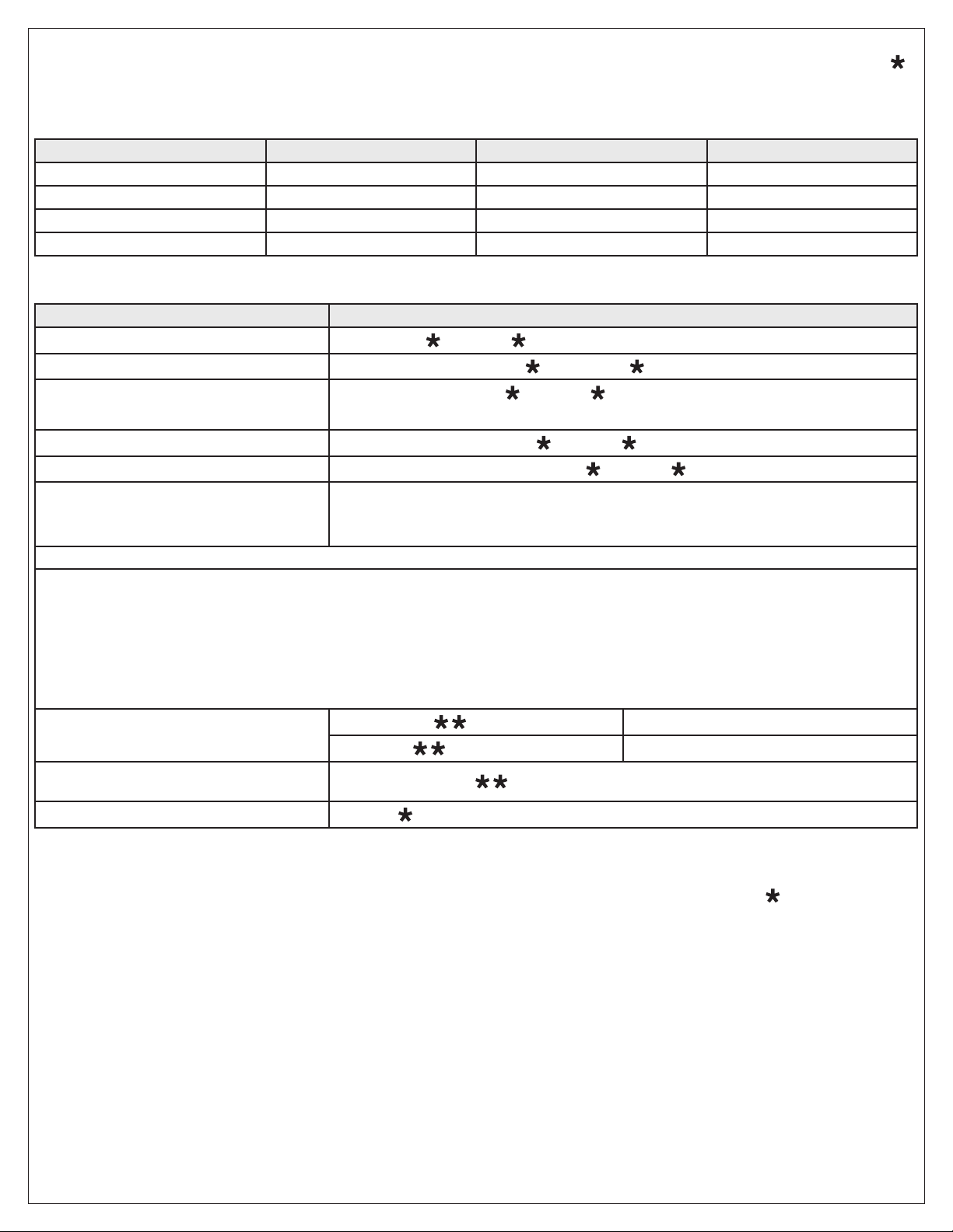
• To perform the self-test, with the unit powered up, press the following keys on the keypad: 7890#123456*
• If all 12 key presses are accepted, the keypad enters self-test mode.
• The LEDs alternate three times followed by the sounder beeping three times.
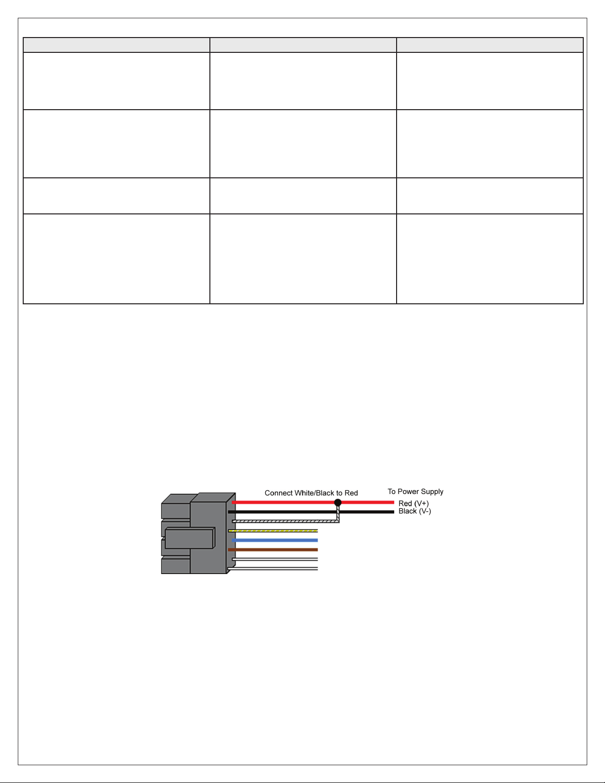
Program Mode Loopback
If you’ve forgotten the master code use the following loopback connection to enter program mode. Power down the unit, short the white/black
wire to the red wire, then power the unit back up. The yellow LED should be flashing. Now change your master code or reset the unit. Power
the keypad down and reconnected the wire harness in the original configuration.
Warranty
International Electronics Inc. (IEI) warrants its products to be free from defects in material and workmanship when they have been installed in accordance with
the manufacturer’s instructions and have not been modified or tampered with. IEI does not assume any responsibility for damage or injury to person or property
due to improper care, storage, handling, abuse, misuse, normal wear and tear, or an act of God.
IEI’s sole responsibility is limited to the repair (at IEI’s option) or the replacement of the defective product or part when sent to IEI’s facility (freight and insurance
charges prepaid) after obtaining IEI’s Return Material Authorization. IEI will not be liable to the purchaser or any one else for incidental or consequential
damages arising from any defect in, or malfunction of, its products.
Except as stated above, IEI makes no warranties, either expressed or implied, as to any matter whatsoever, including, and without limitation to, the condition of
its products, their merchantability, or fitness for any particular purpose.

©2011 Schlage Lock Company
Printed in U.S.A.
23852890 Rev. 04/11-a
Keypad Mounting Template
Mounting Holes: ¹¹⁄₆₄”
Wiring Hole: ⁷⁄₈”
3²⁵⁄₆₄ (3.393)”
1⁷⁄₁₆ (1.433)”
The Schlage keypad is desingd for
surface mount applications.You must
drill a ⁷⁄₈” hole for the wire harness
connector, as shown, so the unit is
flat against the mounting surface.
Table of contents
Other Schlage Keypad manuals