Schlage KC9354 User manual

KING COBRA/KING COBRA-2
NARROW STILE SERIES
57049-A 04-2007
KC9354/KC9354-2
Keypad Programmable
and SNAP Compatible Trim
For Narrow Stile Doors
KC9354/KC9354-2 INSTALLATION INSTRUCTIONS
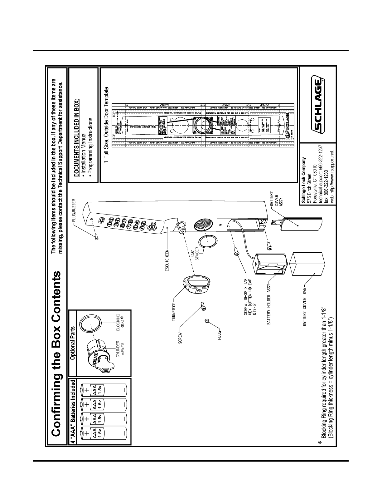
Contents of the Box
57049-A Page 2 04-2007
KC9354/KC9354-2 INSTALLATION INSTRUCTIONS
Contents of the BoxContent s of the Bo x

KC9354/KC9354-2 INSTALLATION INSTRUCTIONS
Introduction / Tools and Materials Needed / Contact Info
57049-A Page 3 04-2007
Introduction / Tools and Materials Needed / Contact Info
Introduction:
The KC9354/KC9354-2 will allow access by allowing the trim to unlock the exit
device when an access code or iButton is entered and the turnpiece is turned coun-
terclockwise. Mechanical key override is standard. The trim is compatible with the
dogging features available with the Adams Rite® exit devices.
The KC9354/KC9354-2 is compatible with Adams Rite®8600 concealed ver-
tical rod exit devices and 4780 Series 2-point deadlatches w/paddle on alumi-
num doors.
Tools and Materials Needed:
Contact Information:
Schlage Lock Company
575 Birch Street
Forestville, CT 06010
technical support: 866-322-1237
fax: 866-322-1233
web: http://www.irsupport.net
1
.F
l
at
h
ea
d
screw
d
r
i
ver w
/
stra
i
g
h
t,
1/8”
w
id
e
bl
a
d
e
2. Small Philips head screwdriver
3. 1/16” Allen wrench
4. Long nose needle-nose pliers
5. Center punch
6. Hammer
7. Power drill
8. 19/32” drill bit
9. 1/4” drill bit
10. Jig saw w/blade
11. Drill & Tap for 10-32 threads

KC9354/KC9354-2 INSTALLATION INSTRUCTIONS
Door Preparation
57049-A Page 4 04-2007
Door Prepar ation
Door Conditions:
Installation may require the use of a cover plate (a) to cover the holes left in the door.
If an existing pull (b) must be removed, Ives offers a compatible pull.
>Schlage Cover Plate P/N: KC9000-KRP
>Ives Pull P/N: 8190-18-xxx (xxx = finish)
For factory prepped doors, use dimensions
shown. Dimensions are referenced from cen-
ter of 1-1/4” cylinder hole. Backset is deter-
mined by the Adams Rite® lock.
When installing new Adams Rite® locks,
do not install outside cylinder (because this
trim replaces it).
(3.957”)
(2.693”)
Backset is determined by
the Adams Rite® lock.
(6.656”)
b
a
Horizontal centerline for
Adams Rite® 8600 Rim
KC9354/KC9354-2 INSTALLATION INSTRUCTIONS
Cams, Cores, Cylinders and Blocking Rings
57049-A Page 5 04-2007
Cams, Cores, Cylinders and Blocking Rings
Cams For Mechanical Override Cylinder:
IC Cores:
Cylinders / Blocking Rings:
T
h
e K
C9000
tr
i
m requ
i
res t
h
e use o
f
a c
l
over
l
ea
f
cam
(
a
)
. T
hi
s
is a list of compatible Schlage parts. For other manufacturers,
consult cross-reference charts.
> Cam for Standard Mortise cylinder: Schlage Everest: L583-153
Schlage Classic: L583-254
> Cam for Interchangeable Core: Schlage IC Cam: L583-255
a
>
S
ma
ll
Format I
C
core w
/
cam:
S
c
hl
age:
80
-
108
-<FINI
S
H>
NOTE: This core requires the use of 1/4” blocking ring:
Schlage: 36-079-025-<FINISH>
> Fu
ll
Si
ze I
C
core w
/
cam:
S
c
hl
age:
30
-
016
-<FINI
S
H>
NOTE: This core requires the use of 3/8” blocking ring:
Schlage: 36-079-037-<FINISH>
T
h
e K
C9000
can use a
1
-
1/8”
mort
i
se cy
li
n
d
er w
i
t
h
out t
h
e use
of a blocking ring. For cylinders longer than 1-1/8” a blocking
ring is required. The blocking ring thickness is equal to the cyl-
inder length, minus 1-1/8”. For example, if you use a 1-1/2” cyl-
inder you need a 3/8” blocking ring. Compression rings can be
ordered from a Schlage distributor:
Thickness: Schlage Part Number:
N
o compression ring: 1/8” 36-079-012-<FINISH>
1/4” 36-079-025-<FINISH>
3/8” 36-079-037-<FINISH>
1/2” 36-079-050-<FINISH>
KC9354/KC9354-2 INSTALLATION INSTRUCTIONS
Installing the KC9354/KC9354-2
57049-A Page 6 04-2007
Installing the KC9354/KC9354-2
Installing the KC9354/KC9354-2
If your trim has a key cylinder already installed, skip to Determine Hand: on page 12. Other-
wise, continue with Loosen the Baseplate Screws: on this page.
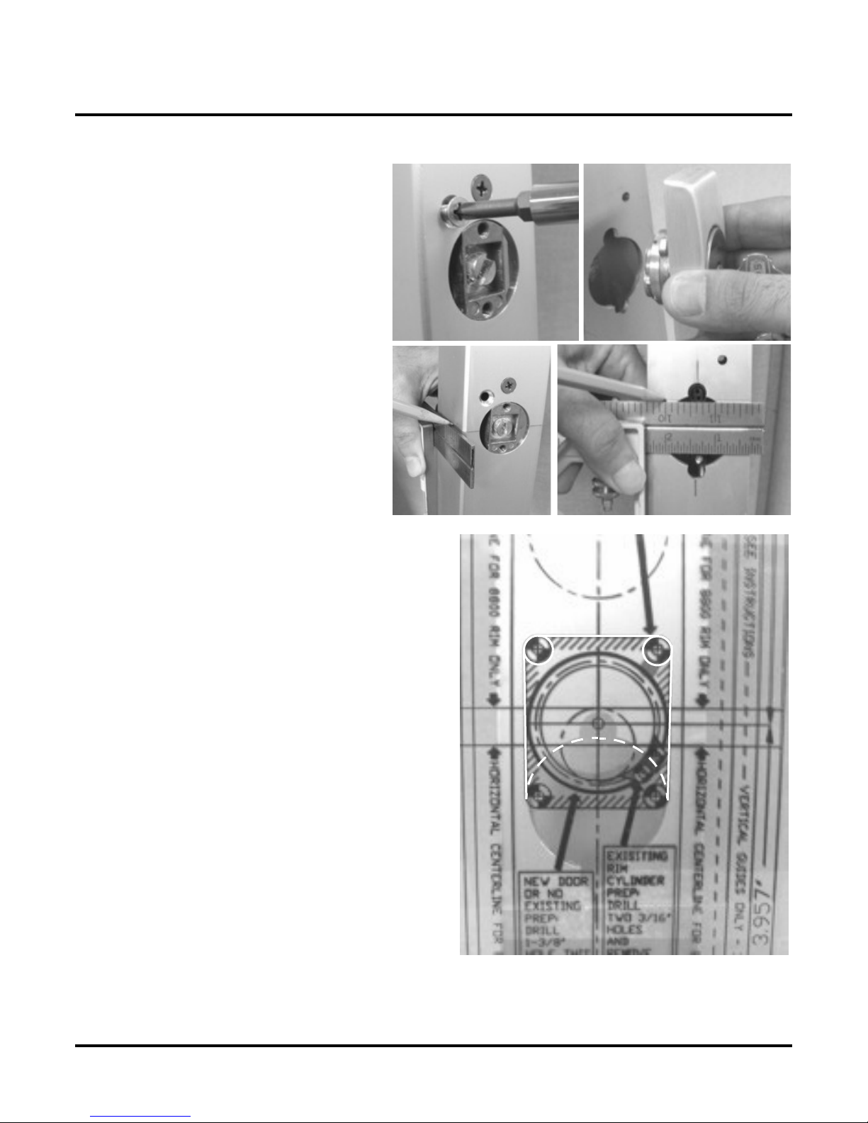
1) Loosen the Baseplate Screws:
2) A Key Cylinder That Is At Least 1-1/8” Long Must Be Installed:
IMP
O
RT
A
NT: Do not remove any o
f
t
h
e screws
i
n t
h
e
f
o
l
-
lowing step or it will be difficult to reinstall them.
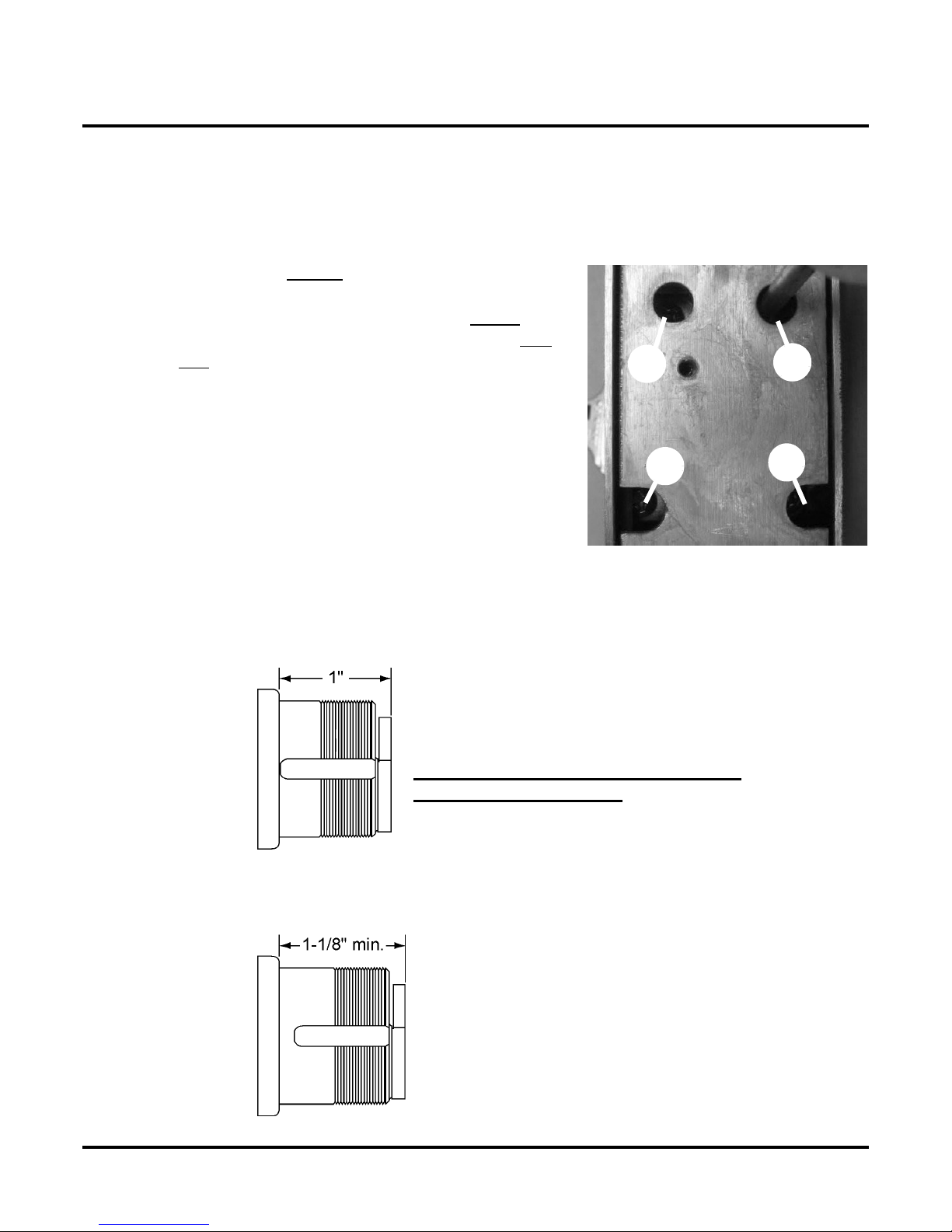
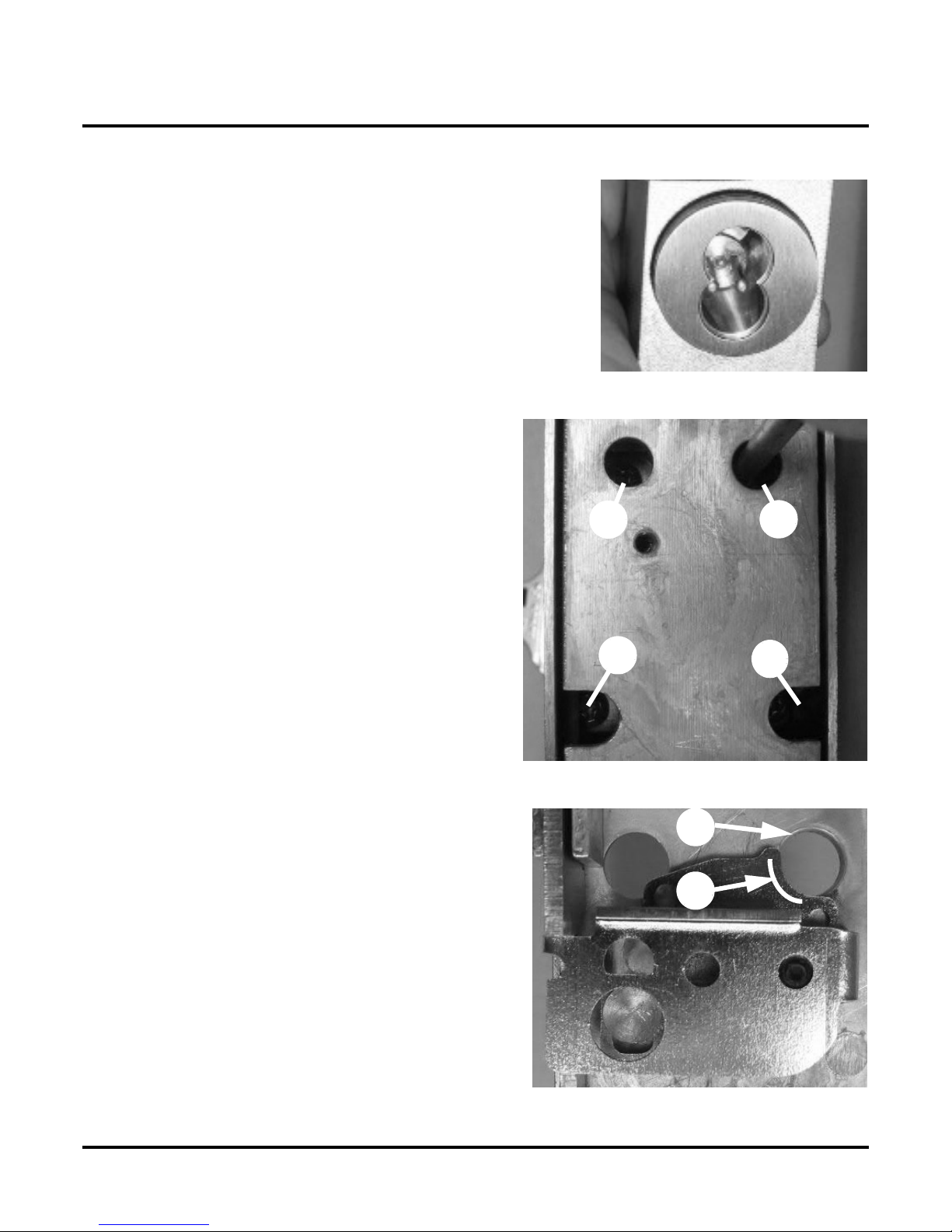
• Using a small Philips head screwdriver, loosen screws
a& bin baseplate, around key cylinder hole, one
turn.
NOTE: Screws a, b, c & d are set at the factory.
Screws a & b are tightened and screws c & d are left loose.
b
d
a
c
> T
h
e
k
ey cy
li
n
d
er t
h
at you
i
nsta
ll
must
b
e
1
-
1/8”
l
ong or
l
onger.
>>>> Do not attempt to install a key cylinder that is shorter than 1-1/8”
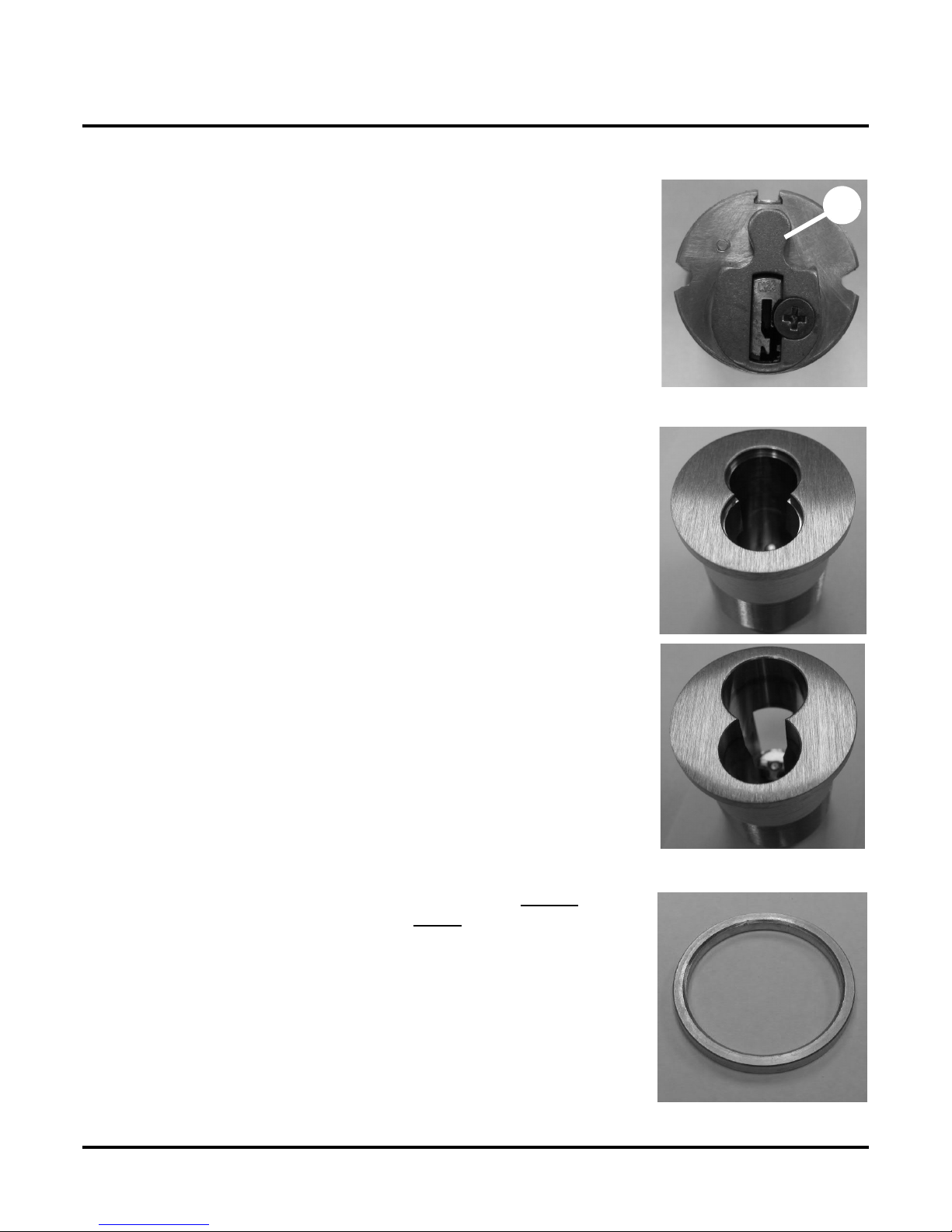
> The two photos below illustrate the difference between a 1” and a 1-1/8” key cylinder.
1” long key cylinder.
DO NOT ATTEMPT TO INSTALL A 1”
LONG KEY CYLINDER.
1-1/8” long key cylinder
ONLY INSTALL A KEY CYLIN-
DER THAT IS AT LEAST 1-1/8”
KC9354/KC9354-2 INSTALLATION INSTRUCTIONS
Installing the KC9354/KC9354-2
57049-A Page 7 04-2007
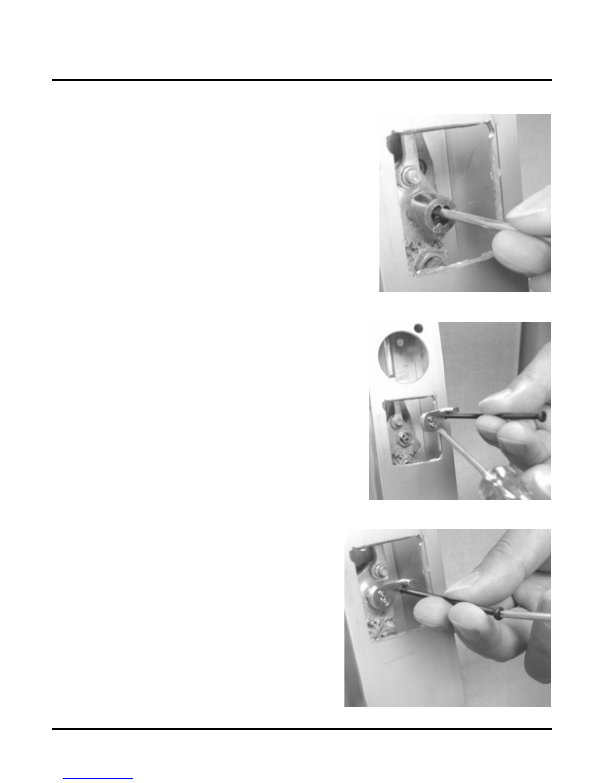
3) Make Room for Key Cylinder:
4) Hold Dead Latch in Place:
5) Verify Placement of Dead Latch:
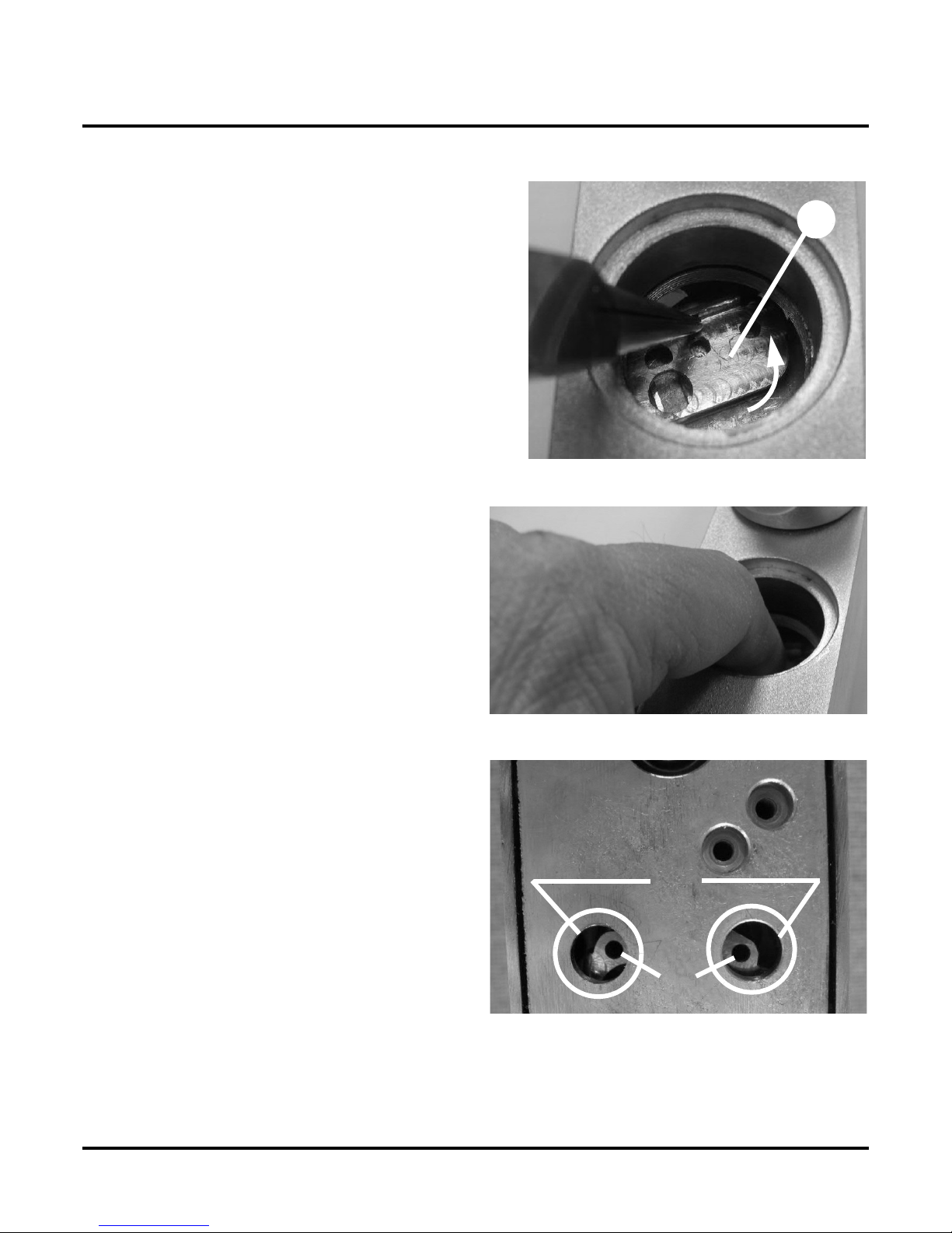
Due to the d
i
ameter o
f
the key cyl
i
nder,
i
t
i
s necessary
to have dead latch (a) placed out of the way when
installing the key cylinder. Therefore...
• Using your finger or a pair of needle-nose
pliers, push dead latch towards the top end
of trim as indicated by arrow in photo.
NOTE: As indicated by arrow in photo, you’ll notice
that when you push the dead latch forward, it will
swing a little bit in a counterclockwise direction.
a
T
o
i
nsure that dead latch
i
s placed
f
ar enough out
o
f the way to allow key cylinder to be threaded in
p
roperly:
• Insert a finger into key cylinder hole and
hold dead latch firmly in place.
• Carefully turn the trim over while keep-
ing the dead latch in position.
Two holes on dead latch (a) should be showing
within the two holes (b) in baseplate.
Fig. 1
a
b

KC9354/KC9354-2 INSTALLATION INSTRUCTIONS
Installing the KC9354/KC9354-2
57049-A Page 8 04-2007
6) Install the Key Cylinder:
Table 1: Blocking Rings
Table 2: Recommended Cams
7) Align Key Cylinder:
Key Cylinder Length Blocking Ring (Schlage P/N; XXX = finish)
• 1-1/4” 1/8” (36-079-012-XXX)
• 1-3/8” 1/4” (36-079-025-XXX)
• 1-1/2” 3/8” (36-079-037-XXX)
• 1-5/8” 1/2” (36-079-050-XXX)
Cylinder/Core Schlage Type Part Number
• Standard Mortise Cyl Everest L583-153
• Standard Mortise Cyl Classic L583-254
• Interchangeable Core IC Cam L583-255
• Insta
ll
.
0
5
0”
cy
li
n
d
er was
h
er.
IMPORTANT: A .050” cylinder washer must be used IN ALL CASES,
regardless of the key cylinder length.
• If you are installing a cylinder that is longer than 1-1/8”, you
must also install a blocking ring (see Table 1: Blocking
Rings, on page 8).
A simple formula for determining blocking ring thickness is:
Blocking ring thickness = length of cylinder minus 1-1/8”
• If not already done, install cam onto cylinder. Cam must be clo-
ver leaf design (see Table 2: Recommended Cams, on page 8).
• Tilt top of trim down at a sharp angle.
• Screw in key cylinder until it stops. Use mechanical key as a han-
dle for turning if necessary.
•
Af
ter screw
i
ng
i
t a
ll
t
h
e way
i
n,
b
ac
k
o
ff
on
k
ey cy
li
n
d
er
(no more than one turn) until key is at the bottom. If key
cylinder has a logo (a), logo should be at the top of key
cylinder. a
KC9354/KC9354-2 INSTALLATION INSTRUCTIONS
Installing the KC9354/KC9354-2
57049-A Page 9 04-2007
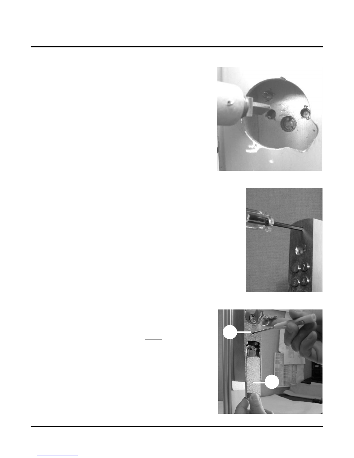
8) Alignment of Interchangeable Cores:
9) Tighten the Four Screws in the Baseplate:
10) The Dead Latch’s “Critical Edge:”
• I
f
an I
C
C
ore
i
s use
d
, center t
h
e
i
nter
f
ace towar
d
t
h
e
bottom.
• T
i
g
h
ten t
h
e
f
our
b
asep
l
ate screws
i
n t
h
e
f
o
l
-
lowing order:
> Tighten aand buntil snug.
> Tighten c and duntil snug.
> Fully tighten aand b.
> Fully tighten cand d.
> Check all four screws to make sure that
all four are completely tight.
b
c
a
d
• For c
l
ar
i
ty purposes on
l
y, p
h
oto on t
h
e r
i
g
h
t
i
s
a view of deadlatch with escutcheon removed.
• Edge (a) is referred to as the dead latch’s
“critical edge.”
IMPORTANT: In the next step, the “critical edge” on
deadlatch will have to be lined up with hole (b) in
baseplate. See Position the Dead Latch’s Set Screw
Hole: on page 10
a
b
KC9354/KC9354-2 INSTALLATION INSTRUCTIONS
Installing the KC9354/KC9354-2
57049-A Page 10 04-2007
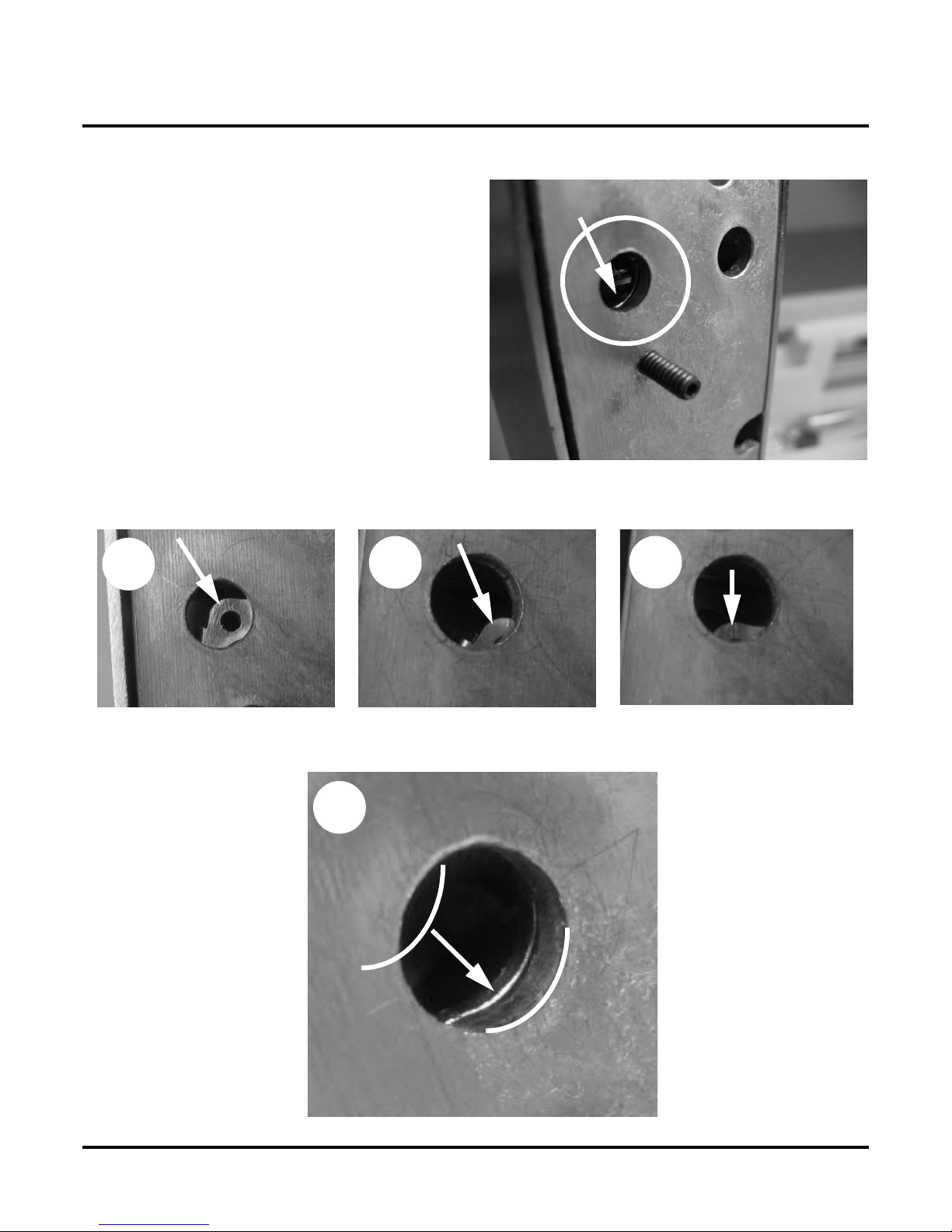
11) Position the Dead Latch’s Set Screw Hole:
• T
il
t t
h
e tr
i
m unt
il
you see t
h
e
“
cr
i
t
i
ca
l
edge” align with the larger hole in the
baseplate as shown in photo on right.
Look closely at edge of dead latch’s
“critical edge” (a) when doing this.
IMPORTANT: When the dead latch’s “critical
edge” is correctly aligned, the dead latch’s set
screw hole will likewise be correctly aligned.
Photos A, B and C below illustrate examples of an
incorrectly aligned critical edge. Photo D is an exam-
p
le of a correctly aligned critical edge.
a
NOT CORRECTLY
ALIGNED
NOT CORRECTLY
ALIGNED
NOT CORRECTLY
ALIGNED
CORRECTLY ALIGNED
ABC
D
KC9354/KC9354-2 INSTALLATION INSTRUCTIONS
Installing the KC9354/KC9354-2
57049-A Page 11 04-2007
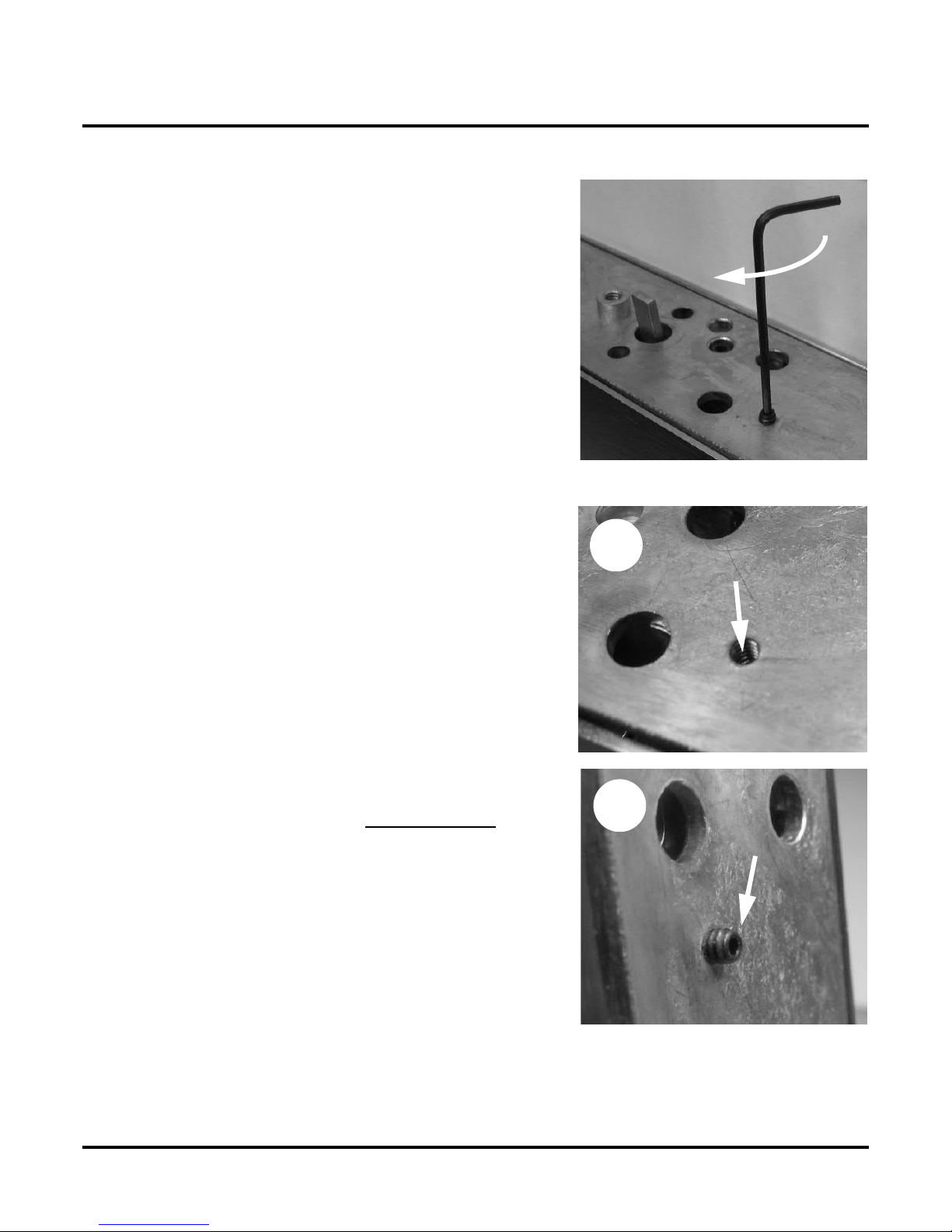
12) Partially Tighten the Set Screw:
13) Fully Tighten the Set Screw:
• Us
i
ng a
1/16”
All
en wrenc
h
, part
i
a
ll
y turn
i
n t
h
e set
screw until outer end of set screw is about flush with
surface of baseplate.
• F
i
n
i
s
h
turn
i
ng
i
n t
h
e set screw unt
il
i
t
hi
ts t
h
e stop.
IMPORTANT: At this time, outer end of set screw should be
a little bit below the surface of the baseplate, as shown in
photo A. If you have turned in set screw as far as it will go
and it is protruding beyond the surface of baseplate, as
shown in photo B, the most probable cause is that dead
latch was not positioned properly (see Position the Dead
Latch’s Set Screw Hole: on page 10).
If you have turned the set screw in as far as it will go and it is
p
rotruding from the surface of the baseplate, do the following:
• Turn set screw back out so that about 1/4” is protrud-
ing from surface of baseplate.
• Reposition critical edge on dead latch according to
the instructions on page 10).
• Turn set screw in until it just hits the stop.
IMPORTANT: Do not overtighten set screw because the
baseplate may start to bow outward resulting in a gap
between trim and door when trim is mounted.
CORRECT
INCORRECT
A
B
KC9354/KC9354-2 INSTALLATION INSTRUCTIONS
Installing the KC9354/KC9354-2
57049-A Page 12 04-2007
14) Prep for Exit Only or New Installation:
• Prep
d
oor
f
or
d
ev
i
ce accor
di
ng to t
h
e
Ad
ams
Rite® instructions.
• Transfer horizontal and vertical centerlines
to front of door.
• Place the transparent self-adhesive template
on the door with the horizontal and vertical
centerlines lined upas shown. It is very
important to make the vertical guide lines
on the template parallel with the edge of the
door. The template can be lifted and reposi-
tioned as often as required to get the posi-
tion correct.
• Drill 1-3/8” hole thru the front of the door.
• Do not damage exit device parts inside the
door.
• Drill and tap the three #10-32 holes.
NOTE: If blind nuts are used (optional), see blind
nut installation instructions for correct hole size
and mounting method.
KC9354/KC9354-2 INSTALLATION INSTRUCTIONS
Installing the KC9354/KC9354-2
57049-A Page 13 04-2007
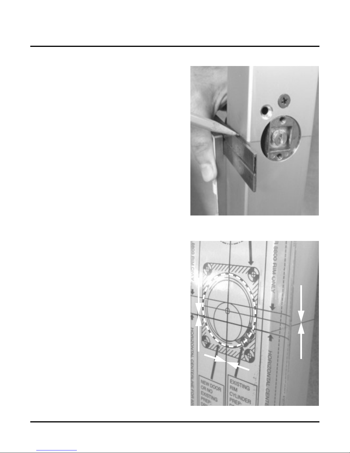
15) Prep with Existing Cylinder Escutcheon:
• Remove screw t
h
at secures t
h
e
cylinder escutcheon.
• Remove cylinder escutcheon.
NOTE: It will be necessary to remove
the exit device pushpad or paddle in
order to access the cylinder escutcheon
mounting screw. It will not be necessary
to remove the vertical rod(s). Refer to
Adams Rite® instructions for more
information.
• Locate and transfer device hori-
zontal and vertical centerlines
from inside to outside of door.
• Apply self-adhesive template to door.
• Place transparent self-adhesive template as
shown. It is very important to align the
template with the centerlines that were
transfered and make the vertical guide
lines on the template parallel with the
edge of the door. The template can be
lifted and repositioned as often as required
to get the position correct.
NOTE: The lines on the edges of the template are
for vertical guidance only. Do not line them up
with the edge of the door.
• Align the 1-5/16” circle up with the exist-
ing cylinder hole.
• Drill and tap three #10-32 holes.
• Drill two 3/16” dia. holes shown (right)
• Remove material indicated.
NOTE: If blind nuts are used (optional), see blind
nut installation instructions for correct hole size
and mounting method.

KC9354/KC9354-2 INSTALLATION INSTRUCTIONS
Installing the KC9354/KC9354-2
57049-A Page 14 04-2007
Prep with Existing Adams Rite®Lever Trim:
• Remove ex
i
st
i
ng tr
i
m.
S
ee
Ad
ams R
i
re
®
i
nstruct
i
ons
for more information.
• Apply transparent self-adhesive template as shown.
• It is very important to line up the template with the
existing trim prep and make the vertical guide lines on
the template parallel with the edge of the door. The
template can be lifted and repositioned as often as
required to get the position correct.
• The lines on the edges of the template are for vertical
guidance only. Do not line them up with the edge of the
door.
• The template can be lifted and repositioned as often as
required to get the position correct.
• Drill four 1/4” dia. holes shown (right)
• Remove material indicated.
• Drill and tap three #10-32 holes.
• Note that the middle hole (a) may be too close to the
large trim prep hole to tap properly. This hole may be
omitted if necessary.
NOTE: If blind nuts are used (optional), see blind nut installa-
tion instructions for correct hole size and mounting method.
a

KC9354/KC9354-2 INSTALLATION INSTRUCTIONS
Installing the KC9354/KC9354-2
57049-A Page 15 04-2007
16) Install Adapter Housing:
17) Verify That Handing Screw is Installed As Shown:
18) Apply Trim Gasket:
• Us
i
ng t
h
e prov
id
e
d
#8
-
32
screw, install adapter housing.
NOTE: If the KC900-KRP cove plate is
used, the provided spacer (a) must be
used between the interface attachment
and the baseplate
a
• Turn t
h
e
k
ey
180
d
egrees
CC
W.
• Rotate turnpiece CW.
> Cam (a) on interface should rotate with
turnpiece.
a
• Pee
l
paper
b
ac
ki
ng
f
rom
exterior gasket.
• Carefully apply gasket to
trim’s baseplate.
KC9354/KC9354-2 INSTALLATION INSTRUCTIONS
Installing the KC9354/KC9354-2
57049-A Page 16 04-2007
19) Remove Trim Interface Tube
20) Install Device Interface Cam:
21) Remove Holding Screw:
• I
f
present, remove tr
i
m
i
nter
f
ace tu
b
e us
i
ng sma
ll
p
hil
-
lips screwdriver. Use care not to let it drop into the
hollow door stile.
TIP: To help prevent interface tube from dropping into the
door stile, hold a small piece of paper underneath trim inter-
face tube.
• Insert two
#2
-5
6
p
hilli
ps
filli
ster
h
ea
d
screws
i
nto
device interface cam.
• While holding the part by the long screw install it
onto the exit device being careful not to drop the
screws into the door stile.
NOTE: The camshould must be positioned to the right as
shown in the picture. (If the door is open and the vertical
rods remain in the open condition, the cam orientation will
be up and to the right - this is normal.)
• Remove t
h
e
h
o
ldi
ng screw.
NOTE: The screw will not be required unless you need
to take the cam off for any reason.
KC9354/KC9354-2 INSTALLATION INSTRUCTIONS
Installing the KC9354/KC9354-2
57049-A Page 17 04-2007
22) Place Trim On Door:
23) Partially Tighten Trim’s Top Screw
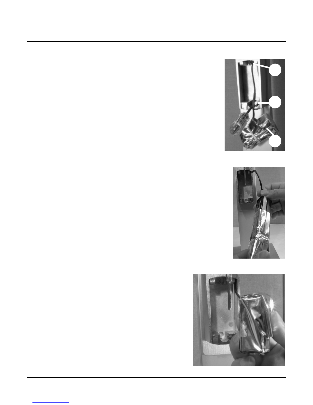
24) Remove Battery Cover:
•
Ali
gn tr
i
m w
i
t
h
ex
i
t
d
ev
i
ce
i
nter
f
ace. Repos
i
t
i
on ta
il
-
piece if necessary.
• Place trim on door.
• Us
i
ng a
b
a
ll
-en
d
,
1/8”
h
ex wrenc
h
, part
i
a
ll
y t
i
g
h
ten tr
i
m
’
s top
screw.
• I
f
not a
l
rea
d
y
d
one,
i
nsert
k
ey
i
nto cy
li
n
d
er an
d
turn
i
t
counterclockwise.
• Using a small, flat blade screwdriver, loosen the bat-
tery cover screw (a) ONLY TWO TURNS COUN-
TERCLOCKWISE.
• Slide off battery cover (b) from bottom.
• Pull out battery pack from battery compartment. Bat-
tery pack is attached to a wire harness.
IMPORTANT: Do not cut or attempt to remove the battery
pack’s wire harness.
a
b
KC9354/KC9354-2 INSTALLATION INSTRUCTIONS
Installing the KC9354/KC9354-2
57049-A Page 18 04-2007
25) Install Lower Mounting Screws:
26) Install Batteries:
27) Fold Battery Bag:
• Remove
b
attery pac
k
(
a
)
.
• Install and completely tighten both lower mounting screws (b) and
(c) located within battery compartment.
• Finish tightening top mounting screw.
b
c
a
• Remove an
d
reta
i
n
b
attery
b
ag.
IMPORTANT: DO NOT DISCARD BATTERY BAG. IT IS IMPORTANT
THAT IT IS REINSTALLED AFTER THE BATTERIES ARE INSTALLED
IN BATTERY HOLDER.
• Observe the polarity markings indicated on battery holder and install
four, AAA batteries accordingly.
• Slide battery bag onto battery holder.
• Fo
ld
b
attery
b
ag over.
IMPORTANT: The battery bag is used to protect the batteries
from moisture and to insulate them electrically from metallic
parts.

KC9354/KC9354-2 INSTALLATION INSTRUCTIONS
Installing the KC9354/KC9354-2
57049-A Page 19 04-2007
28) Install Battery Pack:
29) Install Battery Compartment Cover:
30) Install Water Plug.
• Insta
ll
b
attery pac
k
i
nto compartment w
i
t
h
b
ag open-
ing facing down.
• Tuck wiring neatly into compartment
•
Slid
e
b
attery compartment cover on
f
rom t
h
e
b
ottom.
IMPORTANT: Use caution not to pinch the battery wires.
• Tighten battery cover screw.
• Rotate key clockwise.
• Remove key.
• Insert water p
l
ug
(
a
)
i
nto top mount
i
ng screw
h
o
l
e.
• Using the end of a small Allen wrench or similar tool,
push plug into hole past surface.
INSTALLATION COMPLETE
a
KC9354/KC9354-2 INSTALLATION INSTRUCTIONS
Test Operation / Dimensions
57049-A Page 20 04-2007
Test Operation / D imensions
Test Operation
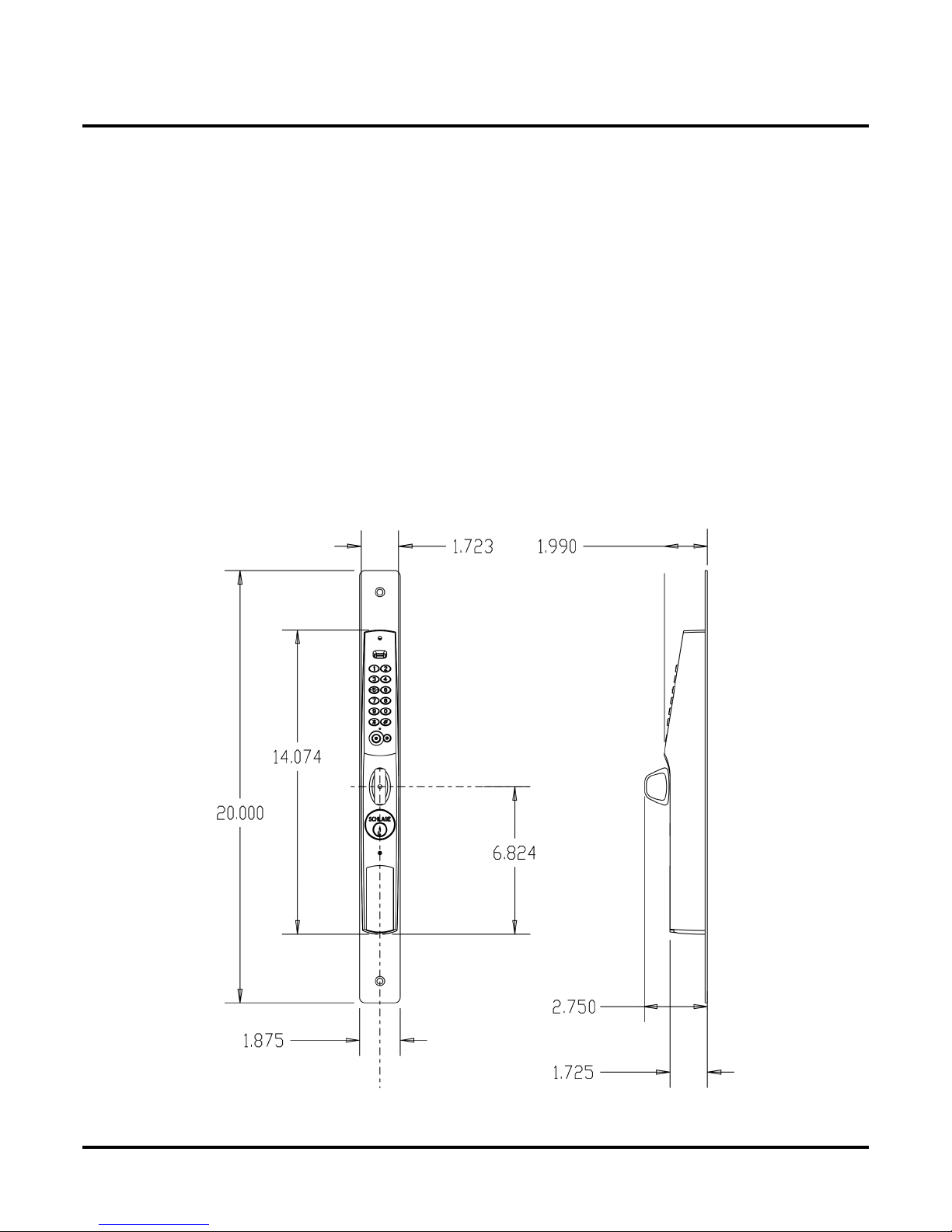
Dimensions
1
. Turnp
i
ece s
h
ou
ld
rotate
f
ree
l
y.
2. Insert key into cylinder and rotate counterclockwise 180 degrees.
3. Rotate turnpiece clockwise to unlock device
> Door should be able to be opened.
4. Let go of the turnpiece and close the door
> Door should be locked.
5. Remove key.
6. Using the keypad, enter the default access code: 1 3 5 7 9. The red LED should light each time a
button is pressed and when 9is pressed, the green LED should flash for five seconds during which
time the turnpiece should be engaged and door should be able to be opened again.
7. Test exit device to make sure it is operating properly. See to Adams Rite® instructions for more info.
SEE PROGRAMMING GUIDE FOR PROGRAMMING INFORMATION.
This manual suits for next models
3
Table of contents
Other Schlage Keypad manuals


Popular Keypad manuals by other brands

EVERSPRING
EVERSPRING SK201 instructions

Digital Monitoring Products
Digital Monitoring Products 9800 SERIES installation guide

AMX
AMX Metreau MET-13 datasheet

Russound
Russound A-K3 installation manual

Securitron
Securitron DK-16W Installation & operating instructions

Alarm Lock
Alarm Lock T3 Prox Cheat list


