23
W
DETAIL D-D
To Trim
(C)
To Exit
Device
(O)
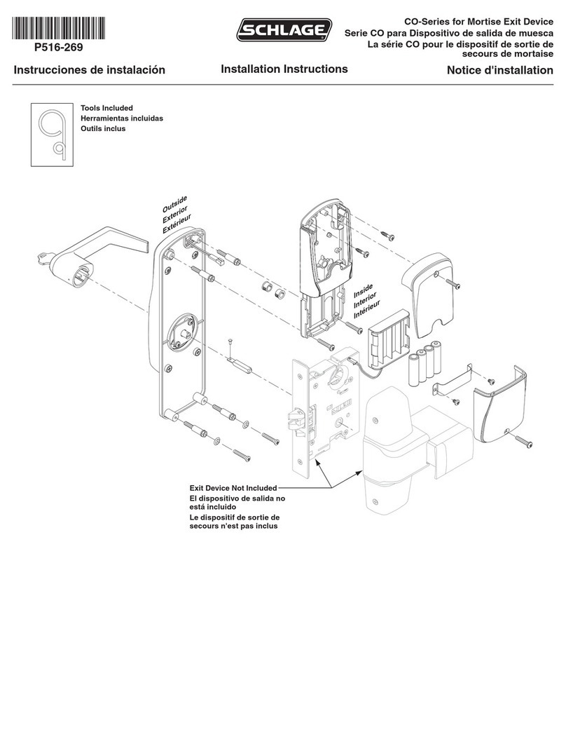
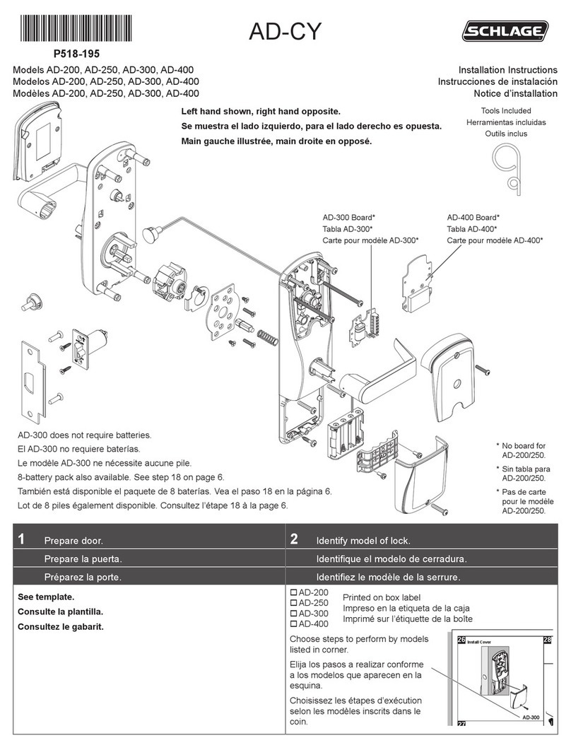
After door has been prepared, refer to illustration on right and
assemble lock components onto door in following order:
DETAIL D-B DETAIL D-A
LHR RHR
DETAIL D-C
V
Q
K
L
A
B
DF
H
G
T
R
S
S
O
J
M
R
Y
X
N
U
C
E
1 - Install Key Cylinder (A) (refer to DETAIL D-A):
- If A is longer than 1-1/8", insert B into C (refer to
BLOCKING RING TABLE on page 4).
- Insert A into C.
- Slide D over A.
- Using E, screw F onto A until tight.
- Line up nearest notch on F with tab on D.
- Bend tab on D into notch of F.
2 - If changing the Handing is necessary, refer to DETAIL
D-A and do the following:
- Using a 5/32" hex wrench, remove G.
- Remove H, rotate 180 degrees, slide back on shaft.
- Apply threadlocker to G, reinstall G.
3 - Preliminary Test of Trim (refer to DETAIL D-A):
- Insert key into A and turn CW (this engages A).
- Rotate H down.
RESULT: I must rotate as H is rotated.
4 - Install Stop Screw (J).
- With A engaged (see above), rotate H down & hold.
- Install J into proper hole (LHR or RHR).
RESULT: H should not rotate up from horiz. pos.
5 - Refer to DETAIL D-B and verify K is installed in L.
- If K is missing, install K (supplied).
6 - Place O on door, secure with T.
7 - Insert M into O (refer to DETAIL D-C & DETAIL D-D).
- DETAIL D-C:
> LHR - end with notches (N) towards C.
> RHR - end with notches (N) towards O.
- DETAIL D-D:
> Longest step (P) on M towards Q.
8 - Install Trim (C):
- Install R into C.
- Apply sticky side of S to C.
- Align M with I and place C on door.
- Install each T into each R.
- If they were removed, reinstall 2 screws (U).
9 - Observe polarity and install 4 batteries (V).
10 - Place W and X against C, secure with Y and Z.
INSTALLATION OF HARDWARE COMPLETE
See Page 4 for TESTING, TROUBLESHOOTING, and
OPERATIONAL TESTING - CM993 AND CL993.
I
R
LH HRR
"Night Latch" function
I
M
P
C
N
NSIDE
IOF
DOOR

