LaQ07 Framed - Mounting Instructions GB
2
© Schletter GmbH • Gewerbegebiet an der B15 • Alustraße 1 • 83527 Kirchdorf/Haag i. OB • Germany • Tel.: +49 8072 9191-200
Fax:
+49
8072
9191-9200
• E-mail:
[email protected] • www
.schletter
.eu
• Updated
08/2012
• Subject
to
change
without notice
Your contact in the UK: Schletter UK Limited, Tel.: +44 1296 461 800, Fax: +44 1296 461 801, E-mail: info@schletter.co.uk
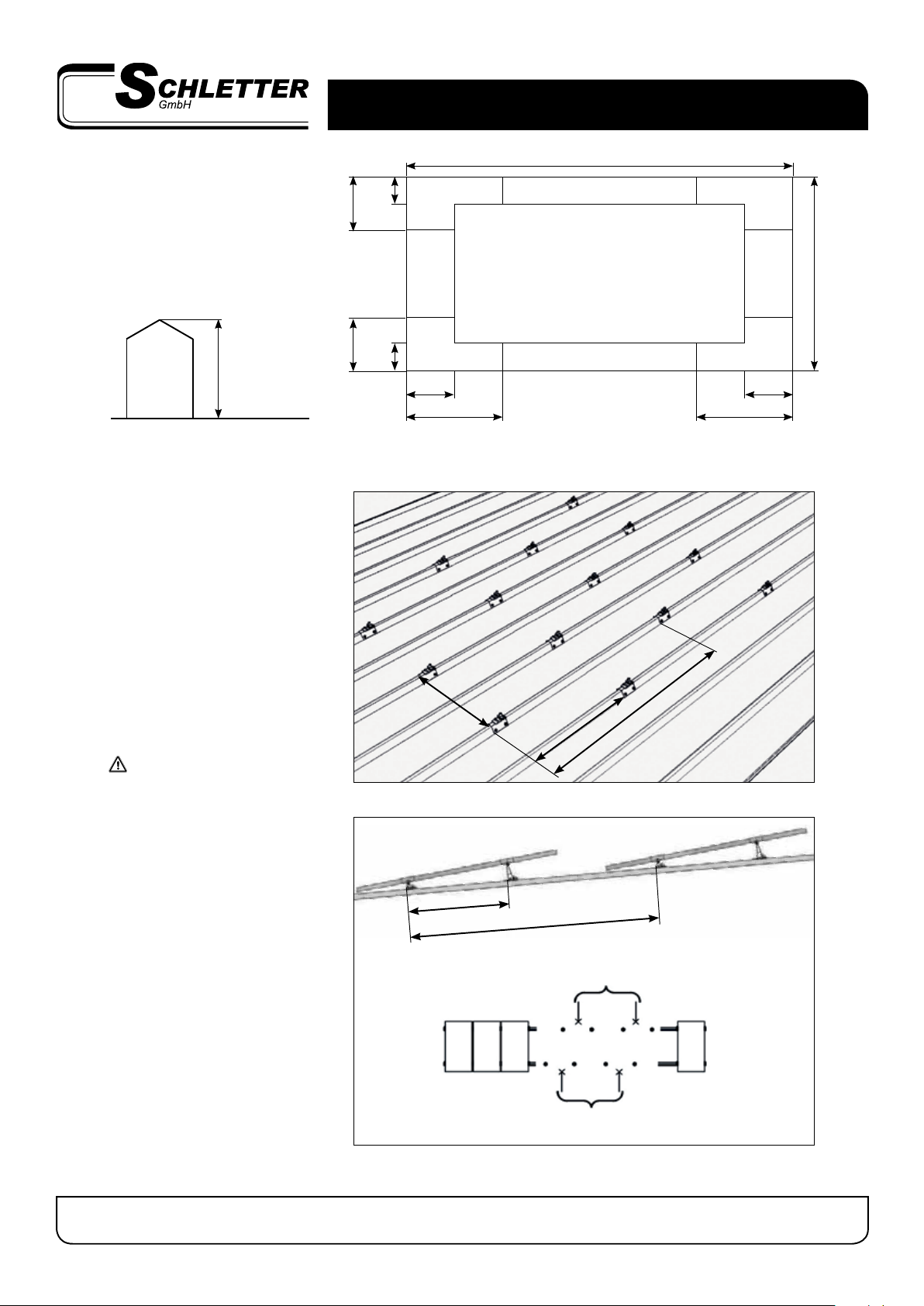
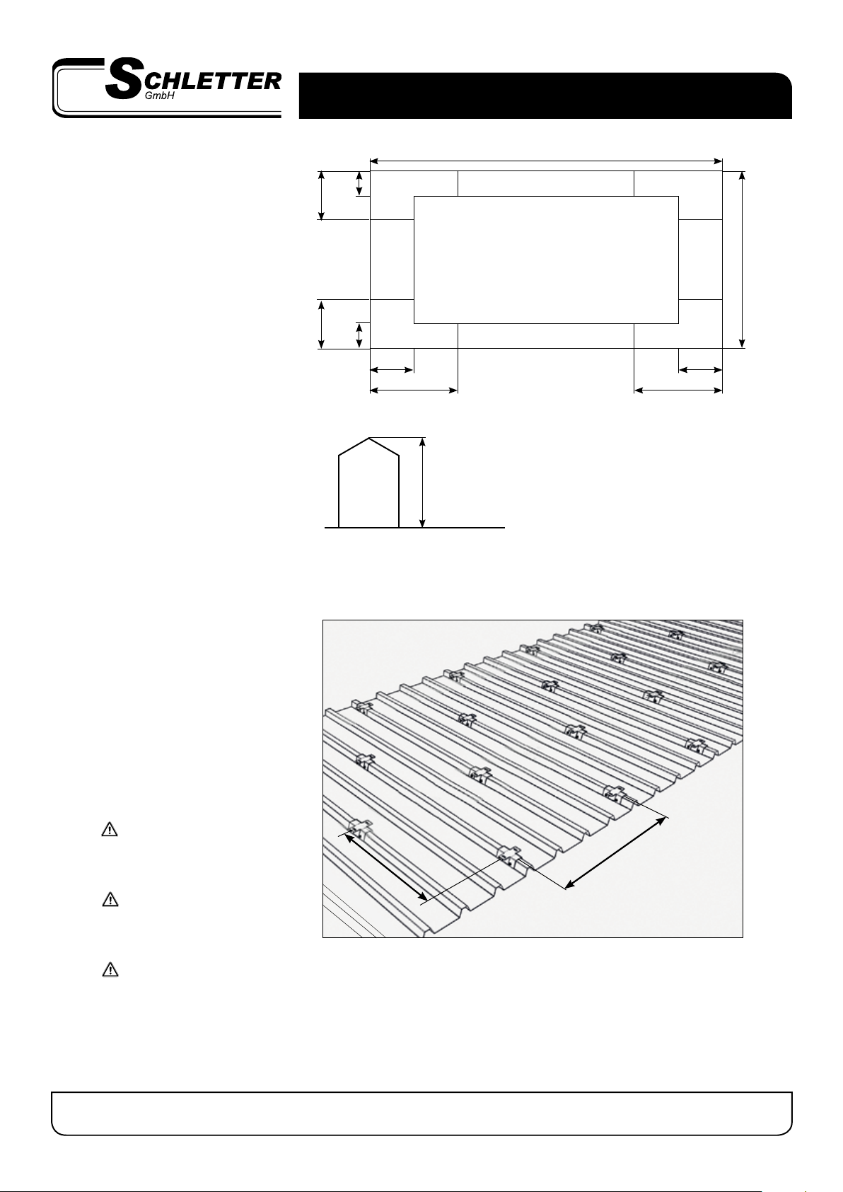
Mount fasteners
t Select corresponding distance a
between fasteners for the respective
module. Measurement ais derived
from the module width plus 20 mm.
t Distance between fasteners bshould
be taken from the structural analysis
for fasteners - schematic diagram is
displayed in Autokalkulator.
t Further recommendations are
offered in the structural analysis (for
fasteners).
The number of fasteners required is
also dependent upon the properties
of the roof - please verify details with
the manufacturer!
We recommend the use of a fas-
tener with a slotted hole (e.g. Fix2000
standard). Measurement acan there-
fore be optimally adjusted.
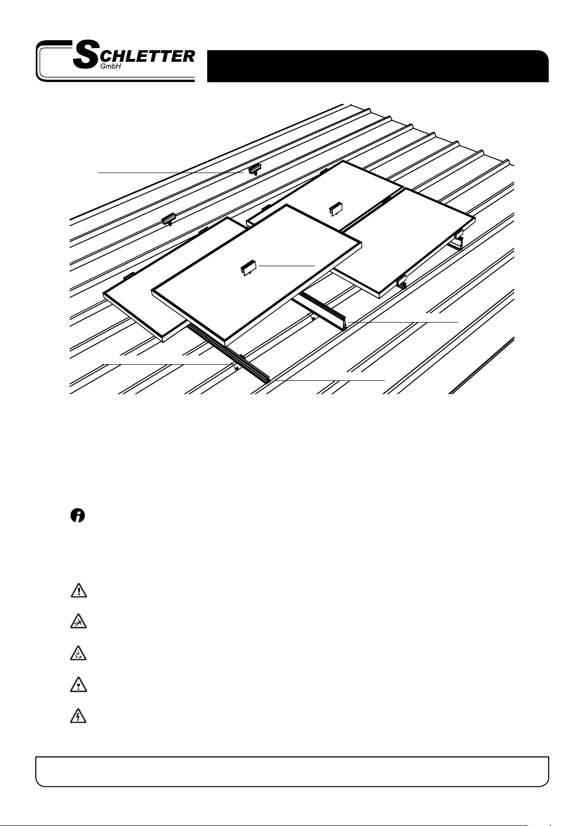
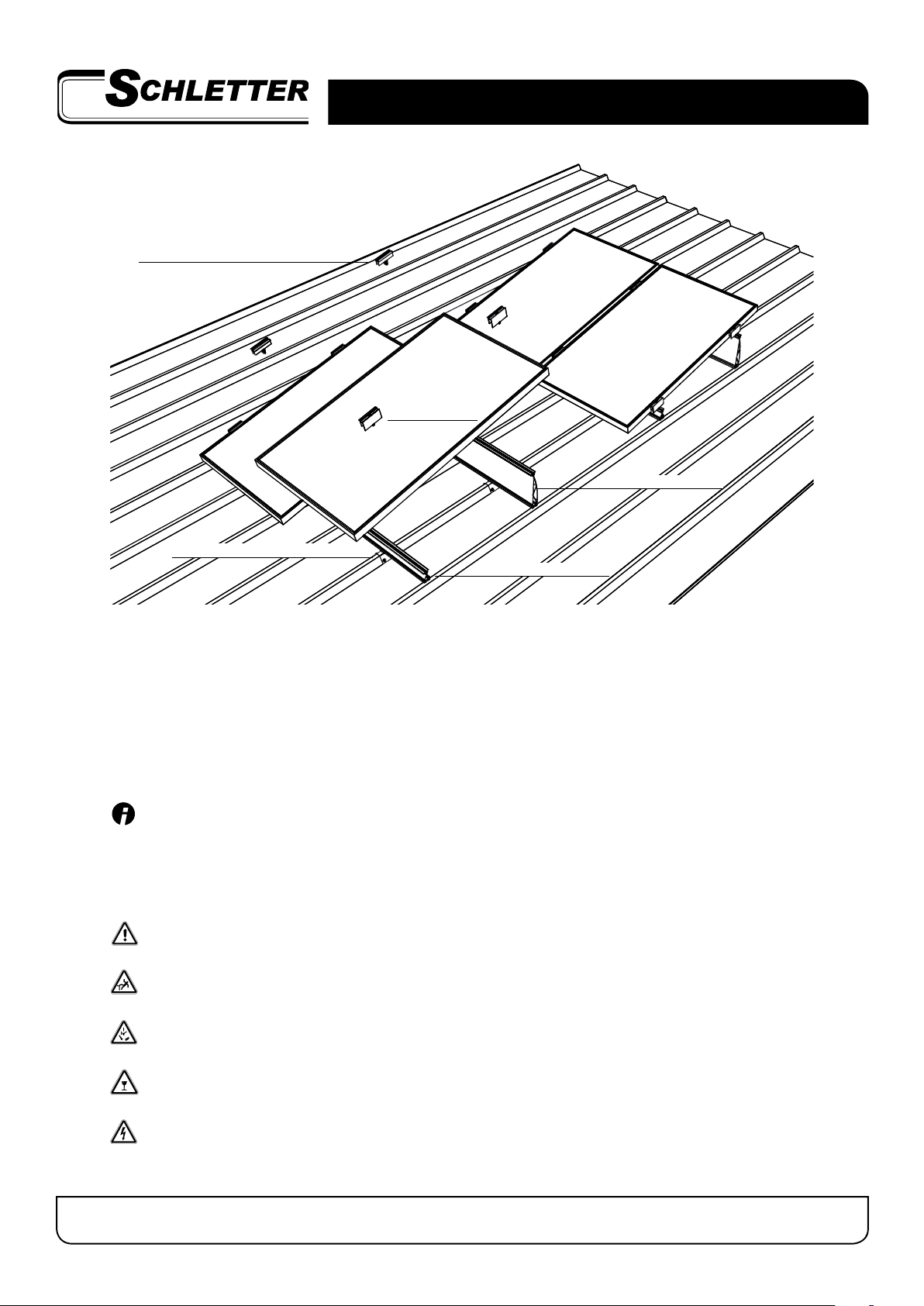
LAQ07 can be installed if the distanc-
es between module-bearing profiles
can be precisely set - e-g- trapezoidal
sheet metal roofs, seamed roofs and
cross rails.
a
Define the area of installation
t Concentrate the number of fasteners
in edge and corner zones.
t Further recommendations are oered
in the structural analysis.
Calculation formula:
e = min (x / y or 2 . h)
x
y
e/4e/4
e/10e/10
e/10
e/10
e/4
e/4
h
Building
b
Corner zone Edge zone Corner zone
Field zone
Edge
zone
Edge
zone
Corner zone Edge zone Corner zone