Schlosser KB55S User manual

Schlosser
Aufzugtechnologie GmbH
Felix-Wankel-Straße 4
85221 Dachau
T +49 8131 / 5186-0
www.schlosser.de
Ausgabe
edition
06.09.2018
Seiten
pages
1/7
Bearbeiter
person in charge
Kepplinger
Zeichnung Nr.
drawing nr.
5370.800.001
Safety Module lk
Progressive safety gear - upward/downward acting = payload + weight of lift car in FREE fall
Braking device = 1/2 payload + masses UPWARDS upon tripping the overspeed governor incl. UCM/A3
Tension shoe
Releasing bolt
Kingpin, can be pulled out
Spring steel strip, inside
Lockwash
Douple eccentric
Kingpin, can be pulled out
Brake shoe retainer
Release slider
Brake shoe
Brake pads
Brake shoe
Operating Instructions
Safety Module Combination KB55S/SS-EB75GS
EU-SG 374/EU-SG 735 / EU-SG 289
General
General instructions 5370.800.002
Mounting/adjustment 5370.800.003
Mounting/adjustment/check 5370.800.004
Mounting/information 5370.800.005
Check 5370.800.006
Test instructions/information 5370.800.007
drawn: safety gear right
left mirrored
Normal position drawn

Schlosser
Aufzugtechnologie GmbH
Felix-Wankel-Straße 4
85221 Dachau
T +49 8131 / 5186-0
www.schlosser.de
Ausgabe
edition
06.09.2018
Seiten
pages
2/7
Bearbeiter
person in charge
Kepplinger
Zeichnung Nr.
drawing nr.
5370.800.002
Combination KB55S/SS-EB75GS
General instructions
!Maintenance!
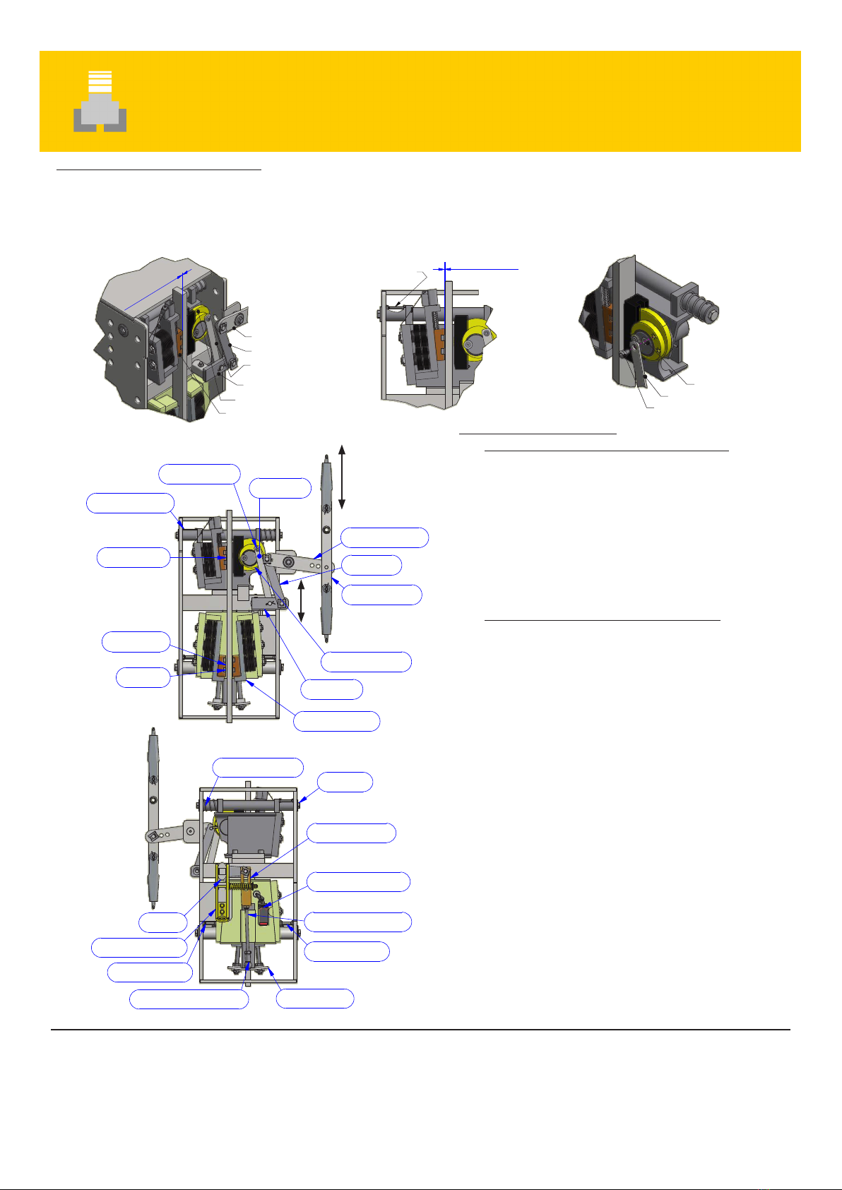
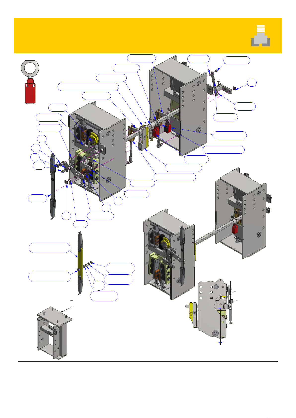
1. It must be possible to turn the actuating shaft manually until the gripping eccentric engages and the
safety gear switch must be actuated. When pulled out from the braking position, the actuating shaft
(gripping eccentric) must turn back into neutral position.
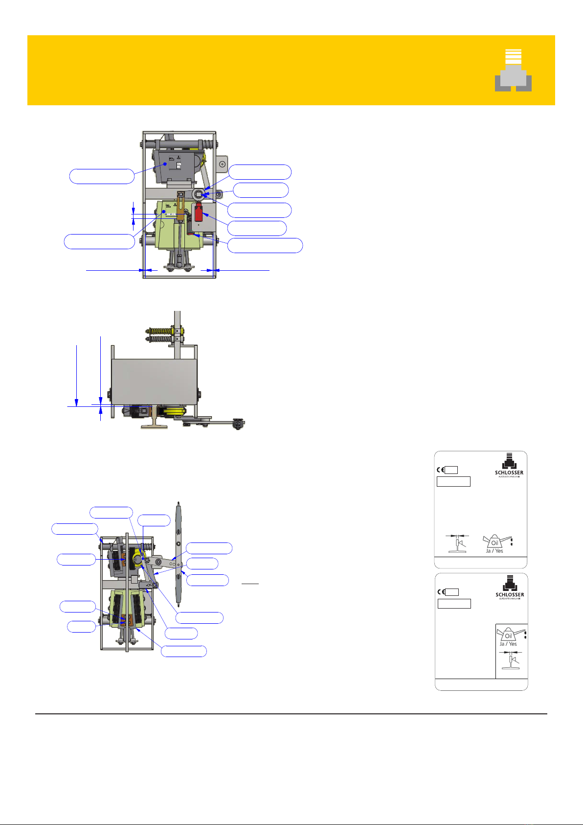
2. The guide rails must only be oiled with specified lubricants. (Observe EC-type examination certificate). No
greases, oils which become resinous etc.
3. Maintenance at least once annually (or operating hours or
contamination).
4. Avoid rust by cleaning and lubricating the moving parts.
5.
6.
7. Check the tractive force of the overspeed governor with required tractive force of the safety gear/safety
module (at least statically).
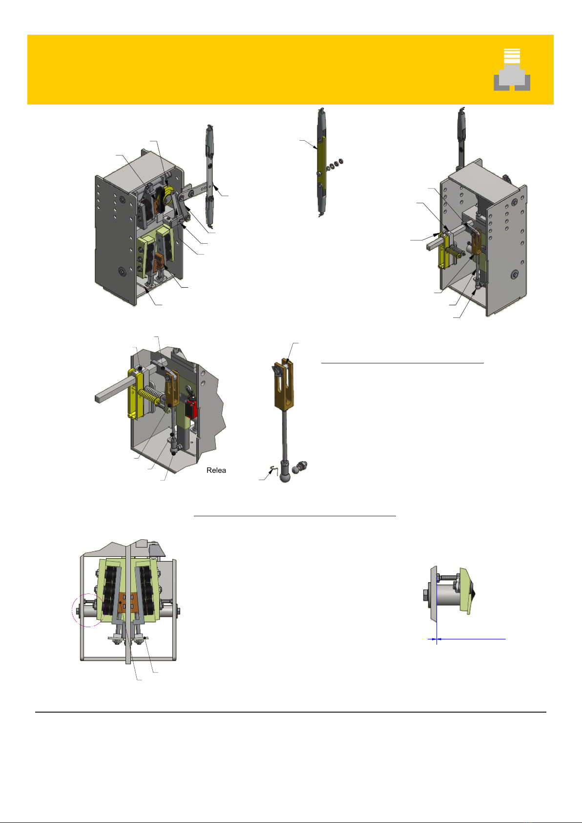
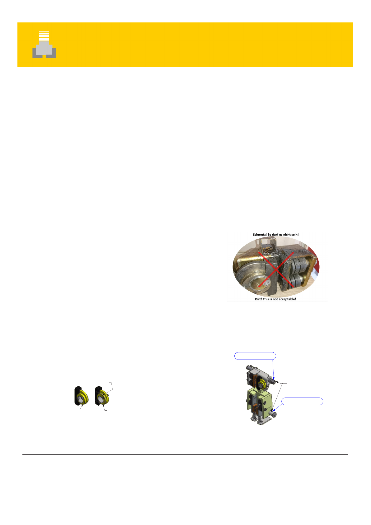
Lubricate all joints, in particular the
spring and the gripping eccentric (if
they are not moving smoothly).
Front Back
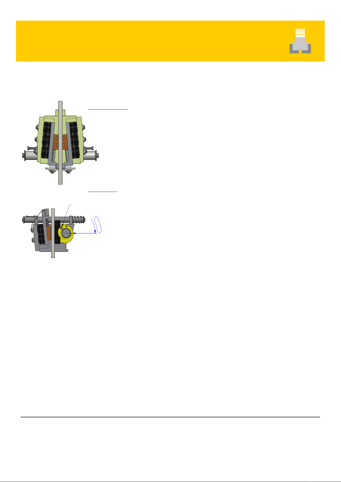
Lubricate between eccentric
and spring steel strip
Kingpin, can be pulled out
It must be easy to move
the safety gear smoothly
on the kingpin.
6.
!Important!
Prior to commissioning:
1. Before commissioning and testing the guide rails must be cleaned thoroughly prior to installation!
Whether „old“ or „new“, (due to dirt, old lubricant or protective agents in case of new rails!), they must
be kept clean both before and after commissioning!!!
2. Should this not take place, negative changes in the braking force etc. can/will occur: In this case, any
potential claim will be rejected.
3. Should „old“ guide rails show very long skid marks or many and deep marks (e.g. from safety gear), they
have to be replaced by new guide rails – of the same type.
4. After recommended test check (only functional test - low speed/empty lift car) a safety test (engagement
test) must be carried out according to the applicable guidelines (e.g. EN 81-20/50), also for „SRMs“
(conveyors), or according to the manufacturer‘s specifications.
Should none of the above provisions apply, the test must be executed in the „downward“ direction at
least with nominal speed and nominal load without any braking of the drive unit (e.g. keep operational
brake open!), otherwise no performance record! In the event of uncertainties, please contact us - as
manufacturer - immediately.
Periodical tests (engagement tests) must also be carried out
at regular intervals.
5. The brake power is assessed by persons with professional
expertise (e.g. inspection bodies etc.).
It must be possible to move the safety gear/safety module
smoothly on the kingpin (floating system).

Schlosser
Aufzugtechnologie GmbH
Felix-Wankel-Straße 4
85221 Dachau
T +49 8131 / 5186-0
www.schlosser.de
Ausgabe
edition
06.09.2018
Seiten
pages
3/7
Bearbeiter
person in charge
Kepplinger
Zeichnung Nr.
drawing nr.
5370.800.003
Combination KB55S/SS-EB75GS
Mounting / Adjustment
A ( 1 : 6 )
B ( 1 : 3 )
A
Press up the
release sliders (5)
until the brake shoes (1) clamp
approx.0,5-1,0 mm clearance
Lock set screw
A ( 1 : 6 )
B ( 1 : 3 )
A
Press up the
release sliders (5)
until the brake shoes (1) clamp
approx.0,5-1,0 mm clearance
Lock set screw
Actuation lever (22)
Actuation tab (23)
Release lever (24)
Release bar (25)
Brake shoe (1)
Release slider (5)
Double eccentric (8)
Brake shoe (10)
Reversing lever (17)
Reset cam (19)
opt. double reset clamp
High speed
Freewheel yoke (16)
Spindle for adjusting M10 (15)
Angle joint (14)
a)
b)
Adjustment:
Turn the thread M10 (15) with the angle joint (14) until
the length to the release slider (5) in adjusted in the open
position (both sides)
Safety gear KB 55S/SS Adjustment of the set screws (M8)
a) Press the release slider (5) up until the brake
shoes (1) are clamped on the guide rail
(centering the safety gear on the guide rail)
b) Then lock the set screws with approx. 0.5 - 1.0
mm clearance (the bolt heads must never
be resting on the external housing)
c) release either by hand or by briefly lifting the
brake shoes (1)
Setting type: KB 55S/SS - working downwards
1. Adjust and set connection between the reversing
lever (17) and the release slider (5) with free-
wheel yoke (16) and spindle for adjusting (15),
angle joint (14).
Attention!
no backlash in neutral
position of brake wedges
Release clip
"installation tip"
A ( 0,20 : 1 )
A
Winkelgelenk (14)
Gleichstellstange M10 (15)
Freilaufgabel (16)
Rückstellnocke (19)
Umlenkerhebel (17)
Angle joint (14)
Spindle for adjusting M10 (15)
Freewheel yoke (16)
Reset cam (19)
Reversing lever (17)
opt.Swivel bar
High speed

B ( 0,15 : 1 )
C ( 0,30 : 1 )
B
C
Bremsbacke (1)
Double eccentric (8)
c
a
.
1
,
0
0
-
2
,
0
0
m
m
Actuation lever (22)
Actuation tab (23)
Release lever (24)
Actuation bar (25)
Brake shoe (10)
Schlosser
Aufzugtechnologie GmbH
Felix-Wankel-Straße 4
85221 Dachau
T +49 8131 / 5186-0
www.schlosser.de
Ausgabe
edition
06.09.2018
Seiten
pages
4/7
Bearbeiter
person in charge
Kepplinger
Zeichnung Nr.
drawing nr.
5370.800.004
Combination KB55S/SS-EB75GS
Mounting / Adjustment / Check
B ( 0,30 : 1 )
C ( 0,30 : 1 )
D ( 0,20 : 1 )
B
C
D
Bremsbacke (1)
Doppelexzenter (8)
1,0 - 2,0mm
Adjusting screw M6
A ( 0,20 : 1 )
A
Lockwasher
Release bar (25)
Releasing bolt M8
Actuation lever (22)
Release wire (26)
Douple eccentric (8)
Release lever
Actuation bar
Actuating bar
Releasing bolt M8
Adjusting screw M6
Brake shoe (10)
Brake shoe (1)
Brake pads
Brake shoe retainer
Kingpin (12)
Freewheel yoke (16)
Freewheel switcher (32)
Spindle for adjusting (15)
Adjusting screw M8
Release slider (5)
Angle joint with spindle M10
Adjusting screw M8
Reset cam
Resetting bracket (18)
Resetting spring (29)
Positioner sleeve
Switching cam (21)
Actuating shaft (28)
Safety switch (27)
Freewhell switcher (32)
Air 0.5-1.00mm
ca.250
ca.268
ca.292
1-2mm
Brake shoe retainer
Brake shoe
Lead seals
Kingpin KB55S/SS
Lead seal
Kingpin EB75GS
Actuation lever (22)
Release wire (26)
Douple eccentric (8)
Release lever
Actuation bar
Brake shoe retainer
Kingpin (12)
Freewheel yoke (16)
Freewheel switcher (32)
Spindle for adjusting (15)
Adjusting screw M8
Release slider (5)
Angle joint with spindle M10
Adjusting screw M8
Reset cam
Resetting bracket (18)
Resetting spring (29)
Positioner sleeve
Switching cam (21)
Actuating shaft (28)
Safety switch (27)
Freewhell switcher (32)
Air 0.5-1.00mm
ca.250
ca.268
ca.292
1-2mm
Brake shoe retainer
Brake shoe
Lead seals
Kingpin KB55S/SS
Lead seal
Kingpin EB75GS
Setting type: EB 75 GS - acting upwards
1. Adjust the braking device and guide rail using the adjusting screw (M6) until a clearance of 1 - 2 mm between the brake shoe (10) and
the rail is set, then lock.
2. Mount the release bar (25) with lockwasher on double eccentric (8) to the top borehole (thread M8) using the releasing bolt (M8)
Mounting / adjustment / check
1. Setting type KB 55S/SS to synchronous running
k Push up (engagement downwards) the actuation lever
(22) until the brake shoes (1) clamp on the guide rail
(press).
Check:
The brake shoes (1) must clamp (press) in both safety gears. If
not, the spindles (15) must be adjusted (some lead of the brake
shoes (1) opposite the Actuation lever (22) is an advantage)!
2. Check type EB 75 GS for synchronous running
l Press down (brake upwards) the actuating lever (22)
until both double eccentrics (8) are pressed onto the guide
rails.
Check: If not: Change clearance 1-2 mm between brake
shoe (10) and guide rail slightly by adjusting the adjusting
screw (M6).
Note: A test run provides clarity! Slow raising of the system (test
run) with activation of the actuation lever (22) until the double
eccentrics (8) turn in automatically. Stop the system immediately
when the double eccentrics turn in!
Then check that both double eccentrics (8) have clamped. Lower
the system to release! Both brake mechanisms must reset auto-
matically via the reset spring (29) and the kingpin (12)!
3. Attachment of the release cable coupling (26) – „Long
side“ up!
4. Adjusting the reset clamping spring (18). Select the preten-
sion to ensure normal operation. Observe the pull-in forces
of the release components, e.g. overspeed governor! (The
pull-in force must be double that of the safety module at
the overspeed governor!)
DOWNUP
DOWNUP
Front view
Back view

Combination KB55S/SS-EB75GS
Mounting / Information
Schlosser
Aufzugtechnologie GmbH
Felix-Wankel-Straße 4
85221 Dachau
T +49 8131 / 5186-0
www.schlosser.de
Ausgabe
edition
06.09.2018
Seiten
pages
5/7
Bearbeiter
person in charge
Kepplinger
Zeichnung Nr.
drawing nr.
5370.800.005
3 - max.5mm
STM/DBG
Actuation lever (22)
Release wire (26)
Douple eccentric (8)
Release lever
Actuation bar
Actuating bar
Releasing bolt M8
Adjusting screw M6
Brake shoe (10)
Brake shoe (1)
Brake pads
Brake shoe retainer
Kingpin (12)
Freewheel yoke (16)
Freewheel switcher (32)
Spindle for adjusting (15)
Adjusting screw M8
Release slider (5)
Angle joint with spindle M10
Adjusting screw M8
Reset cam
Resetting bracket (18)
Resetting spring (29)
Positioner sleeve
Switching cam (21)
Actuating shaft (28)
Safety switch (27)
Freewhell switcher (32)
Air 0.5-1.00mm
ca.250
ca.268
ca.292
1-2mm
Brake shoe retainer
Brake shoe
Lead seals
Kingpin KB55S/SS
Lead seal
Kingpin EB75GS
KB55S
EU-SG 374
Date: -
UCM: NL12-400-1002-169-02 Rev.1
Serial-Nu.: -
Tripping spd. max: - m/s
Guide head: -
----
Aufzugtechnologie G.Schlosser GmbH
Felix-Wankel-Str.4, 85221 Dachau
Weight=: - kg
EB75GS
EU-SG 289
Date: -
UCM: NL12-400-1002-169-05 Rev.1
Serial-Nu.: -
Tripping spd. max: - m/s
Brake force=43800-49999N
Guide head: -
----
Aufzugtechnologie G.Schlosser GmbH
Felix-Wankel-Str.4, 85221 Dachau
Actuation lever (22)
Release wire (26)
Douple eccentric (8)
Release lever
Actuation bar
Brake shoe retainer
Kingpin (12)
Freewheel yoke (16)
Freewheel switcher (32)
Spindle for adjusting (15)
Adjusting screw M8
Release slider (5)
Angle joint with spindle M10
Adjusting screw M8
Reset cam
Resetting bracket (18)
Resetting spring (29)
Positioner sleeve
Switching cam (21)
Actuating shaft (28)
Safety switch (27)
Freewhell switcher (32)
Type plate KB55S/SS
Type plate EB75GS
Air 0.5-1.00mm Air 0.5-1.00mm
~5-10mm
ca.250
ca.268
ca.292
1-2mm
Brake shoe retainer
Brake shoe
Lead seals
Kingpin KB55S/SS
Lead seal
Kingpin EB75GS
KB55
EU-SG333
Datum:
-
UCM: NL12-400-1002-169-01Rev.1
Fabrik-Nr.: -
V
auslösemax: - m/s
Schienenkopf: -
----
AufzugtechnologieG.Schlosser GmbH
Felix-Wankel-Str.4,85221Dachau
Masse
=: -kg
EB75KS
EU-SG313
Datum: -
UCM: NL12-400-1002-169-04Rev.1
Fabrik-Nr.: -
Vauslösemax: - m/s
Bremskraft=25490-29399N
Schienenkopf: -
----
AufzugtechnologieG.Schlosser GmbH
Felix-Wankel-Str.4,85221Dachau
Make sure that the immersion depth of the rail is
correct.
• 3 - max. 5mm
The safety module lk may only be installed if the
values indicated on the type plate correspond to the
lift data. Check that the lead sealing is undamaged.
Attention: Strictly avoid any contact with the guide
rail in case of spring-loaded guiding elements!
(Observe spring deflections!, otherwise unintended
engagement etc!)
Note:
For larger lifts!/loads etc. (forklift operation!) make
sure that the guide rails and the load-bearing
components are stable. Safety gears etc. must not
be pressed onto the guide rail by loading activity or
one-sided loading of the lift! This is because the later
enlargement of the clearance is often not possible.
Adjustment and setting of the safety switch (27)
Position the safety switch in such a way with respect to the
switching cam (21) that slight vertical movements of the
actuating shaft (28) do not cause the system to switch, but
only when the release shaft turns!
Note: Make sure that the free wheel switcher (32) switch before
the brake shoe (1) is clamped/pressed onto the guide rail!
Tip: Gap between the switching part and release slider (5)
approx. 5 – 10 mm!
Back view
of opposite

Combination KB55S/SS-EB75GS
Check
Schlosser
Aufzugtechnologie GmbH
Felix-Wankel-Straße 4
85221 Dachau
T +49 8131 / 5186-0
www.schlosser.de
Ausgabe
edition
06.09.2018
Seiten
pages
6/7
Bearbeiter
person in charge
Kepplinger
Zeichnung Nr.
drawing nr.
5370.800.006
Clearance between
the spring wires
when fully opened
Attention:
Adjust the resetting spring in such a way that
the pull-in forces are not too high and to
ensure sufficient spring deflections.
Test in detail
DOWNWARDS:
a) 1,25 times nominal load and nominal speed
b) or nominal load and with tripping speed
c) Keep brake open!
Note:
To make it easier to draw the car out of the engagement, it is recommended to
carry out the test near a door so that the load from the car can be discharged
there.
UPWARDS:
a) Empty car with min. nominal speed without any braking aid
(operational brake open, drive system switched off
After the test, make sure that no damage has occurred that could impair the
normal operation of the lift. If necessary, brake shoes can be replaced. Visual
examination is considered sufficient.
The objective of the test prior to commissioning is to determine the proper as-
sembly, the correct adjustment and the strength of the functional unit, comprising
the car - safety gear - guide rails - rail mountings.
Tripping/engagement forces:
At least double the required pull-in force lk of the safety gear/safety module
but at least 300N in both directions lk.
Reading
of marks
Threshold
distance
Braking distance
Threshold
distance Braking distance
S c o r i n g
Knurling marks
Downwards
Upwards
(Hard metals)
(Double eccentric)

Combination KB55S/SS-EB75GS
Test instructions / information
Schlosser
Aufzugtechnologie GmbH
Felix-Wankel-Straße 4
85221 Dachau
T +49 8131 / 5186-0
www.schlosser.de
Ausgabe
edition
06.09.2018
Seiten
pages
7/7
Bearbeiter
person in charge
Kepplinger
Zeichnung Nr.
drawing nr.
5370.800.007
11 o´clock
Release
Pulling out of the lengagement kbrake position.
Downwards
lEngagement position: the brake shoes are pulled in upwards!
Pull off the lengagement position in steps:
- Start quickly in upward direction using the re-levelling control.
- Several repetitions = in principle: loosen and tighten ropes
- Handwheel aid
- Empty the car
- Traction sheave clamp, lifting etc.
Upwards
kBrake position: The M8 bore hole of the double eccentric shows approx. 11 o‘clock.
Pull off the kbrake position in steps:
- Start quickly in downward position using the re-levelling control.
- Several repetitions = in principle: loosen and tighten ropes.
- Handwheel aid
- Load the car
- Traction sheave clamp, car hanging freely etc.
Note:
1. In the case of weightless testing downwards (electronic test device), the bouncing of the cabin can cause the
brake to fall back or be pulled into the upwards braking position! (Bouncing counterweight!).
2. Also, a release from the upwards braking position can cause the brake to fall back or be pulled into the down-
wards direction! (Jerky release from above!).
Note:
The release of the cabin from the downwards braking position tends to be more difficult, the „lighter“ the cabin is
in relation to the nominal load. (Heavy counterweight to light cabin!).
Liability and guarantee:
The company Aufzugtechnologie Schlosser does not accept any liability or provide any guarantee for damages
resulting from incorrect handling or inappropriate use of our products contrary to these instructions.

Clip
Auslöseschraube
Federring
Auslöselasche
Sicherungsstift
Freilaufschalter
Freilaufgabelsystem
Fangschalter
Rückstellklammer stark
Umlenkerhebel
opt.Doppelrückstellklammer High speed
Stellbuchse
Kontaktgeber
Federring
Auslöseschraube
Auslöselasche
Auslösehebel
Clip
Scheibe
Betätigungshebel
Betätigungslasche
Schraube
Scheibe
Clip
Scheibe
Distanzscheibe
Clip
Auslöseseilhebel
Clip
Releasing bolt
Lockwasher
Actuating bar
Locking pin
Freewheel switcher
Freewheel yoke system
Safety switch
Reset bracket strong
Reversing lever
opt. double reset clamp High speed
Positioner sleeve
Switching cam
Lockwash
Releasing bolt
Actuating bar
Release lever
Clip
Disk
Actuation lever
Actuating bar
Screw
Disk
Clip
Disk
Spacer
Clip
Swivel bar
Reversing lever
Freewheel yoke system
Assembly of actuating gear
KB55S/SS-EB75GS
Schlosser
Aufzugtechnologie GmbH
Felix-Wankel-Straße 4
85221 Dachau
T +49 8131 / 5186-0
www.schlosser.de
Ausgabe
edition
06.09.2018
Seiten
pages
1
Bearbeiter
person in charge
Kepplinger
Zeichnung Nr.
drawing nr.
5370.800.010
• Starting condition
• Final
Detail release lever/
actuating bar
Half nut M12
Half nut M12
Disk
Rubber ring
6KT screw M12x40
Option high speed
Alternativ detachable
outer housing
B
C
Release lever (24)
Actuation tab (23)
Release bar (25)
Brake shoe (1)
Release slider (5)
Brake shoe (10)
Double eccentric (8)
min.0,50 - max.1,00mm
Clearance with min.0,5 -
max.1,0mm on each side
in drilled release lever
Screw connection
from above
This manual suits for next models
4
Table of contents
Other Schlosser Safety Equipment manuals