manuals.online logo
Brands
  1. Home
  2. •
  3. Brands
  4. •
  5. schmersal
  6. •
  7. Controllers
  8. •
  9. schmersal AZ 15-B1 User manual

schmersal AZ 15-B1 User manual

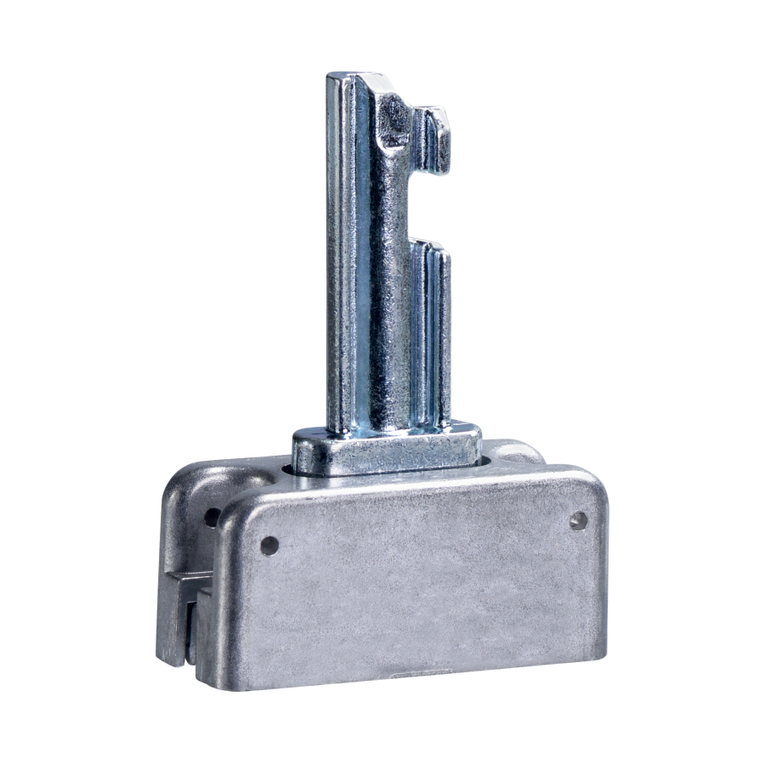
Montageanleitung / Betätiger
Mounting instructions / Actuators
Instructions de montage / Actionneurs
AZ 15/AZ 16
EEx AZ 16
Hinweis
Verwenden Sie als Sicherung gegen unbefugtes Lösen Sicherheits-
schrauben mit Einwegschlitz, als Zubehör erhältlich. Bei Befesti-
gung, z.B. durch Nieten oder Schweißen, ist darauf zu achten, dass
sich die Eintauchtiefe des Betätigers nicht ändert.
Es stehen verschiedene Betätigerformen zur Verfügung: Vorzugs-
weise für verschieb- und abnehmbare Schutzeinrichtungen der
Betätiger AZ 15/16-B1. Für drehbare Schutzeinrichtungen die
Betätiger AZ 15/16-B2, -B3 und -B6.
Montage
Bei der Montage an drehbaren Schutzeinrichtungen ist darauf zu ach-
ten, dass der Drehpunkt in der Ebene der Oberfläche des Sicher-
heitsschalters liegt, in die der Betätigungsbügel eintaucht (s. Tabelle).
AZ 15/16-B1-2245 gummigelagert
Max. 200 Ncm Anzugsdrehmoment bei der Montage des Betätigers
Einstellschraube
Werkseitig ist der Betätiger auf den kleinsten Radius eingestellt. Bei
größeren Radien die Einstellung durch Drehen der Einstellschrauben
a (AZ 15/16-B2), b (AZ 15/16-B3) und a+b (AZ 15/16-B6) mit einem
Innensechskant-Schlüssel SW 2,5 mm.
Notice
Please ensure this is fitted the correct way round, and tighten the
actuator with one-way screws (available as accessory), to prevent
deliberate removal. Please ensure with welding or riveting of the
actuator, that the insertion depth of the actuator is not altered.
There are different actuator types available, depending on the appli-
cation. The actuator AZ 15/16-B1 is designed for sliding and remo-
vable safety guards, while AZ 15/16-B2, -B3 and -B6 are recom-
mended for hinged safety guards.
Mounting
Please note, that the centre of rotation must be in the same plane
as the upper edge of the safety switch (see table).
AZ 15/16-B1-2245 with rubber mountings
max. 200 Ncm tightening torque for mounting the actuator
Set screw
The basis setting provides a minimum radius. For larger radii, the
angle has to be adjusted correspondingly by turning the set screws
a (AZ 15/16-B2), b (AZ 15/16-B3) and a+b (AZ 15/16-B6), using an
hexagonal key wrench 2.5 mm A/F.
Remarque
Pour éviter tout démontage intempestif, utiliser les vis à tête fraisée
avec vissage unidirectionnelle, peut être fourni comme accessoire.
En cas de fixation selon un mode différent, par exemple par rivetage
ou soudage, veiller à ce que la profondeur de plongée de l'acion-
neur ne varie. Different formes d’actionneurs sont disponibles. Le
actionneur AZ 15/16-B1 sont recommandés pour les protecteurs
coulissants et amovibles. Dans le cas de protecteurs pivotants, nous
vous conseillons l’actionneur AZ 15/16-B2, -B3 et -B6.
Montage
Lors du montage sur des protecteurs pivotants, veiller à ce que
l'axe de rotation se trouve dans le plan de la surface de l'inter-
rupteur de sécurité dans laquelle l'actionneur plonge (voir table).
AZ 15/16-B1-2245 avec amortisseur en caoutchouc
Couple de serrage de l'actionneur: maxi 200 Ncm
Vis de réglage
Le réglage de base est établi en fonction du plus petit rayon. Dans
le cas de rayons plus grands, modifier le réglage en tournant la vis
de réglage a (AZ 15/16-B2), b (AZ 15/16-B3) et a+b (AZ 15/16-B6)
à l'aide d'une clé 6 pans de 2,5 mm sur plats.
deutsch
english
français
Rmin [mm] x [mm] Rmin [mm] x [mm]
AZ 15/16-B1 150 5 150 5
AZ 15/16-B1-2245 150 14 150 14
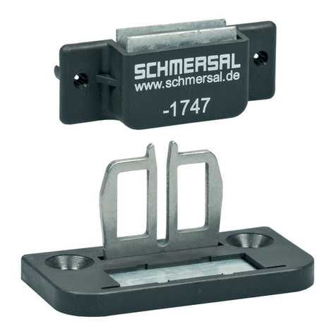
AZ 15/16-B1-1747 150 5 150 5
AZ 15/16-B1-2024 150 11 150 11
AZ 15/16-B1-2053 150 11 150 11
AZ 15/16-B1-2177 150 11 150 11
AZ 15/16-B2 – – 45 11
AZ 15/16-B2-1747 – – 45 11
AZ 15/16-B3 32 11 – –
AZ 15/16-B3-1747 32 11 – –
AZ 15/16-B6 25 11 38 11
Der Drehpunkt des Scharniers und Oberkante des Sicherheits-
schalters müssen zuzüglich x mm eine Ebene bilden. Die Grund-
einstellung ist auf den kleinsten Radius Rmin eingestellt.
The axis of the hinge must be x mm above and in a parallel plane
to the top surface of the safety switch. The basis setting provides
a minimum radius of Rmin.
L'axe de rotation de l'articulation et la face supérieure de l’inter-
rupteur de sécurité doivent se situer dans deux plans parallèles
distants de x mm. Le réglage de base est établi en fonction du
plus petit rayon, Rmin.
Rmin.
x
Rmin.
x
Betätigungsradien
Actuator radii
Rayons d'actionnement
Einstellschraube
Set screw
Vis de réglage
ab
a
a
bb
Radien über die breite Seite des Betätigers
Radii over the wide edge of the actuator
Rayons d'actionnement sur le grand côté
de l'actionneur
Radien über die schmale Seite des Betätigers
Radii over the small edge of the actuator
Rayons d'actionnement sur le petit côté
de l'actionneur
Rmin.
x
Rmin.
x
Legende
Legend
Légende
m_z15b05.qxd 23.05.2002 8:57 Uhr Seite 1
Istruzioni di montaggio / Attuatori
Instrucciones de montaje / Actuadores AZ 15/AZ 16
EEx AZ 16
Avvertenza
Per evitare uno smontaggio non autorizzato o manomissioni
utilizzare viti di sicurezza con intaglio antisvitamento, disponibili
come accessori. Durante il fissaggio, ad esempio mediante rivetti o
saldatura, assicurarsi che la profondità di inserimento dell'attuatore
non venga alterata.
Sono disponibili diversi tipi di attuatori: per protezioni scorrevoli e
amovibili è da preferirsi l'attuatore AZ 15/16-B1, per protezioni a
cerniera gli attuatori AZ 15/16-B2, -B3 e -B6.
Montaggio
In caso di montaggio su protezioni a cerniera assicurarsi che il fulcro
si trovi sullo stesso piano della superficie dell'interruttore di sicurezza
nel quale la leva di azionamento affonda (vedi tabella).
AZ 15/16-B1-2245 su gomma
Coppia di serraggio per il montaggio dell'attuatore max. 200 Ncm
Vite di regolazione
L'attuatore è tarato sul raggio minimo. Per raggi maggiori modificare
la taratura agendo sulle viti di regolazione „a“ (AZ 15/16-B2),
„b“ (AZ 15/16-B3) e „a+b“ (AZ 15/16-B6) con una chiave a brugola
da 2,5 mm.
Observaciones
Con el fin de evitar el desmontaje indebido, utilizar los tornillos de
cabeza fresada, que solo permiten su accionamiento en un solo
sentido, disponibles bajo demanda. En caso de fijación con un
sistema distinto, remachado, o soldado, hay que procurar mantener
la profundidad de penetración original. Existen distintas formas de
actuadores disponibles. Los actuadores AZ 15/16 – B1 se reco-
miendan en puertas deslizantes o desmontables. En caso de puer-
tas pivotantes, se recomiendan los AZ 15/16-B2,-B3, y -B6.
Montaje
Al montarse en puertas pivotantes, se debe tener en cuenta que el
eje de giro debe estar en el plano de la superficie del interruptor de
seguridad en la que éste penetre. (Ver tabla).
AZ 15/16-B1-2245 con amortiguadores de goma
Par de apriete máximo del actuador: 200 Ncm
Tornillo de regulación
La regulación básica se establece en función del radio mínimo. En
caso de radios mayores, debe modificarse la regulación por medio del
tornillo de regulación „a“ (AZ 15/16-B2), „b“ (AZ 15/16-B3), y „a + b“
(AZ 15/16-B6) mediante una llave hexagonal de 2,5 mm entre caras.
italiano
español
Rmin [mm] x [mm] Rmin [mm] x [mm]
AZ 15/16-B1 150 5 150 5
AZ 15/16-B1-2245 150 14 150 14
AZ 15/16-B1-1747 150 5 150 5
AZ 15/16-B1-2024 150 11 150 11
AZ 15/16-B1-2053 150 11 150 11
AZ 15/16-B1-2177 150 11 150 11
AZ 15/16-B2 – – 45 11
AZ 15/16-B2-1747 – – 45 11
AZ 15/16-B3 32 11 – –
AZ 15/16-B3-1747 32 11 – –
AZ 15/16-B6 25 11 38 11
Il fulcro della cerniera e il bordo superiore dell'interruttore di
sicurezza devono essere su due piani paralleli distanti fra loro x mm.
Al montaggio la taratura è fissata sul raggio minimo Rmin.
El eje de giro de la bisagra, y la cara superior del interruptor de seguri-
dad deben situarse en dos planos paralelos, separados por x mm.
El reglaje de base viene establecido en función del radio mínimo, Rmin.
Rmin.
x
Rmin.
x
Raggi d'azionamento
Radios de accionamiento
Vite di regolazione
Tornillo de regulación
ab
a
a
bb
x.000 / v.A. / 05.02 /Ident-Nr. 5122213000 / BZ 50094-111.00 / Ausgabe C
Raggi sul lato lungo dell'attuatore
Radios de accionamiento en el lado
mayor del actuador
Raggi sul lato corto dell'attuatore
Radios de accionamiento en el lado
menor del actuador
Rmin.
x
Rmin.
x
Legenda
Leyenda
K.A.Schmersal GmbH
Industrielle Sicherheitsschaltsysteme
Möddinghofe 30, D-42279 Wuppertal
Postfach 24 02 63, D-42232 Wuppertal
Telefon +49-(0)202-6474-0
Telefax +49-(0)202-6474-100
E-Mail: [email protected]
Internet: http://www.schmersal.com
m_z15b05.qxd 23.05.2002 8:57 Uhr Seite 2

This manual suits for next models

21

Other schmersal Controllers manuals

schmersal AZ15-B1 Operation and maintenance manual

schmersal

schmersal AZ15-B1 Operation and maintenance manual

schmersal PROTECT SELECT User manual

schmersal

schmersal PROTECT SELECT User manual

schmersal AZM 161 Series User manual

schmersal

schmersal AZM 161 Series User manual

schmersal AZ/AZM 415 User manual

schmersal

schmersal AZ/AZM 415 User manual

schmersal PSC1 Series User manual

schmersal

schmersal PSC1 Series User manual

schmersal SRB 031LC/0.6 sec User manual

schmersal

schmersal SRB 031LC/0.6 sec User manual

schmersal AES 2285 User manual

schmersal

schmersal AES 2285 User manual

schmersal AES 1135 User manual

schmersal

schmersal AES 1135 User manual

schmersal SRB 207AN User manual

schmersal

schmersal SRB 207AN User manual

schmersal AZM 161 I Series User manual

schmersal

schmersal AZM 161 I Series User manual

schmersal EX-RDRZ45 RT User manual

schmersal

schmersal EX-RDRZ45 RT User manual

Popular Controllers manuals by other brands

Texas Instruments TMS320C6000 DSP reference guide

Texas Instruments

Texas Instruments TMS320C6000 DSP reference guide

Honeywell Home R8182H installation instructions

Honeywell Home

Honeywell Home R8182H installation instructions

Industrial Shields ESP32 user guide

Industrial Shields

Industrial Shields ESP32 user guide

ascon e33 operating instructions

ascon

ascon e33 operating instructions

Emerson DIXELL XR30T Installing and operating instructions

Emerson

Emerson DIXELL XR30T Installing and operating instructions

Gira KNX 2139 00 Product documentation

Gira

Gira KNX 2139 00 Product documentation

Braglia M202 Installation, use and maintenance

Braglia

Braglia M202 Installation, use and maintenance

LAE SMD34RU Instructions for installation and use

LAE

LAE SMD34RU Instructions for installation and use

Edgewater Networks EdgeMarc 4576 installation guide

Edgewater Networks

Edgewater Networks EdgeMarc 4576 installation guide

Carel universal infrared series user manual

Carel

Carel universal infrared series user manual

Deif Multi-line 2 Designers reference handbook

Deif

Deif Multi-line 2 Designers reference handbook

Topcon Norac UC5 installation manual

Topcon

Topcon Norac UC5 installation manual

AquatiControl Technology ELC-810 Series Operation and maintenance manual

AquatiControl Technology

AquatiControl Technology ELC-810 Series Operation and maintenance manual

Ingersoll-Rand ST400 Series Product information

Ingersoll-Rand

Ingersoll-Rand ST400 Series Product information

Omron E5 Z Series manual

Omron

Omron E5 Z Series manual

EUCHIPS DMX-E05 manual

EUCHIPS

EUCHIPS DMX-E05 manual

Edgewater Networks EdgeMarc 4571 installation guide

Edgewater Networks

Edgewater Networks EdgeMarc 4571 installation guide

Elmos E520.30 manual

Elmos

Elmos E520.30 manual

manuals.online logo
manuals.online logoBrands
  • About & Mission
  • Contact us
  • Privacy Policy
  • Terms and Conditions

Copyright 2025 Manuals.Online. All Rights Reserved.