3
AZM 161../..
Operating instructions
Solenoid interlock
EN
The entire concept of the control system, in which the
safety component is integrated, must be validated to the
relevant standards.
The user must evaluate and design the safety chain in
accordance with the relevant standards and the required
safety level.
2.4 Technical data
Standards: IEC 60947-5-1, ISO 14119, BG-GS-ET-19
Enclosure: glass-fibre reinforced thermoplastic, self-extinguishing
Actuator and locking bolt: stainless steel 1.4301
Holding force F: 2,000 N
Latching force: 30 N for ordering suffix R
Coding level according to ISO 14119: low
Protection class: IP67
Contact material: Silver
Contact type: Change-over contact with double break type Zb,
with galvanically separated contact bridges
Switching system:
A
acc. IEC 60947-5-1 slow action,
NC contact with positive break
Connection: screw terminals or cage clamps or connector plug
Cable type: flexible
Cable section: min. 0.25 mm², max. 1.5 mm²
(including conductor ferrules)
Cable entry: 4 x M16
Positive break travel (unlocked): 10 mm
Positive break force (unlocked): 10 N for each NC contact fitted
Actuating speed: max. 2 m/s
Actuating frequency: max. 1,000 operations/h
Mechanical life: > 1 million operations
Ambient temperature: −25 °C … +60 °C
Electrical data:
Utilisation category: AC-15, DC-13
Rated operating current / voltage Ie/Ue:4 A / 230 VAC
2.5 A / 24 VDC
- ST 4-pole: 4 A / 230 VAC
4 A / 24 VDC
- ST 8-pole: 2 A / 24 VDC
Rated impulse withstand voltage Uimp:4 kV
- Connector ST 4-pole: 2.5 kV
- Connector ST 8-pole: 0.8 kV
Rated insulation voltage Ui:250 V
- Connector ST 4-pole: 250 V
- Connector ST 8-pole: 60 V
Thermal test current Ithe:6 A
- Connector 4-pole: 4 A
- Connector 8-pole: 2 A
Max. fuse rating: 6 A gG D-fuse
- Connector 4-pole: 4 A gG D-fuse
- Connector 8-pole: 2 A gG D-fuse
Required rated short-circuit current: 1,000 A
Rated control voltage Us:24 VDC
24 VAC / 50/60 Hz
110 VAC / 50/60 Hz
230 VAC / 50/60 Hz
Electrical data – Magnet control:
Magnet switch-on time: 100 %
Power consumption: max. 10 W
Accepted test pulse duration on input signal: ≤ 5.0 ms
- With test pulse interval of: ≥ 50 ms
Use Type 4X (Indoor Use) and 12 connector fittings.
Tightening torque rating: 4.4 lb in.
2.5 Safety classification of the interlocking function
Standards: ISO 13849-1
Envisaged structure:
- Basically: applicable up to Cat. 1 / PL c
- With 2-channel usage and
fault exclusion mechanism*: applicable up to Cat. 3 / PL d
with suitable logic unit
B10D NC contact: 2,000,000
B10D NO contact at 10% ohmic contact load: 1,000,000
Mission time: 20 years
* If a fault exclusion to the 1-channel mechanics is authorised.
TF
D
10Dopop
op
n
(Determined values can vary depending on the application-specific
parameters hop, dop and tcycle as well as the load.)
If multiple safety components are wired in series, the Performance
Level to ISO 13849-1 will be reduced due to the restricted error
detection under certain circumstances.
2.6 Safety classification of the guard locking function
If the device is used as an interlock for personal safety, a safety
classification of the guard locking function is required.
When classifying the guard locking function, a distinction must be
made between monitoring of the interlocking function and control of the
release function.
The following classification of the release function is based on the
principle of isolating the supply of power to the solenoid.
The classification of the release function is only valid for
devices with monitored guard locking function and in the
power to unlock version (see ordering code).
By reliably isolating the power externally, it can be assumed that no
errors can occur with regard to the locking device of the interlock.
In that case, the locking device of the interlock does not contribute
towards the failure probability of the release function.
The level of safety of the release function relies, therefore, exclusively
on reliable external deactivation of the power.
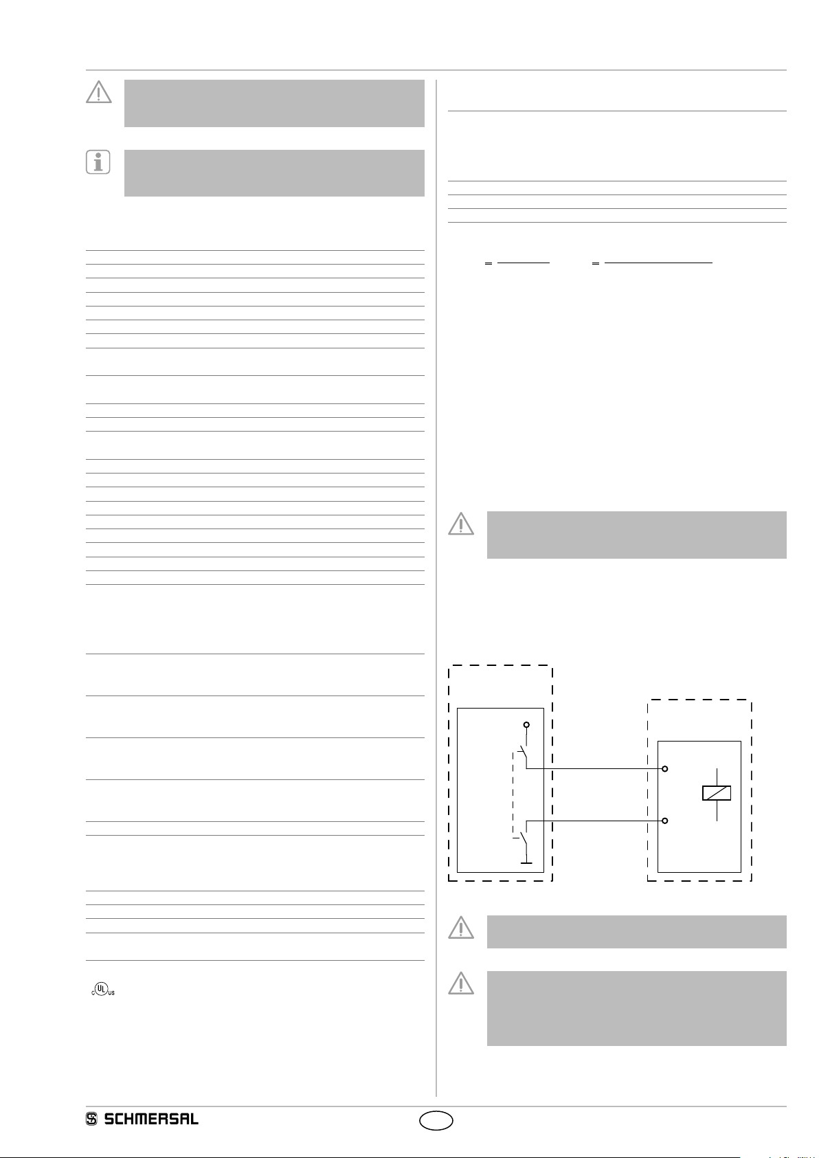
A1
A2
+24 VDC
PL ?
PFHd?
0 VDC
Safety power
shutdown
Solenoid
interlocks
Guard locking
function
Fault exclusion with regard to wiring routing must be
observed.
If for a certain application the power to unlock version
of a solenoid interlock cannot be used, for this exception
an interlock with power to lock can be used if additional
safety measure need to be realised that have an equivalent
safety level.