2
Operating instructions
Safety sensor EX-CSS 180
EN
1.6 Warning about misuse
In case of improper use or manipulation of the safety
switchgear, personal hazards or damages to machinery
or plant components cannot be excluded. The relevant
requirements of the standard ISO 14119 must be observed.
1.7 Exclusion of liability
We shall accept no liability for damages and malfunctions resulting from
defective mounting or failure to comply with this operating instructions
manual. The manufacturer shall accept no liability for damages
resulting from the use of unauthorised spare parts or accessories.
For safety reasons, invasive work on the device as well as arbitrary
repairs, conversions and modifications to the device are strictly
forbidden; the manufacturer shall accept no liability for damages
resulting from such invasive work, arbitrary repairs, conversions and/or
modifications to the device.
2. Product description
2.1 Ordering code
This operating instructions manual applies to the following types:
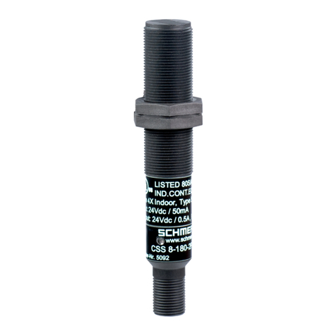
EX-CSS 8-180-2P+D-M-L-3G/D
2.2 Special versions
For special versions, which are not listed in the order code below 2.1,
these specifications apply accordingly, provided that they correspond to
the standard version.
2.3 Purpose
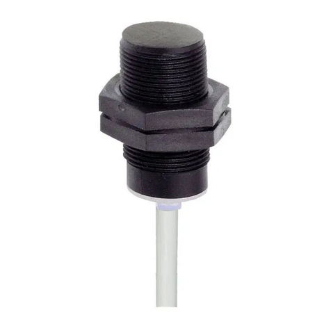
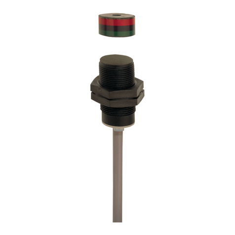
This non-contact, electronic safety sensor is designed for application
in safety circuits and is used for monitoring the position of movable
safety guards. In this application, the safety sensor monitors the closed
position of hinged, sliding or removable safety guards by means of the
coded electronic CST 180-1 or CST 180-2 actuators.
The components can be used in explosion-endangered areas of Zone
2 and 22 equipment category 3 GD. The installation and maintenance
requirements to the standard series EN 60079 must be met.
Conditions for safe operation
Due to their specific impact energy, the components must be fitted
with a protection against mechanical stresses. The specific ambient
temperature range must be observed. The user must provide for a
protection against the permanent influence of UV rays.
Mode of operation of the safety outputs
The opening of a safety guard, i.e. the actuator is removed out of the
active zone of the safety sensor, will immediately disable the safety
outputs (also refer to Switching distance of the safety sensor).
Faults which no longer guarantee the functioning of the safety sensor
(internal fault,) will also disable the safety outputs immediately. Any
error that does not immediately affect the safe functioning of the safety
sensor (e.g. the ambient temperature too high, interference potential
at a safety output, cross-wire short) will lead to a delayed shut-down.
In this situation, the diagnostic output will be switched off after approx.
10 seconds. The safety outputs are disabled when the fault is active
for 1 minute. Signal combination, diagnostic output disabled and
safety outputs still enabled, can be used to shut down the machine in
a controlled manner. After fault rectification, the error message is reset
by opening and re-closing the corresponding safety guard. The safety
outputs will switch, thus enabling the machine. For the release, the chain
of sensors must be permanently actuated.
A cross-wire short at the safety outputs of a sensor chain will
load the sensor from the place where the fault is located up
to the end of the chain. The fault therefore can be signalled
by multiple sensors. Starting from the safety-monitoring
module, the cross-wire short is located before the first sensor
signalling the fault.
Series wiring
Max. 16 sensors can be wired in series.
Wiring examples for series-wiring, refer to appendix
The user must evaluate and design the safety chain in
accordance with the relevant standards and the required
safety level. If multiple safety sensors are involved in the
same safety function, the PFH values of the individual
components must be added.
The entire concept of the control system, in which the safety
component is integrated, must be validated to the relevant
standards.
2.4 Technical data
Equipment category:
L
II 3GD
Ex protection: Ex nA IIC T6 Gc X
Ex tc IIIC T70°C Dc X
Standards: IEC 60947-5-3, IEC 61508,
EN 60079-0, EN 60079-15, EN 60079-31
Enclosure: glass-fibre reinforced thermoplastic
Operating principle: inductive
Actuator: CST 180-1, CST 180-2
Series-wiring: max. 16 components
Connection: Cable
Cable section: 7 × 0.25 mm²
Switching distances to IEC 60947-5-3:
Rated switching distance Sn:8 mm
Assured switching distance sao: 7 mm
Assured switch-off distance sar: 10 mm
Hysteresis: ≤ 0.7 mm
Repeat accuracy R: ≤ 0.2 mm
Cable length: max. 200 m (cable length and
cable section alter the voltage drop
depending on the output current)
Ambient conditions:
Ambient temperature: –20 °C … +40 °C
Storage and transport temperature: −25 °C … +85 °C
Protection class: IP65 / IP67
Resistance to vibration: 10…55 Hz, Amplitude 1 mm
Resistance to shock: 30 g / 11 ms
Switching frequency f: 3 Hz
Response time: < 30 ms
Duration of risk: ≤ 30 ms
Electrical data:
Rated operating voltage Ue: 24 VDC −15% / +10%
PELV (to IEC 60204-1)
Rated operating current Ie: 1 A
Minimum operating current Im:0.5 mA
Required rated short-circuit current: 100 A
Rated insulation voltage Ui:32 V
Rated impulse withstand voltage Uimp:800 V
No-load current Io:0.05 A
Leakage current Ir: ≤ 0.5 mA
Protection class: II
Overvoltage category: III
Degree of pollution: 3
EMC rating: according to EN 61000-6-2
Electromagnetic interference: to EN 61000-6-4
Safety inputs X1/X2:
Rated operating voltage Ue: 24 VDC -15% / +10%
PELV (to IEC 60204-1)
Rated operating current Ie: 1 A
