2
Operating instructions
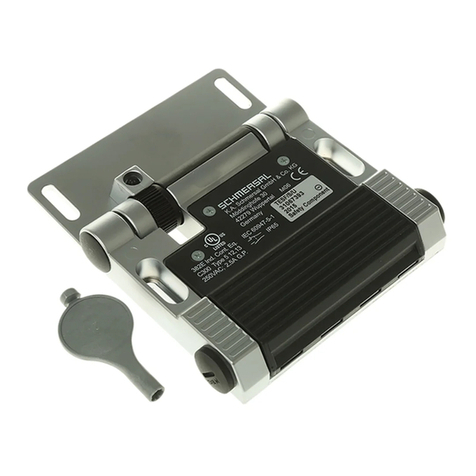
Hinge safety switch TESZ
EN
1.7 Exclusion of liability
We shall accept no liability for damages and malfunctions resulting from
defective mounting or failure to comply with this operating instructions
manual. The manufacturer shall accept no liability for damages result-
ing from the use of unauthorised spare parts or accessories.
For safety reasons, invasive work on the device as well as arbitrary re-
pairs, conversions and modifications to the device are strictly forbidden;
the manufacturer shall accept no liability for damages resulting from
such invasive work, arbitrary repairs, conversions and/or modifications
to the device.
2. Product description
2.1 Ordering code
This operating instructions manual applies to the following types:
TESZ
➀
➁
➂ ➃
/
➄
/
➅
/
➆
No. Option Description
➀
Aluminium hinge
X Stainless steel hinge
➁
R Mechanical restart interlock
➂
10 1 NC
102 1 NC / 1 NO
110 2 NC
1102 2 NC / 1 NO
1110 3 NC
➃
Screw connection
ST1 Connector bottom (M12, 8 pole)
ST2 Connector top (M12, 8 pole)
➄
With additional hinge
S Without additional hinge
➅
30 Fixing holes for 30 mm profile systems
35 Fixing holes for 35 mm profile systems
Fixing holes for 40 mm profile systems
45 Fixing holes for 45 mm profile systems
➆
Switching angle NC contact at 4 degrees
5° Switching angle NC contact at 5 degrees
8° Switching angle NC contact at 8 degrees
Not all component variants, which are possible according to this order
code, are available.
The types TESZR... mentioned below 2.1 as well as the
versions with ...ST1..., ...ST2... and ...5°, ...8° are not
included in the prototype test.
The mechanical reset of the TESZR... must not be used
as single start command for a hazardous movement.
2.2 Special versions
For special versions, which are not listed in the order code below 2.1,
these specifications apply accordingly, provided that they correspond to
the standard version.
2.3 Destination and use
The TESZ hinge safety switch has been designed to prevent, in con-
junction with the control part of a machine, movable safety guards from
being opened before hazardous conditions have been eliminated. They
are also suitable for fitting on profile sections and existing equipment.
Hinge safety switches can only be used for applications, in
which the hazardous condition is terminated without delay
(e.g. run-on movements) when the safety guard is opened.
The user must evaluate and design the safety chain in
accordance with the relevant standards and depending on
the required safety level.
The entire concept of the control system, in which the safety
component is integrated, must be validated to the relevant
standards.
2.4 Technical data
Standards: IEC 60947-5-1, BG-GS-ET-15
Enclosure: glass-fibre reinforced thermoplastic, self-extinguishing
Hinge: TESZ, aluminium /
TESZX stainless steel
Contact material: Silver
Protection class: IP65
Contact type: NC contact with double break Y
NO contact with double break X
Switching system:
A
IEC 60947-5-1 slow action,
NC contact with positive break
Connection: screw terminals or connector
Cable type: solid wire
Cable section: min. 0.5 mm², max. 0.75 mm²,
except TESZ..1102 and TESZ..1110
Cable type: solid and stranded wire
Cable section: min. 0.5 mm², max. 1.5 mm²
with conductor ferrules,
- TESZ..1102 and TESZ..1110: max. 1 mm² with conductor ferrules
Cable entry: 2 x M20
Positive break angle: 10°
Actuating speed: max. 135°/0.2 s
Actuating frequency: max. 120 operations/h
Mechanical life: > 1 million operations
TESZR..: 100,000 operations
Ambient temperature:
Utilisation category: AC-15, DC-13
Rated operating current/voltage Ie/Ue:
- with cable: 2 A / 230 VAC
1 A / 24 VDC
- with connector: 2 A / 24 VAC
1 A / 24 VDC
Rated insulation voltage Ui:250 V
- with connector: 36 V
Rated impulse withstand voltage Uimp:2.5 kV
- with connector: 0.8 kV
Thermal test current Ithe:2.5 A
Max. rated operating voltage Ue max.:230 VAC, 24 VDC
- with connector: 24 VAC
Max. fuse rating: 2 A gG D-fuse
Switching of low voltages: 1 mA / 5 VDC
UL: Listed 15 HA - Industrial Control Equipment -
Enclosure Type I - "Use Copper Wire Only" -
"Use 60 / 75° Wire Only" - Tightening Torque 0.8 Nm
The hub shall be connected to the conduit before
it is connected to the enclosure.
Only use as an end-of-line enclosure.
2.5 Safety classification
Standards: ISO 13849-1
Envisaged structure:
- Basically: applicable up to Cat. 1 / PL c
- With 2-channel usage and
fault exclusion mechanism*: applicable up to Cat. 3 / PL d
with suitable logic unit
B10d NC contact: 2,000,000
B10d NO contact at 10% ohmic contact load: 1,000,000
Service life: 20 years
* If a fault exclusion to the 1-channel mechanics is authorised.
