manuals.online logo
Brands
  1. Home
  2. •
  3. Brands
  4. •
  5. Omron
  6. •
  7. Switch
  8. •
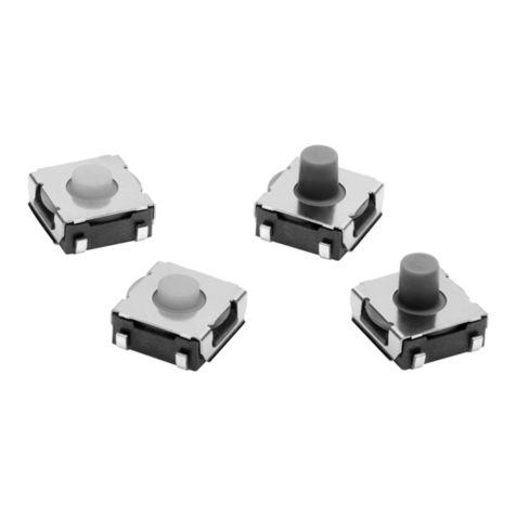
  9. Omron B3SN-3012 User manual

Omron B3SN-3012 User manual

This manual suits for next models

3

Other Omron Switch manuals

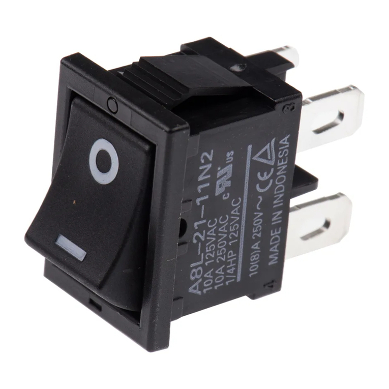
Omron A8L Installation instructions

Omron

Omron A8L Installation instructions
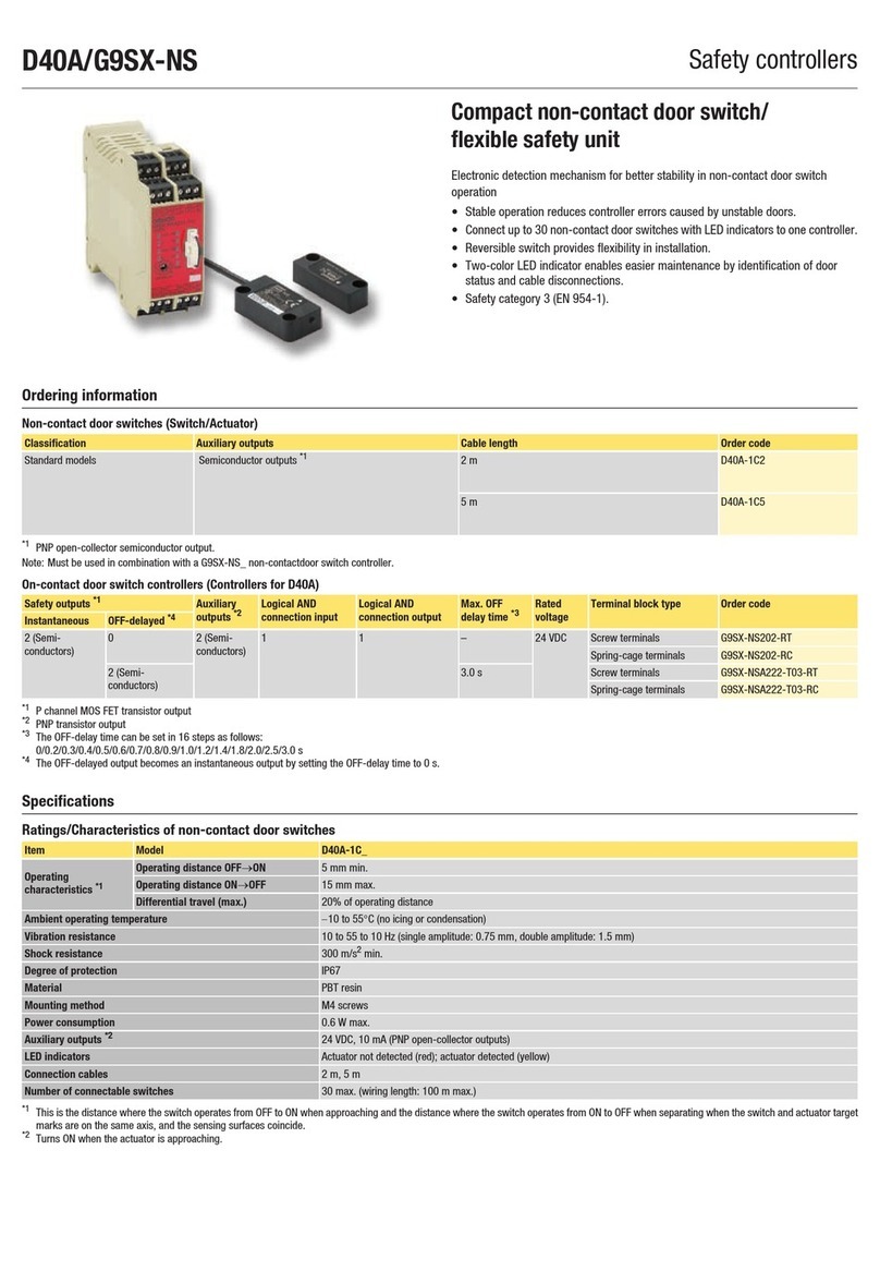
Omron D40A-G9SX-NS - User manual

Omron

Omron D40A-G9SX-NS - User manual
Omron H5S - User manual

Omron

Omron H5S - User manual

Omron A3A Series User manual

Omron

Omron A3A Series User manual

Omron DZ User manual

Omron

Omron DZ User manual

Omron D4BL - User manual

Omron

Omron D4BL - User manual

Omron H2F - User manual

Omron

Omron H2F - User manual

Omron A16 - User manual

Omron

Omron A16 - User manual

Omron A22TK User manual

Omron

Omron A22TK User manual

Omron XE - User manual

Omron

Omron XE - User manual

Omron A2W-R**-WC1 Series User manual

Omron

Omron A2W-R**-WC1 Series User manual

Omron A User manual

Omron

Omron A User manual

Omron HL-5030 User manual

Omron

Omron HL-5030 User manual

Omron D4NH - User manual

Omron

Omron D4NH - User manual

Omron A22NN User manual

Omron

Omron A22NN User manual

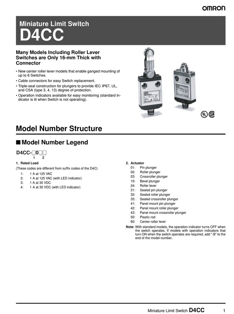
Omron D4CC-1001 User manual

Omron

Omron D4CC-1001 User manual

Omron A22E-MP User manual

Omron

Omron A22E-MP User manual
Omron SHL - User manual

Omron

Omron SHL - User manual

Omron D4BL - User manual

Omron

Omron D4BL - User manual

Omron D4A-N - User manual

Omron

Omron D4A-N - User manual

Omron A165S - User manual

Omron

Omron A165S - User manual

Omron D4DS User manual

Omron

Omron D4DS User manual

Omron Sti D40A User manual

Omron

Omron Sti D40A User manual

Omron A4E User manual

Omron

Omron A4E User manual

Popular Switch manuals by other brands

SMC Networks SMC6224M Technical specifications

SMC Networks

SMC Networks SMC6224M Technical specifications

Aeotec ZWA003-S operating manual

Aeotec

Aeotec ZWA003-S operating manual

TRENDnet TK-209i Quick installation guide

TRENDnet

TRENDnet TK-209i Quick installation guide

Planet FGSW-2022VHP user manual

Planet

Planet FGSW-2022VHP user manual

Avocent AutoView 2000  AV2000BC AV2000BC Installer/user guide

Avocent

Avocent AutoView 2000 AV2000BC AV2000BC Installer/user guide

Moxa Technologies PT-7728 Series user manual

Moxa Technologies

Moxa Technologies PT-7728 Series user manual

Intos Electronic inLine 35392I operating instructions

Intos Electronic

Intos Electronic inLine 35392I operating instructions

Cisco Catalyst 3560-X-24T Technical specifications

Cisco

Cisco Catalyst 3560-X-24T Technical specifications

Asante IntraCore IC3648 Specifications

Asante

Asante IntraCore IC3648 Specifications

Siemens SIRIUS 3SE7310-1AE Series Original operating instructions

Siemens

Siemens SIRIUS 3SE7310-1AE Series Original operating instructions

Edge-Core DCS520 quick start guide

Edge-Core

Edge-Core DCS520 quick start guide

RGBLE S00203 user manual

RGBLE

RGBLE S00203 user manual

Thrustmaster FLIGHT SIMULATOR X quick guide

Thrustmaster

Thrustmaster FLIGHT SIMULATOR X quick guide

Southwire SURGE GUARD 41390 RVC troubleshooting guide

Southwire

Southwire SURGE GUARD 41390 RVC troubleshooting guide

Buhler Nivotemp NT 61 Brief instructions

Buhler

Buhler Nivotemp NT 61 Brief instructions

Kramer VS-41HDCP user manual

Kramer

Kramer VS-41HDCP user manual

Techly IDATA AU-270 user manual

Techly

Techly IDATA AU-270 user manual

Belkin F1U109 user manual

Belkin

Belkin F1U109 user manual

manuals.online logo
manuals.online logoBrands
  • About & Mission
  • Contact us
  • Privacy Policy
  • Terms and Conditions

Copyright 2025 Manuals.Online. All Rights Reserved.

1
Tactile Switch (Sealed SMD Type) B3SN
Designed as Surface-mounting Device
(SMD) Meeting High-density Mounting
Requirements
SMD
T
actile Switch ideal for high-density mounting.
Compact and more than 1 mm thinner than
conventional tactile switches.
Available with ground terminals for protection
against static electricity.
Sealed construction conforming to IP64 (IEC-529)
provides high reliability in dusty or humid
environments.
Ordering Information
Model Number Legend:
B3SN-jjjjj
12345
1. Height
3: 3.1
mm
2. Ground terminal
0:
Without ground terminal
1:
With ground terminal
3. Sealing
1:
IP64 (IEC529)
4. Operating force (OF)
2:
1.57 N {160 gf}
5.
Shipment package
None: Bag
P:
Embossed tape
List of Models
Type Bags Embossed
tape (see note)
W
ithout ground terminal
B3SN-3012 B3SN-3012P
W
ith ground terminal
B3SN-3112 B3SN-3112P
Note:
Switches on embossed tape must be ordered in units of 3,000 pieces.
For details on packing, refer to
Switch Pacing
on page
17.
Specifications
Ratings/Characteristics
Switching
capacity
1 to 30 mA, 5 to 24 VDC (resistive load)
Contact configuration
SPST-NO
Contact resistance
100 m
Ω
max. (initial value) (rated: 1 mA, 5 VDC)
Insulation resistance
100 M
Ω
min. (at 250 VDC)
Dielectric strength
250 V
AC, 50/60 Hz for 1 min
Bounce time
5 ms max.
V
ibration resistance
Malfunction: 10 to 55 Hz, 1.5-mm double amplitude
Shock resistance
Destruction: 1,000 m/s
2
{approx. 100G} max.
Life expectancy
100,000 operations min.
Ambient temperature
Operating: –25
°
C to 70
°
C (with no icing)
Ambient humidity
Operating: 35% to 85%
Weight
Approx. 0.2 g
B3SN B3SN
2
Engineering Data
Operating Force vs. Stroke (Typical)
Stroke
S (mm)
Operating force (N {gf})
1.96 {200}
1.47 {150}
0.98 {100}
0.49 {50}
Nomenclature Film
Push
button
Cover
Terminals
Plunger
Contact dome
Fixed contact
Base
B3SN B3SN
3
Dimensions
Note: 1.
All units are in millimeters unless otherwise indicated.
2. No
terminal numbers are indicated on
the Switches. The numbers used for terminals in the following graphics are indicated in the
“Bottom
V
iew” diagram below
. In this diagram, the Switch is rotated so that the terminals
are on the right and left-hand sides, and the
OMRON
logo appears the right way up.
(Bottom V
iew)
3
1
4
2
Without Ground Terminal
B3SN-3012
B3SN-3012P
With Ground Terminal
B3SN-3112
B3SN-3112P
PCB
Mounting
(T
op V
iew) T
erminal Arrangement
/Internal Connections
(T
op V
iew)
2
4
1
3
9.5
4
2.6 5.4
2
6
3 dia.
1.2 0.7
6.5
(4.6)
7±0.5
4±0.2
2
4
1
3
5
9.5
4
2.6 5.4
1.4
3 dia.
6
(4.6)
1.2
2
6.5
0.70.7
7±0.5
4±0.2
3.4±0.2
PCB
Mounting
(T
op V
iew) T
erminal Arrangement
/Internal Connections
(T
op V
iew)
3.1+0.3
0
3.1+0.3
0
0.1
Operating Characteristics
Operating force (OF) 1.57±
0.49 N {160
±
50 gf} max.
Releasing force (RF)
0.29 N {30 gf} min.
Pretravel (PT) 0.25±
0.15 mm
Precautions
Soldering
Do
not apply flow
soldering, otherwise fragments of solder and flux
may
have a bad influence on the operation of the pushbutton.
Apply reflow soldering according to the optimum heating curve
shown below. Reflow soldering equipment may have a high peak
value.
Be sure to conduct a test before use.
Soldering
may be
repeated only once at a minimum interval of five
minutes
if the Switch is not soldered properly
.
Note: The above heating curve applies if the
thickness
of the circuit board is 1.6 mm.
T
emperature ( C)
°
Room
temperature
T
ime (s)
60
to 90 s
20 max.
10 max.
Preheating
B3SN B3SN
4
Do not apply additional force to the plunger once it has stopped
moving.
Do not repeatedly press the plunger off-center or from an acute
angle.
Cleaning
B3SN
Switches are designed to allow submersed cleaning after sol
-
dering.
When cleaning, follow the guidelines given as follows:
1. Clean
with alcohol solvents. Do not use chlorine solvents
or
water.
2. When using ultrasonic cleaning in two- or three-tank
systems,
do not clean for more than one minute at a time or for
more
than three minutes total.
3.
Do not apply external force to the Switch while cleaning.
4. Do
not clean immediately after
soldering. Allow components
to
stand for at least three minutes before
cleaning if possible.
5. The Switch cannot be used where subject to direct contact
with
water
.
Switch Packing
Switches
are packed on tape as shown below
.
(18) Label Tape drawing direction
Reel
Tape drawing direction
2
5.5
(3.6)
13 dia. 380±2 dia.
1.75±0.1
8±0.1
4±0.1
12±0.3
1.5+0.1
0 dia.
Package 3,000 Switches
Heat resistance
50°
C for 24 hours (not to be deformed)
Note: The
ground terminals of the Switches are on the guide hole
side
of the package.
ALL DIMENSIONS SHOWN ARE IN MILLIMETERS.
To
convert millimeters into inches, multiply by 0.03937. T
o convert grams into ounces, multiply by 0.03527.
Cat. No. C096-E1-2A