Schulte-Schlagbaum SAFE-O-TRONIC access LS101 User manual

Manual
SAFE-O-TRONIC®access
LS101 / LSW101
Cabinet Lock
English
D&E Architectural Hardware Ltd
17 Royce Road, Carr Road Ind. Est.
Peterborough, Cambs. PE1 5YB
www.DandE.co.uk

Manual LS101 / LSW101
Schulte-Schlagbaum AG Page 2 of 39 LS(W)101_6-703-2 30R1 4_EN.DOCX
Information about this guide
Copyright 2018 by Schulte-Schlagbaum AG
Nevigeser Straße 100-110
42553 Velbert, Germany
Phone: +49 2051 2086-0
http:/www.sag-schlagbaum.com
Edition: 20190607
Version: 1.4
Document number: LS(W)101_6-703-2 30R1 4_EN
This edition renders invalid all previous editions.
Information in this document can be changed without prior announcement.
Dissemination and duplication of this document, and use and disclosure of its contents, are
prohibited unless expressly permitted. Violations will incur compensation for damage. All
rights created by patent grant or registration of a utility model or design are reserved.
The information in this document has been compiled in good faith and to the best of our knowledge.
Schulte-Schlagbaum AG extends no guarantee for the correctness or completeness of information
in this document. In particular, Schulte-Schlagbaum AG cannot be held liable for consequential
damage due to erroneous or incomplete information. Mistakes can never be prevented entirely
despite all the effort taken, and so we appreciate when mistakes are pointed out to us.
SAFE-O-TRONIC®is a registered trademark of Schulte-Schlagbaum AG.
Safety information and warnings
This guide describes commissioning and operation of a SAFE-O-TRONIC®access
LS(W)101 furniture lock.
The device may only be used for the purpose intended by the manufacturer.
This guide must be kept in an easily accessible location.
Unauthorised modifications and the use of spare parts and auxiliary devices that are not sold
or recommended by the manufacturer may result in fire, electric shock and injury. Actions
such as these result in exclusion of liability, and no warranty claims will be accepted by the
manufacturer.
Repairs may only be carried out by the manufacturer.
The warranty provisions of the manufacturer as amended on the date of purchase apply to
the device. Liability will not be assumed for inappropriate manual and automatic creation of
parameters for a device or inappropriate use of a device.
The operating company is responsible for setting up and connecting the device according to
recognised technical regulations in the country of installation and other valid provisions.

Manual LS101 / LSW101
Schulte-Schlagbaum AG Page 3 of 39 LS(W)101_6-703-2 30R1 4_EN.DOCX
Content
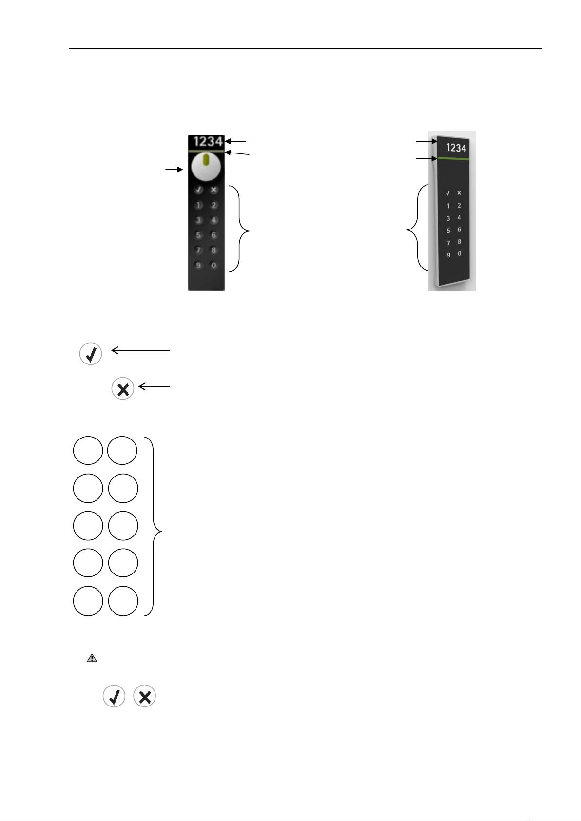
Controls............................................................................................................................................................... 4
General information ........................................................................................................................................... 5
Capacitive keypad...........................................................................................................................................5
Protection against tampering........................................................................................................................... 5
Information about this guide............................................................................................................................5
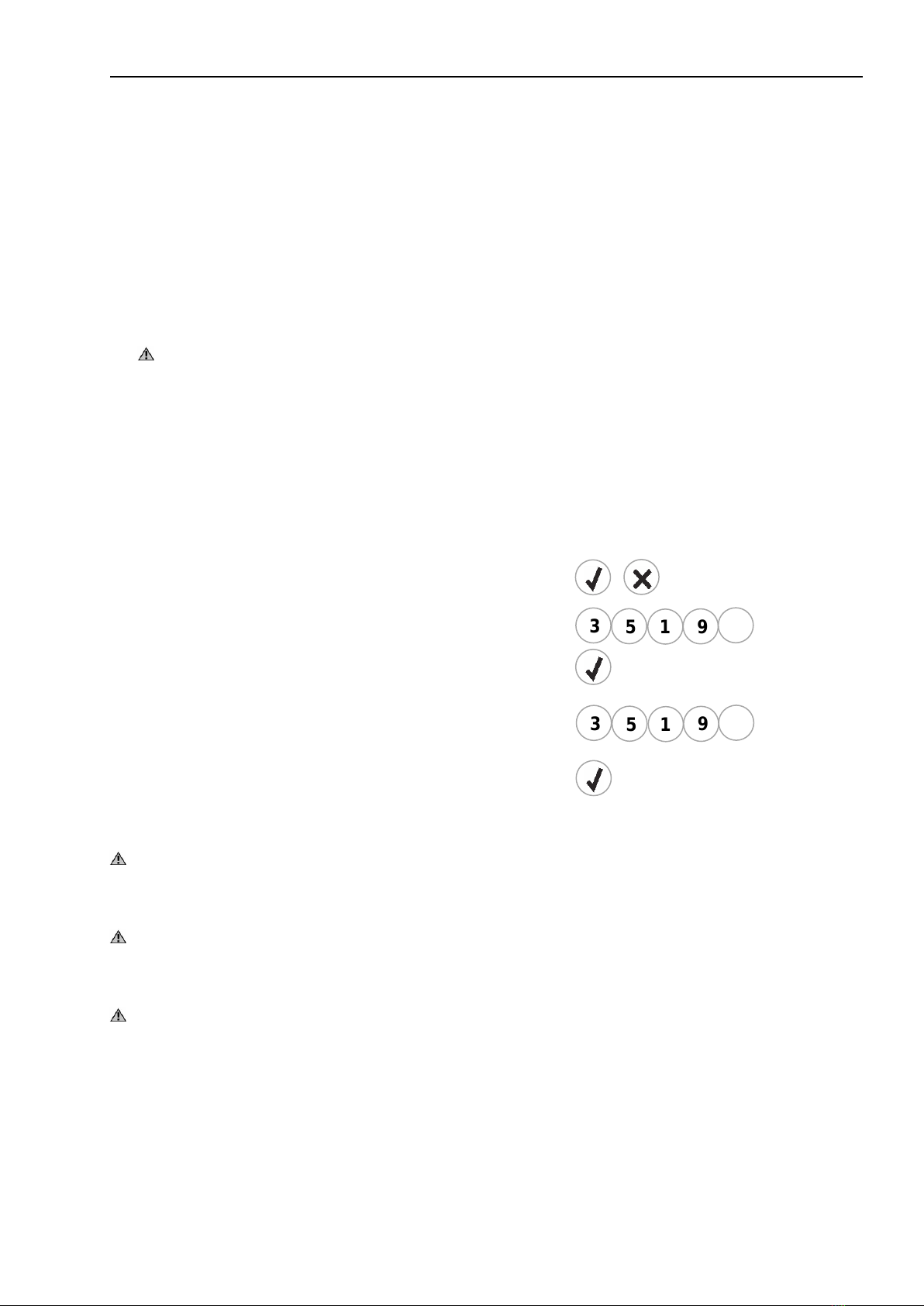
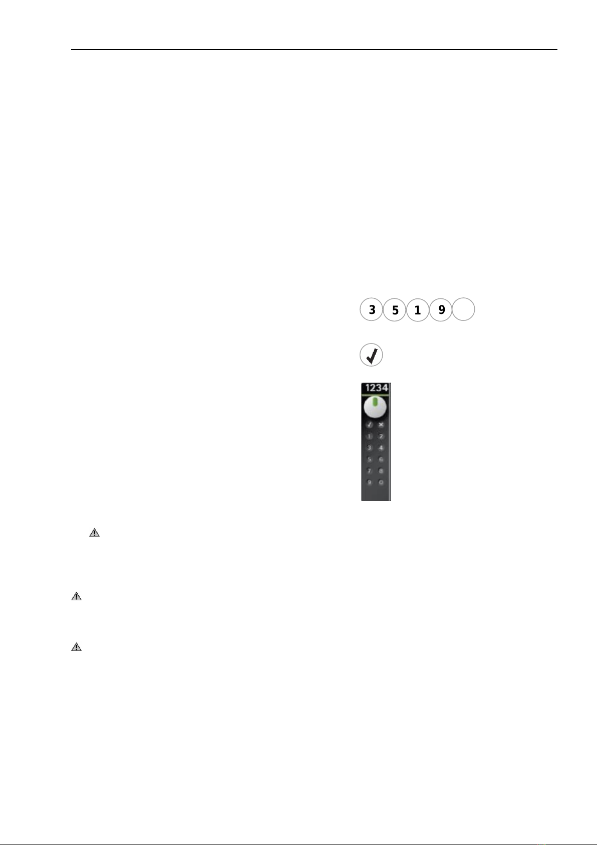
Test Code........................................................................................................................................................ 6
Commissioning................................................................................................................................................... 7
Initially programming the Master Code ...........................................................................................................7
Master Code........................................................................................................................................................8
Locking and unlocking using the Master Code ...............................................................................................8
Changing the Master Code .............................................................................................................................9
Master Code guidelines...................................................................................................................................9
Modes ................................................................................................................................................................ 10
Mode overview ..............................................................................................................................................11
Changing the mode.......................................................................................................................................12
Mode examples.............................................................................................................................................13
Fixed cabinet assignment................................................................................................................................15
One open.......................................................................................................................................................15
All open..........................................................................................................................................................15
Entering the User PIN ...................................................................................................................................16
Deleting a User PIN.......................................................................................................................................17
Usage duration .................................................................................................................................................18
Time unit overview ........................................................................................................................................18
Usage duration overview...............................................................................................................................18
Changing the usage duration........................................................................................................................19
LS(W)101 functions..........................................................................................................................................20
LS(W)101 overview of settings......................................................................................................................20
Changing the LS(W)101 settings ..................................................................................................................21
Information........................................................................................................................................................22
LED display ...................................................................................................................................................22
Troubleshooting.............................................................................................................................................23
Battery replacement......................................................................................................................................... 23
Battery monitoring / Battery alarm.................................................................................................................24
LS101 installation.............................................................................................................................................25
Installation direction.......................................................................................................................................25
LS101 installation notes ................................................................................................................................26
Preparing the door for LS101 installation......................................................................................................27
Installation .....................................................................................................................................................27
Setting the direction of rotation for the LS101...............................................................................................28
LS101 dimensions.........................................................................................................................................29
Technical data...............................................................................................................................................29
LSW101 installation..........................................................................................................................................30
Installation of outer housing ..........................................................................................................................30
LSW101 –installation of inner housing.........................................................................................................31
LSW101 sensing slide...................................................................................................................................32
Installation instructions for the LSW101........................................................................................................33
LSW101 dimensions .....................................................................................................................................34
LSW101 technical data .................................................................................................................................35
Maintenance and care......................................................................................................................................36
Identification plate replacement .....................................................................................................................36
Appendix ...........................................................................................................................................................37
Intended use ..................................................................................................................................................... 39

Manual LS101 / LSW101
Schulte-Schlagbaum AG Page 4 of 39 LS(W)101_6-703-2 30R1 4_EN.DOCX
Controls
OK key: Completion of a PIN code input
Abort key: Pressing the Abort key clears the PIN Code input
and aborts the current process.
Keys 1, 2, 3, 4, 5, 6, 7, 8, 9, 0: Number keys for PIN code entry
Note
Programming is initiated with the following key combination:
= Press the OK and Abort keys at the same time
1
2
3
4
5
6
7
8
9
0
LED display
Replaceable identification plate
Rotary knob
Capacitive keypad
&
LS101
LSW101

Manual LS101 / LSW101
Schulte-Schlagbaum AG Page 5 of 39 LS(W)101_6-703-2 30R1 4_EN.DOCX
General information
Capacitive keypad
The SAFE-O-TRONIC®access LS(W)101 furniture locking system uses a capacitive keypad for
entering PIN codes. Unlike a mechanical keypad, the capacitive keypad does not require any
pressure or force. All you have to do is tap the keys.
Note: This capacitive keypad cannot be operated with gloves.
Operator guidance
Operation is supported by the red / green LED display as well as an acoustic signal by means of a
beeper.
Information on keypad input
In the event of a pause of more than three seconds between pressing of individual keys, the entire
entry is cancelled.
Protection against tampering
Level 1:
The user has a maximum of five tries to enter the right PIN code. After the fifth incorrect entry, every
further entry is blocked for one minute to ensure tampering protection.
This block time of one minute is indicated by the red LED flashing.
Level 2:
After a total of 50 incorrect entries the LS(W)101 is blocked. Users are then unable to enter PIN
codes.
This tampering block can only be lifted with your Master Code.
Information about this guide
The furniture locking system can be locked.
LS101 = Rotary knob
LSW101 = Motorised bolt
The furniture locking system can be unlocked.
LS101 = Rotary knob
LSW101 = Motorised bolt

Manual LS101 / LSW101
Schulte-Schlagbaum AG Page 6 of 39 LS(W)101_6-703-2 30R1 4_EN.DOCX
Function check
All SAFE-O-TRONIC®access LS(W)101 furniture locking systems are supplied with the same
factory setting. In the factory setting, only the Test Code for locking and unlocking is active.
Test Code
You can use the Test Code to perform a simple function check of the SAFE-O-TRONIC®access
LS(W)101. Once installed, test the locking function of the SAFE-O-TRONIC®access LS(W)101
using the Test Code.
In particular, ensure ease of movement of the lever (or bolt) during locking and unlocking.
Installation under tension can result in malfunction.
Locking and unlocking using the Test Code
►Press the 0key
►Then press the OK key
►The rotary knob can be actuated for locking
Locking and unlocking using the Test Code
►Press the 0key
►Then press the OK key
►The motorised bolt locks automatically
0
0
LS101
LSW101

Manual LS101 / LSW101
Schulte-Schlagbaum AG Page 7 of 39 LS(W)101_6-703-2 30R1 4_EN.DOCX
Commissioning
Initially programming the Master Code
Every SAFE-O-TRONIC® access LS(W)101 can be programmed for commissioning using its
Master Code. The Master Code (5-9 digits) can be freely selected. The Master Code can only be
programmed when the LS(W)101 is unlocked.
Once you have programmed your Master Code, the LS(W)101 can be operated or configured
further.
Note
Please ensure that unauthorised persons do not obtain the programmed Master Code!
You can change the Master Code at any time.
Master Code cannot be programmed using a leading 0!
Programming the Master Code in factory setting
► Press the OK and Abort key at the same time
► Enter your Master Code
► Press the OK key
► Enter your Master Code again for verification
►Press the OK key to complete the process
Note
After programming the Master Code, mode 147 is automatically activated. More information
on the modes is described in the following sections.
Note
This guide only uses example PIN codes.
Please always use your own PIN codes for your locking system.
Note
After successfully programming your Master Code, the Test Code is automatically disabled
and can no longer be used for locking.
&
1
3
5
7
9
1
3
5
7
9

Manual LS101 / LSW101
Schulte-Schlagbaum AG Page 8 of 39 LS(W)101_6-703-2 30R1 4_EN.DOCX
Master Code
The system operator can use the Master Code at any time* to open and close the LS(W)101.
*In modes 1x8, 4x8 and 4x9 the Master Code cannot be used for locking.
Locking and unlocking using the Master Code
If a Master Code has been programmed, the LS(W)101 can be unlocked or locked with the active
Master Code at any time.
Example: LS101:
► Enter the active Master Code
► Then press the OK key
► Turn the rotary knob
Note
If an unlocked LS(W)101 is locked with a Master Code, this LS(W)101 can then only be
unlocked with the Master Code. In modes 1x8, 4x8 and 4x9 the Master Code cannot be used
for locking.
Note
This guide only uses example PIN codes.
Please use your own PIN codes for your locking system.
Note
Please ensure that unauthorised persons do not obtain your programmed Master Code!
1
3
5
7
9

Manual LS101 / LSW101
Schulte-Schlagbaum AG Page 9 of 39 LS(W)101_6-703-2 30R1 4_EN.DOCX
Changing the Master Code
If your Master Code has wound up in unauthorised hands, you should change the Master Code
straight away.
It is also possible to use different Master Codes for different areas in your locking system. As a
result, one master code can be used to set parent locking permissions.
►Press the OK and Abort keys at the same time
►Enter the active Master Code
►Press the OK and Abort keys at the same time
►Enter a new Master Code
►Press the OK key
►Enter the new Master Code again
►Press the OK key
Note
This guide only uses example PIN codes.
Please use your own PIN codes for your locking system.
Note
If you have forgotten the Master Code, a Master Reset is required. In this case, please
contact our support.
Master Code guidelines
You can choose any Master Code for your system. The following Master Code guidelines must be
followed:
At least 5 digits
Minimum ‘User PIN length’ +1
Maximum of 9 digits
Always complete your Master Code input by pressing the OK key
&
1
3
5
7
9
&
2
3
4
7
8
2
3
4
7
8

Manual LS101 / LSW101
Schulte-Schlagbaum AG Page 10 of 39 LS(W)101_6-703-2 30R1 4_EN.DOCX
Modes
The LS100 and LSW101 pin code locking systems offer different modes so you can custom-
configure your locking system according to your needs.
To better understand the configuration options for different modes, the following sections briefly
present various configuration options.
Free cabinet choice (free)
The LS(W)101 locking system is configured so that a user can freely choose a cabinet and a PIN to
lock the cabinet.
Fixed cabinet assignment (fix)
The LS(W)101 locking system is configured so that a user is assigned a cabinet as well as a PIN to
lock the cabinet by the system operator. With fixed cabinet assignment, up to ten different user PINs
can be programmed.
OK key
To confirm the entered user PIN, there are modes with or without OK key to lock or
unlock a cabinet.
Number of digits for the User PIN
The User PIN code can have 4, 5 or 6 digits and can be selected freely for each mode.
Note
Please note the Master Code guidelines when selecting your mode.
Examples:
4-digit User PIN > Master Code min. 5 digits, max. 9 digits
5-digit User PIN > Master Code min. 6 digits, max. 9 digits
6-digit User PIN > Master Code min. 7 digits, max. 9 digits

Manual LS101 / LSW101
Schulte-Schlagbaum AG Page 11 of 39 LS(W)101_6-703-2 30R1 4_EN.DOCX
Mode overview
The permitted mode settings are listed in the table below.
The mode can only be set once a Master Code has been programmed.
When setting modes, only the 3-digit PIN code listed below is permitted. The mode can only be set
when the lock is unlocked.
The next section provides examples on entering modes.
Note
After initially programming the furniture locking system, mode 147. (free cabinet selection, 4-
digit, with OK key) is set by default.
Free
(free)
Fixed
(fix)
User
PIN
length
One
open
All
open
Description
PIN Code to
set the mode
4
5
6
X
X
X
With OK key
1
X
7
X
X
X
Without OK key
1
X
8
X
X
X
Lock with OK key
1
X
9
X
X
X
With OK key
2
X
7
X
X
X
Without OK key
2
X
8
X
X
X
Lock with OK key
2
X
9
X
X
X
With OK key
3
X
7
X
X
X
Without OK key
3
X
8
X
X
X
Lock with OK key
3
X
9
X
X
X
Lock without PIN (only LS101)
4
X
8
X
X
X
Lock with OK key (without pin)
4
X
9

Manual LS101 / LSW101
Schulte-Schlagbaum AG Page 12 of 39 LS(W)101_6-703-2 30R1 4_EN.DOCX
Changing the mode
You can change the mode for your furniture locking system at any time. A new mode can only be
entered when the lock is unlocked.
The following describes how to enter a new mode.
Example: Mode 148
► Press the OK and Abort keys at the same time
► Enter the active Master Code
► Press the OK and Abort keys at the same time
► Enter new mode
► Press the OK key
► Enter new mode again
► Press the OK key
Note
The mode can only be changed when the lock is unlocked.
When changing the mode, all User PINs entered in fixed cabinet assignment modes are
deleted.
&
1
3
5
7
9
&
4
8
1
4
8
1

Manual LS101 / LSW101
Schulte-Schlagbaum AG Page 13 of 39 LS(W)101_6-703-2 30R1 4_EN.DOCX
Mode examples
The following examples present several modes. The length of the PIN code (4, 5 or 6 digit) depends
on the selected mode.
Mode: 147
Free cabinet selection, 4-digit PIN with OK key
Enter 4-digit PIN
Press the OK key
Enter 4-digit PIN
Press the OK key
Mode: 268
Fixed cabinet assignment, 6-digit PIN without OK key, one open
Enter 6-digit PIN
Enter 6-digit PIN
1
3
5
5
1
3
5
5
1
3
5
5
1
3
5
5
1
5
1
5

Manual LS101 / LSW101
Schulte-Schlagbaum AG Page 14 of 39 LS(W)101_6-703-2 30R1 4_EN.DOCX
Mode: 459
Fixed cabinet assignment, 5-digit PIN, lock only with OK key, all open
Press the OK key
Enter 5-digit PIN
Mode: 448
Fixed cabinet assignment, 4-digit PIN, lock without OK key, all open
This mode can only be used with the LS101 variant.
Turn knob to lock position
Enter 4-digit PIN
Note
This guide only uses example codes.
Please use your own PIN codes for your locking system.
Note
The mode can only be changed when the lock is unlocked.
1
3
5
7
3
1
3
5
7

Manual LS101 / LSW101
Schulte-Schlagbaum AG Page 15 of 39 LS(W)101_6-703-2 30R1 4_EN.DOCX
Fixed cabinet assignment
One open
In fixed cabinet assignment mode, you can configure which users are permitted to unlock the locked
cabinet. In the ‘one open’ setting, only the user who locked the cabinet can unlock it.
All open
In fixed cabinet assignment mode, you can configure which users are permitted to unlock the locked
cabinet. In the ‘all open’ setting, all programmed users can unlock the locked cabinet, no matter who
locked it.

Manual LS101 / LSW101
Schulte-Schlagbaum AG Page 16 of 39 LS(W)101_6-703-2 30R1 4_EN.DOCX
Entering the User PIN
With its fixed cabinet assignment mode, the LS(W)101 locking system offers the option to program
up to ten different User PINS per lock. Depending on the mode, you can program 4-, 5- or 6-digit
User PINS. The User PINs only have to be entered once during programming.
The following describes how to enter the User PINS.
Example: Mode 247, fixed cabinet assignment, four-digit with OK key, one open.
Enter three User PINs –7458, 8488 and 1181
►Press the OK and Abort keys at the same time
►Enter the active Master Code
►Press the OK and Abort keys at the same time
►Enter the User PIN
►Press the OK key
►Enter the User PIN
►Press the OK key
►Enter the User PIN
►Press the OK key
Note
User PINs can only be entered when the lock is unlocked.
After entering the last User PIN, you can finish by pressing the Abort key.
You can add further User PINs to your specified User PINs at any time.
You can enter a maximum of ten User PINs per lock.
&
1
3
5
7
9
&
4
8
4
8
8
8
1
7
5
8
1
1

Manual LS101 / LSW101
Schulte-Schlagbaum AG Page 17 of 39 LS(W)101_6-703-2 30R1 4_EN.DOCX
Deleting a User PIN
To delete entered User PINs from your lock, you have to enter a delete PIN. All User PINs in the
lock are then deleted. It is not possible to delete individual User PINs from the lock.
The following describes how to delete all User PINS.
Example: Deleting all User PINs
► Press the OK and Abort keys at the same time
► Enter the active Master Code
► Press the OK and Abort keys at the same time
► Enter the delete PIN
► Press the OK key
► Enter the delete PIN again
► Press the OK key
Note
All User PINs in your lock are deleted.
Afterwards, you can enter up to ten different new User PINs for the lock.
&
1
3
5
7
9
&
0
0
0
0
0
0
0
0

Manual LS101 / LSW101
Schulte-Schlagbaum AG Page 18 of 39 LS(W)101_6-703-2 30R1 4_EN.DOCX
Usage duration
The LS(W)101 locking system offers the option to restrict the usage duration. This enables you to
easily prevent unauthorised cabinet reservations in your system.
To better understand the configuration options for setting the duration of use, the following sections
briefly present various configuration options.
Usage duration with automatic lock unlocking
At the end of the usage duration, the lock automatically unlocks after a configurable amount of time.
After the cabinet is opened, you have to enter a new PIN to use it again (depending on the mode).
Usage duration with automatic lock blocking
At the end of the usage duration, the lock is automatically blocked after a configurable amount of
time. When blocked, the cabinet can only be unlocked using the active Master Code. After the
cabinet is opened using the Master Code, you have to enter a new PIN to use it again (depending
on the mode).
Setting the usage duration
The usage duration starts after the lock is locked. The usage duration can be configured from one
time unit up to 99 time units. The usage duration function is disabled by default and the hour is set
as time unit.
Time unit overview
The available time unit settings are listed in the table below. The time unit can be changed as
described in chapter “Changing the LS(W)101 settings”.
Usage duration overview
The available duration usage settings are listed in the table below.
The usage duration can be set from 0-99 time units.
Note
The default setting after initial programming is the usage duration 700.
The default setting after initial programming is the time unit hour 950.
Used time unit
PIN Code to set
the time unit
Hour
9
5
0
Minute
9
5
1
Second
9
5
2
Unlock
Block
Duration
in hours
XX
Description
PIN Code to set
the usage
duration
-
-
00
No usage duration
7
0
0
01-99
After the usage duration ends: Unlock
7
X
X
01-99
After the usage duration ends: Block
8
X
X

Manual LS101 / LSW101
Schulte-Schlagbaum AG Page 19 of 39 LS(W)101_6-703-2 30R1 4_EN.DOCX
Changing the usage duration
You can change the usage duration for your locking system at any time. A new usage duration can
only be entered when the lock is unlocked.
The following describes how to enter a new usage duration.
Example: Usage duration 705: The lock unlocks automatically after 5 time units
►Press the OK and Abort keys at the same time
►Enter the active Master Code
►Press the OK and Abort keys at the same time
►Enter a new usage duration
►Press the OK key
►Enter the new usage duration again
►Press the OK key
Note
The usage duration can only be changed when the lock is unlocked.
&
1
3
5
7
9
&
0
5
0
5
7
7

Manual LS101 / LSW101
Schulte-Schlagbaum AG Page 20 of 39 LS(W)101_6-703-2 30R1 4_EN.DOCX
LS(W)101 functions
The LS(W)101 locking system also offers different options for configuring special functions. These
functions can be enabled for the LSW101 locking system.
With these LSW101 functions, you can customise your locking system to your needs, but also to
different cabinet versions.
To better understand the configuration options for selecting the various LSW101 functions, the
following sections briefly present various functions.
LED status
You can set a flashing red LED on the LSW101 locking system to indicate that the cabinet is
‘locked’. This setting slightly increases the energy consumption of the LSW101 locking system.
Querying the door status
The LSW101 locking system is equipped with a door recognition sensor system. This sensor system
detects whether the door is open or closed. In unsuitable cabinet constructions, the sensor system
can cause malfunctions. In such cases, the door recognition query can be disabled. When the door
recognition query is disabled, the alarm function is no longer available.
Alarm
In combination with the door status query for locked cabinets, it is possible to emit an alarm signal in
case of unauthorised break-in. The alarm signal (LED flashing and signal sound) ends automatically
after one minute.
Buzzer
The buzzer can be disabled as needed. This function can also be used for the LS101 locking
system.
LS(W)101 overview of settings
The different LSW101 settings are listed in the table below. You can change these settings at any
time.
Note
The LSW default settings following initial programming are:
910 (LED off); 920 (query off); 930 (alarm off); 941 (buzzer on)
Description
off
on
LS101
LSW101
PIN Code to set the LS(W)101
LED status: without LED signal
9
1
0
LED status: with LED signal
9
1
1
Door status query: off
9
2
0
Door status query: on
9
2
1
Alarm: off
9
3
0
Alarm: on
9
3
1
Buzzer: off
9
4
0
Buzzer: on
9
4
1
This manual suits for next models
1
Table of contents
Popular Door Lock manuals by other brands

Signature Hardware
Signature Hardware AMBRUS 951089-KE manual

Eurospec
Eurospec Push Bar Panic Bolt installation instructions

Assa Abloy
Assa Abloy multi-t-lock Code Handle Window manual

Weiser
Weiser 44578 instructions

Hewi
Hewi matt 111PBDG02 Mounting instructions

CEStronics
CEStronics RF-Master-Set Fitting and operating instructions