Scion-Tech SC08.MX2000 User manual

SC08.MX2000
User Manual
Version 1.0
Network HDMI Matrix Switching (SDVoE)
18Gbps, 4K/60Hz, 4:4:4, HDR
User Manual
Scion Tech
SC08.MX2000
Tel: +44 (0) 1635 862484 www.scion-tech.co.uk

User Manual
Scion Tech
SC08.MX2000
Thank you for purchasing this product
For optimum performance and safety, please read these instructions carefully before connecting,
operating or adjusting this product. Please keep this manual for future reference.
Surge protection device recommended
This product contains sensitive electrical components that may be damaged by electrical spikes, surges,
electric shock, lighting strikes, etc. Use of surge protection systems is highly recommended in order to
protect and extend the life of your equipment.
Table of Contents
1. Introduction…………………………………………………….…………………………….…….…………….……………………….
2. Features……………………………………………………………………………………………………….……….…………….……..
3. Package Contents…………………………………….……………………………………………………………….……….………..
4. Specifications…………………………………………………………………….………………………………………………….……
5. Panel Description Encoder (Transmitter)………………….…..….……………….…….………………………….……….
6. Panel Description Decoder (Receiver)..….…….….……………….…………………………….………….…….…………..
7. Installing the Encoder (Transmitter)….……………….…….…….…..…………….………….….………………………….
8. Installing the Decoder (Receiver)…………………………………………….…………….……….……………………………
9. IR Cable Wiring……………………….….…………………………………………………….………………………….……………..
10. Recommended Network Switches…………….……………………………………….………………….……….…………..
11. Network IGMP Snooping and Querier Explained…….………………………………………………………….……….
12. Application Drawing……………………………….……………………………………….……………….……………………….
13. Maintenance and Warranty…………………………………….…….….………………………….………….….……………
3
3
3
4
5
6
7
8
9
10
10
12
13
Tel: +44 (0) 1635 862484 www.scion-tech.co.uk
Page 2
Note:
For software installation and control, see SC08.CTL200 Network Controller documents.

1. Introduction
The SC08.MX2000 is an over IP solution for high definition signal extension over copper cables. This 4K
solution leverages 10 Gb Ethernet switches and enables signal management of 4K/60Hz (4:4:4) signals
with zero frame latency. Bi-Directional RS232, Infra-Red, 1 Gb LAN, and embedded audio are also
supported.
The video wall mode allows a single video source to be stretched across multiple displays, each receiver
crops and scales the region of interest according to its position in the wall matrix. The receivers are
locked to the source and thus to each other with no frame rate conversion.
When used in multiview mode the MX2000 routes multiple independent sources from transmitters to a
single receiver, who then composites them into a single output. The sources can be different resolutions
and frames rates. Multiview adjusts and scales various source signals, placing them in a predefined
layout of specific dimension, then composites the scene and generates a video signal of specified
resolution and frame rate.
The SC08.MX2000 is managed and controlled using RS232 and IP control codes over the network using
an integrated web browser, PC Windows™ application or from virtually any third party controller,
including those from AMX, Crestron, Control4.
2. Features
●Create bespoke size matrix using transmitters, receivers and 10G network switches
●Resolution: 4K/60Hz, RGB/YCbCr 4:4:4, YCbCr 4:2:2, YUV 4:2:0
●Standards: HDMI 2.0, HDCP 2.2, HDR
●Uncompressed zero frame latency
●Audio: LPCM, Dolby Digital™, DTS Surround Sound
●Full Duplex RS232 pass-through
●Bi-Directional IR
●HDMI or Display Port inputs
●RS232 and IP control
3. Package contents
Transmitter
1. 1 x Main Unit (SC08.MX2000-T)
2. 1 x IR Blaster Cable with 2 Pin Phoenix
3. 1 x IR Receiver Cable with 3 Pin Phoenix
4. 1 x DC 12V/2.5A Power Adaptor
5. 1 x User Manual
Receiver
1. 1 x Main Unit (SC08.MX2000-R)
2. 1 x IR Blaster Cable with 2 Pin Phoenix
3. 1 x IR Receiver Cable with 3 Pin Phoenix
4. 1 x DC 12V/2.5A Power Adaptor
5. 1 x User Manual
User Manual
Scion Tech
SC08.MX2000
Tel: +44 (0) 1635 862484 www.scion-tech.co.uk
Page 3

Connectivity
Signal Input: 1 x HDMI Type A, 19-Pin
Looped Output: 1 x HDMI Type A, 19-Pin
Ethernet: 1 x RJ45 Data Socket (10G)
Infra-Red In: 1 x 3-Pin Phoenix Terminal
Infra-Red Out: 1 x 3-Pin Phoenix Terminal
RS232: 1 x 3-Pin Phoenix Terminal
USB: Type B Host
Audio In/Out: 3-Pin Phoenix Terminal
Fibre: 1 x SFP+ Slot (modules sold seperatley)
Power: 1 x DC Jack Socket 2.1mm
Signal
Input: HDMI
Output: Ethernet 10G
Standards: HDMI 2.0, HDCP 2.2
Bandwidth: 18Gbps
Video resolution: Up to 4K/60Hz
Colour space: RGB/YCbCr 4:4:4, YCbCr 4:2:2,
YUV 4:2:0, HDR
Colour depth: 8/10/12-bit
Audio: DTS-HD™, Dolby-HD™
Embedded Audio: Analogue Stereo
Infra-Red: 30KHz to 56KHz (940nm)
RS232: Full Duplex
Power
Type: AC to DC Mains Adaptor
Input: 100 ~ 240V AC 50/60Hz
Output: DC 12V / 2.5A
Consumption: 24 Watts
Environment
Storage temperature: -20° to 60°C
Operating temperature: -0° to 40°C
Operating humidity: 20% to 90% RH (no
condensation)
Dimensions: (W) 300 x (D) 150 x (H) 48mm
Weight: 2000g
ESD: Human body +/-8Kv, (air gap discharge)
and +/-4Kv (contact discharge)
Safety and Emissions: CE, FCC, RoHS
4. Specifications
Connectivity
Signal output: 1 x HDMI Type A, 19-Pin
Ethernet: 2 x RJ45 Data Socket (1G & 10G)
Infra-Red In: 1 x 3-Pin Phoenix Terminal
Infra-Red Out: 1 x 3-Pin Phoenix Terminal
RS232: 1 x 3-Pin Phoenix Terminal
USB: Type A Devices
Audio In/Out: 3-Pin Phoenix Terminal
Fibre: 1 x SFP+ Slot (modules sold seperatley)
Power: 1 x DC Jack Socket 2.1mm
Signal
Input: Ethernet 10G
Output: HDMI + 1G Ethernet
Standards: HDMI 2.0, HDCP 2.2, HDR
Bandwidth: 18Gbps
Video resolution: Up to 4K/60Hz
Colour space: RGB/YCbCr 4:4:4, YCbCr 4:2:2,
YUV 4:2:0, HDR
Colour depth: 8/10/12-bit
Audio: DTS-HD™, Dolby-HD™
Embedded Audio: Analogue Stereo
Infra-Red: 30KHz to 56KHz (940nm)
RS232: Full Duplex
Power
Type: Receives power from the transmitter
Input: 100 ~ 240V AC 50/60Hz
Output: DC 12V / 2.5A
Consumption: 21 Watts
Environment
Storage temperature: -20° to 60°C
Operating temperature: -0° to 40°C
Operating humidity: 20% to 90% RH (no
condensation)
Dimensions: (W) 300 x (D) 150 x (H) 48mm
Weight: 2000g
ESD: Human body +/-8Kv, (air gap discharge)
and +/-4Kv (contact discharge)
Safety and Emissions: CE, FCC, RoHS
TRANSMITTER RECEIVER
User Manual
Scion Tech
SC08.MX2000
Tel: +44 (0) 1635 862484 www.scion-tech.co.uk
Page 4

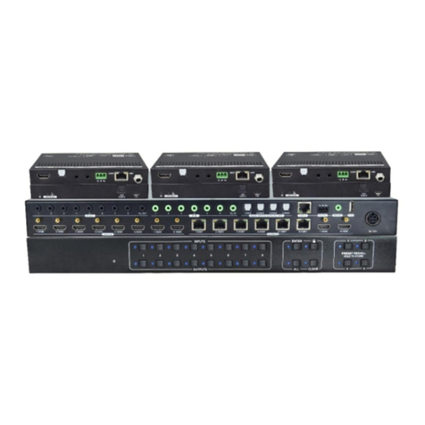
5. Transmitter Panel Description
2
3
4
5 6 7
8
1. Power LED indicator
2. System normal LED
3. HDMI signal input LED indicator
4. Network interface LED indicator
5. Reset button for factory reset
Front Panel
1
9
10 11 12
Rear Panel
6. Switch 1
7. Switch 2
Note: Power the unit while pressing SW1 & SW2
simultaneously for 15 seconds for complete unit
reset.
2 5 6
7
1 3 4
1. Power input
2. HDMI input
3. HDMI output (looped)
4. Audio input
5. Audio output
6. RS232
7. RS232 Switch ON: Pass-Through, OFF: Update
8. USB host
9. Ethernet 10G
10. SFP slot (fibre module not supplied)
11. IR output
12. IR input
User Manual
Scion Tech
SC08.MX2000
Tel: +44 (0) 1635 862484 www.scion-tech.co.uk
Page 5

6. Receiver Panel Description
2 3 4 5 6
1. Power input
2. IR output
3. IR input
4. RS232
5. Audio out 1: From input of transmitter or
HDMI out of receiver
6. Audio out 2: Output from HDMI out port of
transmitter
Front Panel
Rear Panel
1 7 8 9 10 11 12
2
3
4
5 61
1. Power LED indicator
2. System normal LED
3. HDMI signal output LED indicator
4. Network interface LED indicator
5. Reset button for factory reset
6. Reset button for factory reset
Note: Power the unit while pressing SW1 & SW2
simultaneously for 15 seconds for complete unit
reset.
7. HDMI output
8. USB device port 1
9. USB device port 2
10. Ethernet 10G
11. SFP slot (fibre module not supplied)
12. Ethernet 1G
User Manual
Scion Tech
SC08.MX2000
Tel: +44 (0) 1635 862484 www.scion-tech.co.uk
Page 6

User Manual
Scion Tech
SC08.MX2000
Tel: +44 (0) 1635 862484 www.scion-tech.co.uk
Page 7
7. Installing the Encoder (Transmitter)
Note: To ensure adequate ventilation and to prevent overheating, make sure all cables and other
materials are not obstructing the ventilation vents and the transmitter is not placed on another product
that produces or radiates heat.
Connection Functions
HDMI In HDMI input from source
HDMI Out Looped HDMI output for local sink device
Audio In Analogue stereo audio input, software selectable in receiver
settings
Audio In / Out Analogue stereo audio input embedded in HDMI signal or output
from looped HDMI input, software selectable
RS232
Full Duplex RS232 data can be sent to an individual receiver or
broadcast to many receivers. Also used for firmware upgrades,
switch (7) selectable
USB Host USB 2.0 for KVM function.
10G LAN Ethernet connection between a single transmitter and receiver or
connection to 10G Ethernet Network
Fibre Optical connection between a single transmitter and receiver or
connection to a 10G Ethernet Network
IR Out Infra-Red signal output, IR emitter cable
IR In Infra-Red signal input, IR sender cable
Connecting Encoder (Transmitter)
1. Connect the HDMI cable to the HDMI In port and the source device, a premium quality HDMI
cable should be used for 4K resolutions.
2. (Optional) Connect the HDMI cable to the HDMI Out port and the sink device, a premium HDMI
cable should be used for 4K resolutions.
3. (Optional) Connect the stereo audio cable to the Audio In port and the audio equipment using the
3-pin Phoenix terminal provided. Ensure the polarity +/- connections are correct as incorrect
connections may result in damage to the transmitter or the audio equipment.
4. (Optional) Connect the stereo audio cable to the Audio In/Out port and the audio equipment
using the 3-pin Phoenix terminal provided. Ensure the polarity +/- connections are correct as
incorrect connections may result in damage to the transmitter or the audio equipment. The
In/Out function is software selectable, see SC08.CTL200 user manual.
5. (Optional) Connect a USB cable to the USB port and the host device.
6. Connect a CAT6A or better quality patch cable to the 10G LAN port and the 10G Ethernet switch.
7. (Optional) Insert a SFP fibre module in to the Fibre aperture and then insert the fibre connector.
8. (Optional) Connect the IR emitter to the IR Out port and position the emitter in front of the source
device IR window for remote end control.
9. (Optional) Connect the IR receiver cable to the IR In port and position the receptor in sight of the
IR remote.
10. Connect and power the transmitter using the 12V/2.5A power adaptor supplied.

User Manual
Scion Tech
SC08.MX2000
Tel: +44 (0) 1635 862484 www.scion-tech.co.uk
Page 8
8. Installing the Decoder (Receiver)
Note: To ensure adequate ventilation and to prevent overheating, make sure all cables and other
materials are not obstructing the ventilation vents and the receiver is not placed on another product that
produces or radiates heat.
Connection Functions
HDMI Out HDMI output to the sink device
Audio Out 1
Analogue stereo audio output derived from transmitters audio in
port or de-embedded from HDMI signal, software selectable in
receiver settings
Audio Out 2 Analogue stereo audio output de-embedded from the receivers
HDMI output.
RS232 Full Duplex RS232 data can be communicated from an individual
transmitter.
USB Device 1 & 2 USB 2.0 for mouse and keyboard
10G LAN Ethernet connection between a single transmitter and receiver or
connection to 10G Ethernet Network
Fibre Optical connection between a single transmitter and receiver or
connection to a 10G Ethernet Network
IR Out Infra-Red signal output, IR emitter cable
IR In Infra-Red signal input, IR sender cable
Connecting Decoder (Receiver)
1. Connect the HDMI cable to the HDMI Out port and the source device, a premium quality HDMI
cable should be used for 4K resolutions.
2. (Optional) Connect the stereo audio cable to the Audio Out 1 port and the audio equipment using
the 3-pin Phoenix terminal provided. Ensure the polarity +/- connections are correct as incorrect
connections may result in damage to the transmitter or the audio equipment.
3. (Optional) Connect the stereo audio cable to the Audio Out 2 port and the audio equipment using
the 3-pin Phoenix terminal provided. Ensure the polarity +/- connections are correct as incorrect
connections may result in damage to the transmitter or the audio equipment. The In/Out function
is software selectable, see SC08.CTL200 user manual.
4. (Optional) Connect a mouse and keyboard to USB Device 1 and USB Device 2 port.
5. Connect a CAT6A or better quality patch cable to the 10G LAN port and the 10G Ethernet switch.
6. (Optional) Insert a SFP fibre module in to the Fibre aperture and then insert the fibre connector.
7. (Optional) Connect the IR emitter to the IR Out port and position the emitter in front of the source
device IR window for remote end control.
8. (Optional) Connect the IR receiver cable to the IR In port and position the receptor in sight of the
IR remote.
9. Connect and power the transmitter using the 12V/2.5A power adaptor supplied.

User Manual
Scion Tech
SC08.MX2000
9. IR Cable Wiring
Tel: +44 (0) 1635 862484 www.scion-tech.co.uk
Page 9
IR OUT
S
IR IN
S12V
Signal Wire (Black / White)
Ground Wire (Black)
Signal Wire (White)
Ground Wire (Black)
12V Wire (Red)

User Manual
Scion Tech
SC08.MX2000
10. Recommended Network Switches
Tel: +44 (0) 1635 862484 www.scion-tech.co.uk
Page 10
Product Description
Netgear XS708E 8- Port 10G Switch Smart Managed
Netgear XS708T 8- Port 10G Switch Smart Managed + 2 Combo
Netgear XS712T 12- Port 10G Switch Smart Managed + 2 Combo
Netgear XS716T 12- Port 10G Switch Smart Managed + 2 Combo
Netgear M4300-24X 24-Port 10G Switch Smart Managed + 4 Combo
Netgear M4300-48X 48-Port 10G Switch Smart Managed + 4 Combo
Netgear M4300-96X 96-Port 10G Switch Smart Managed + 4 Combo
11. Network IGMP Snooping and Querier Explained
Internet Protocol (IP) multicast is a bandwidth-conserving mechanism for reducing data network traffic
by simultaneously delivering a single stream of information to thousands of recipients. Multicasting is
fundamental to the implementation of IPTV.
This is how it works.
In Diagram 1, none of the network switches have IGMP snooping or querying turned on and so the
network is not multicast enabled. The backbone switch has all the streaming traffic coming into it from
the IPTV Encoders. If we assume each stream is 4 Mbps the backbone switch will carry 4 Mbps x 3
streams = 12 Mbps of streaming traffic.
As the switches do not have IGMP turned on, the streaming traffic will flood the entire network
regardless of whether the user requests a particular stream or not.
Encoders
Core Switch
Switch 3
Switch 2
Switch 1
Decoders
Diagram 1

User Manual
Scion Tech
SC08.MX2000
Tel: +44 (0) 1635 862484 www.scion-tech.co.uk
Page 11
In Diagram 2, all switches have IGMP snooping turned on and the backbone switch has IGMP query
turned on and the network is multicast enabled. Again, the backbone switch has a total of 12 Mbps of
streaming traffic coming into it from the IPTV Encoders.
Switch 1 will only have 8 Mbps of traffic reaching it as a result of the two users who have requested the
same red stream (4 Mbps) and a third user who has selected the green stream (4 Mbps). This is the
distinct advantage of multicasting - the bandwidth used is per stream and not per user.
Switch 2 will only have 4 Mbps of traffic reaching it since only the blue stream has been requested by a
user. There will be no streaming traffic on the port where there is no request for a stream. Switch 3 will
have no streaming traffic since none of the users connected to the switch have requested any streams.
Encoders
Core Switch
Switch 3
Switch 2
Switch 1
Decoders
Diagram 2

12. Application Drawing
SC08.MX100 Controller
Controlling PC
Wi-Fi Router
Wi-Fi Device
User Manual
Scion Tech
SC08.MX2000
Tel: +44 (0) 1635 862484 www.scion-tech.co.uk
Page 12

13. Maintenance
Clean this unit with a soft, dry cloth. Never use alcohol, pint thinner of benzene to clean these devices.
Servicing
Damage requiring service: This product should be serviced by a qualified service engineer if:
●The DC power cord or AC adaptor has been damaged.
●Objects or liquids have entered the housings.
●The product has been exposed to rain.
●The product has stopped working or shows signs of significant change in operating performance or
function.
●The unit has been dropped or severely damaged externally.
Servicing personnel: Do not attempt to service the product beyond that described in these instructions.
Refer all other servicing to authorised serving personnel.
Replacement parts: When parts need replacing ensure the service engineer uses parts specified by the
manufacture or parts that have the same characteristics as the original parts. Unauthorised substitutes
may result in fire, electric shock or other hazards.
Safety check: After a repair or service, ask the engineer to perform safety checks to confirm the product is
in proper working condition.
Warranty
If your product does not work properly because of a defect in materials or workmanship, our Company
(referred to as "the warrantor" ) will , for the length of the period indicated as below, (Parts and labour 2
years) which starts with the date of original purchase ("Limited Warranty period"), at its option either (a)
repair your product with new or refurbished parts, or (b) replace it with a new of a refurbished product.
The decision to repair or replace will be made by the warrantor.
During the "Labour" Limited Warranty period there will be no charge for labour. During the "Parts"
warranty period, there will be no charge for parts. You must mail-in your product during the warranty
period. This Limited Warranty is extended only to the original purchaser and only covers product
purchased as new. A purchase receipt or other proof of original purchase date is required for Limited
Warranty service.
Returning a Product
When shipping the unit carefully pack and send it prepaid, adequately insured and preferably in the
original carton. Include a letter detailing the complaint and provide a day time phone number and/or email
address where you can be reached.
User Manual
Scion Tech
SC08.MX2000
Tel: +44 (0) 1635 862484 www.scion-tech.co.uk
Page 13

Limited warranty limits and exclusions
This Limited Warranty ONLY COVERS failures due to defects in materials or workmanship, and DOES NOT
COVER normal wear and tear or cosmetic damage. The Limited Warranty ALSO DOES NOT COVER
damages which occurred in shipment, or failures which are caused by products not supplied by warrantor,
or failures which result from accidents, misuse, abuse, neglect, mishandling, misapplication, alteration,
faulty installation, set-up adjustments, maladjustment of consumer controls, improper maintenance,
power line surge, lightning damage, modification, or service by anyone other than a Factory Service centre
or other authorized service engineer, or damage that is attributable to acts of God.
THERE ARE NO EXPRESS WARRANTIES EXCEPT AS LISTED UNDER "LIMITED WARRANTY
COVERAGE".THE WARRANTOR IS NOT LIABLE FOR INCIDENTAL OR CONSEQUENTIAL DAMAGES
RESULTING FROM THE USE OF THIS PRODUCT, OR ARISING OUT OF ANY BREACH OF THIS WARRANTY.
(As examples, this excludes damages for lost time, cost of having someone remove or re-install an installed
unit if applicable, travel to and from the service, loss of or damage to media or images, data or other
recorded content. The items listed are not exclusive, but are for illustration only).
PARTS AND SERVICE, WHICH ARE NOT COVERED BY THIS LIMITED WARRANTY, ARE YOUR
RESPONSIBILITY. This returns policy does not affect your legal rights. Details of your legal rights are
available from Trading Standards or Citizens Advice Consumer Service.
Scion Tech Limited
Thatcham, Berkshire, United Kingdom
User Manual
Scion Tech
SC08.MX2000
Tel: +44 (0) 1635 862484 www.scion-tech.co.uk
Page 14
Table of contents
Other Scion-Tech Matrix Switcher manuals

Scion-Tech
Scion-Tech SC04.MX88 User manual

Scion-Tech
Scion-Tech SC36.MX44 User manual

Scion-Tech
Scion-Tech SC04.MX22 User manual

Scion-Tech
Scion-Tech SC04.1404 User manual

Scion-Tech
Scion-Tech SC04.1808 User manual

Scion-Tech
Scion-Tech SC36 MX88 User manual

Scion-Tech
Scion-Tech SC38.MX88 User manual

Scion-Tech
Scion-Tech SC38.MX16 User manual

Scion-Tech
Scion-Tech SC35.MX44 User manual