6
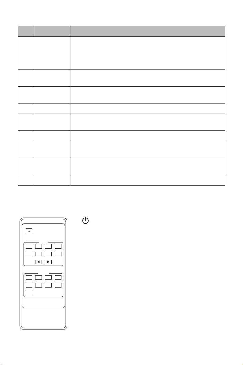
No. Name Function Description
4MENU/ENTER
/UP/DOWN
1. EDID Check: On the initial OLED display screen, press the
"MENU" button to enter the Matrix switching state interface,
then press the "UP/DOWN" button to check the current EDID
information of each HDMI input port.
2. EDID setting: On the initial OLED display screen, press the
"MENU" button to enter the EDID setting interface, press the
"UP/DOWN" button to select the required EDID, and press
the "ENTER" button. A prompt "copy to input:" will appear. Then
press the "UP/DOWN" button to select the input port you need
to set and press the "ENTER" button again to conrm.
3. Baud rate setting: On the initial OLED display screen, press
the "MENU" button to enter the Baud rate interface, press the
"UP/DOWN" button to select the required Baud rate, and
nally press the "ENTER" button to conrm the setting.
4. IP Address Check: On the initial OLED display screen, press
the "MENU" button to enter the IP interface, then press the "UP/
DOWN" button to check the current IP address. Pressing the
"MENU" button again will return to the initial OLED display status.
5POWER
button
Long press the POWER button for 3 seconds to enter the standby
mode, then short press it to wake up the device.
6IR Window IR receiver window only receives the IR remote signal from this
product.
7LOCK button Short press the LOCK button to lock the front panel buttons
(Except the power button); Press it again to unlock.
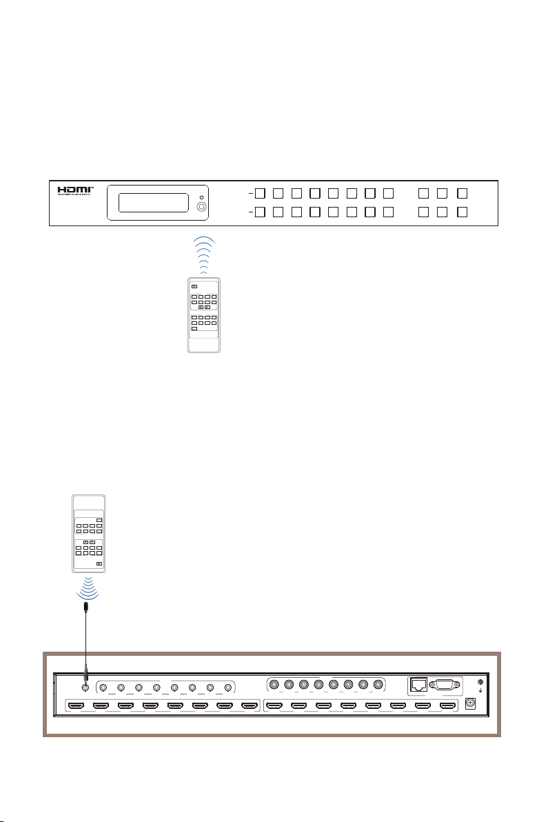
Rear Panel
123
78 9
456
CONTROL
TCP/IP
DC 12V
RS-232
IR EXT
OUT 1 OUT 2 OUT 3 OUT 4 OUT 5 OUT 6 OUT 7 OUT 8IN 1 IN 2 IN 3 IN 4 IN 5 IN 6 IN 7 IN 8
L/R
OUT 1 OUT 2 OUT 3 OUT 4 OUT 5 OUT 6 OUT 7 OUT 8
COAX
OUT 1 OUT 2 OUT 3 OUT 4 OUT 5 OUT 6 OUT 7 OUT 8