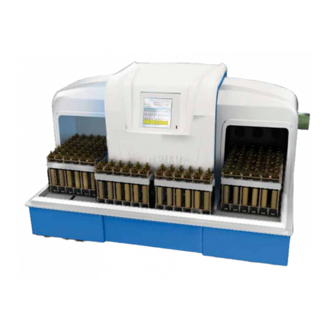
SCP SCIENCE EasyPREP BOD 300 User manual

User Manual
www.scpscience.com
EasyPREP BOD 300

1 Introduction..............................4
2 Cautions, Notes and Symbols . . . . . . . . . . . . . . . .5
3 Warranty & Safety Information...............6
3.1 Measures forYour Protection................6
3.2 Measures forYour Operational Safety .........7
4 Specifications ............................8
5 Installation...............................9
5.1 Before installation........................9
5.1.1 Overview ........................9
5.1.2 Unpacking........................10
5.1.3 Inspection .......................10
5.2 Hardware Installation guidelines .............10
5.2.1 InstallingThe BOD Racks .............10
5.2.2 Cable Connections..................10
5.3 before Software Installation.................11
5.3.1 Computer System Requirements .......11
6 Software Operation ........................12
6.1. Overview of Software.....................12
6.1.1 SoftwareTabs .....................12
6.1.2 Operational Buttons .................13
6.1.3 Hardware Detection .................13
6.2 ProcessTab............................14
6.2.1 Information Field ...................14
6.2.2 Process Sample Field................15
6.2.2.1 Edit sequence tool ................16
6.2.2.2 Process table fields ...............16
6.3 ResultsTab ............................17
6.3.1 Definitions........................17
6.4 UtilitiesTab ............................18
6.4.1 Configuration Process ...............19
6.4.2 Position (Robot) ....................19
6.4.3 Calibrate Pumps ...................20
6.4.3.1 Inhibitor and Seed pumps ..........20
6.4.3.2 Dilution water pump ..............20
6.4.3.3 Waste pump ....................21
6.4.4 Priming/Cleaning...................21
6.4.5 ProODO Probe.....................21
6.4.5 Calibration of the BOD probe ..........22
6.5 Admin-ToolsTab.........................23
6.5.1 Robot ...........................23
6.5.2 Rack Parameters...................24
6.5.3 Calibration of theAutofill Sensor(s) ......26
6.5.4 Instrument Memory Parameters ........27
6.5.5 QC Controls.......................27
6.5.6 Parameters .......................28
7 Guidelines on BOD/CBOD Analysis ............29
7.1 Priming ...............................29
7.2 Peristaltic pump calibration.................29
7.3 Probe Calibration ........................29
7.4 Typical BOD testing Procedure ..............29
7.4.1 Sample Pretreatment: ...............29
7.4.2 DilutionWater Preparation: ...........30
7.4.3 Seed Preparation: ..................30
7.5 QC sample (GGA standard): ................30
7.6 SeedVOL (ml): .........................30
7.7 SampleAnalysis.........................31
7.7.1 Day 0 ...........................31
7.7.2 Day 5 or 7........................31
7.7.3 Process troubleshooting..............32
7.8 Turning off the instrument..................32
8 Probe Operation and Maintenance ............33
8.1 Initial setup ............................33
8.2 Maintenace and storage ...................34
8.2.1 Sensor Maintenance - Dissolved Oxygen .....34
8.2.1.1 Cleaning the OBOD Sensor cap.......34
8.2.1.2 OBOD Sensor Cap Replacement ......34
8.2.1.3 Configuring for the new sensor cap ...35
8.2.1.4 Rehydrating the sensor cap .........36
8.2.1.5 Sensor maintenance - temperature ...36
8.2.2 Sensor Storage .......................36
8.2.2.1 Sensor short-term storage ..........36
8.2.2.2 Sensor long-term storage...........36
9 BOD-300 Peristaltic Pump ..................37
9.1 Peristaltic Pump replacement ...............37
9.2 New Dilution Pump Calibration ..............37
9.3 New Seed Pump Calibration ................38
10 Troubleshooting.............................39
Table of Contents

MANUFACTURED IN CANADA
EU Users:
Contact your local
distributor for disposal
instructions.
Copyright by SCP SCIENCE
All Rights Reserved.
This manual contains proprietary information, which shall not be reproduced or transferred to other
documents or disclosed to others without prior written permission from SCP SCIENCE.
Disclaimer: Products are supplied for laboratory use only. SCP SCIENCE assumes that only trained and qualified individuals, familiar with procedures
suitable for the safe operation of these instruments, will handle them.Our customers are solely responsible for the safe operation, handling and use of these
products.
CERTIFIED to comply with the following EMC,Safety and RoHS standards:
NF EN 61000-4-2(2009), NF EN 61000-4-3(2006,+A1:2007+A2:2010), NF EN 61000-4-4(2004,+A1:2010), NF EN 61000-4-5(2005), NF EN 61000-4-
6(2009),NF EN 61000-4-11 (2004),FCC Part 15:2012,Subpart B, ClassA, CAN/CSA-C22.2 NO.61010-1-12 Part 1: 3rd ed.,CAN/CSA-C22.2 NO. 61010-2-
010:15,CAN/CSA C22.2 NO. 61010-2-081:15,UL 61010:Part 1 3rd ed., UL 61010-2-010:2014 3rd ed.,UL61010-2-081: 2015 2nd ed.,IEC 61010-1:2010
3rd ed.,IEC 61010-2-010: 2014 3rd ed.,IEC 61010-2-081:2015 2nd ed., EN50581:2012.
Shipment:Courier or truck FOB.Warehouse locations:Baie d'Urfé (Montreal), QC,Canada; Champlain, NY,USA; Courtaboeuf, Paris,France. Insurance covering
the full value of the shipment is included with the transportation charges. If you wish to select a specific carrier and/or have insurance to cover your shipment,
please contact us immediately.
Claims: SCP SCIENCE takes great care in the packaging of goods prior to shipment. In the event that breakage occurs during shipment, claims for
damaged merchandise must be made to the transport company and reported to SCP SCIENCE within five days of receipt of order.The damaged goods and
original packaging must be kept, and a damage report claim must be filed with the transport company. Claims for short shipments (merchandise manifested but
not received) should be made immediately with SCP SCIENCE.
Returns: No returns can be accepted without prior approval. Please contact SCP SCIENCE for a return authorization number and shipping instructions
before returning merchandise.Restocking charges may be applicable.
Service Department • Technical Support
CORPORATE
HEADQUARTERS USA FRANCE GERMANY
21800 Clark Graham
Baie D’Urfé (Montréal),
Quebec,H9X 4B6 Canada
3rd Party Distribution Center
348 Route 11,Champlain,
N.Y.12919-4816
12Ave. de Québec, Bat.Iberis
SILIC 642,91965 Courtaboeuf Alte Marktoberdorfer Straße 14,
87616 Marktoberdorf
Phone:+1 (514) 457-0701
+1 (800) 361-6820
Fax: +1 (514) 457-4499
+1 (800) 253-5549
Phone:+1 (800) 361-6820
Fax: +1 (800) 253-5549 Phone:+33 (0) 1 69 18 71 17
Fax: +33 (0) 1 60 92 05 67 Phone:+49 (0) 8342-89560-61
Fax: +49 (0) 8342-89560-69

Version 1.0
4 |
1 Introduction
EasyPREP BOD-300 is an automated offline system for the sample preparation and analysis for Biochemical Oxygen Demand (BOD).
With three liquid-handling peristaltic pumps,the EasyPREP BOD-300 adds seed and nitrification inhibitor as well as dilution water to
perform sample dilutions.The low maintenance dissolved oxygen (DO) probe with either optical or membrane technology incorporates a blade
stirrer,keeping the sample homogeneous and accelerating probe equilibration for DO measurement.The software manages sample's initial to
final DO measurement and BOD calculations.User-definable QC control allows flagging and validation of analytical batches.Preparation and
results conform to established methods ISO 5815-1/EN-1899-1/2./5814 (2012),EPA 405.1 and Standard Methods 5210B.
The EasyPREP BOD-300 accommodates 60 ml, 165 ml or 300 ml bottles for optimized throughput,allowing the analysis of up to 60
position (300 ml bottles),72 position (60 ml bottles) or 72 position (165 ml bottles) without operator intervention.
Biochemical Oxygen Demand (BOD) analysis is an empirical bioassay-type procedure which determines the dissolved oxygen consumed
by microbial life while assimilating and oxidizing the organic matter present in the sample water.The standard test conditions include dark
incubation at 20 °C for a specific time period (often 5 days, or 7 days),in an entirely filled and closed bottle. Dissolved oxygen (DO) is
measured before and after incubation,and the BOD is computed from the difference.
Carbonaceous biochemical oxygen demand (cBOD) method differs from the BOD method.cBOD includes nitrification inhibitor added in the
bottles on Day 0.Nitrification inhibitors available in the market include: allylthiourea (ATU) or 2-chloro-6-(trichloromethyl) pyridine (TCMP).The
nitrification inhibitor is added by its own peristaltc pump in liquid form.

Version 1.0
| 5
2 Cautions, Notes and Symbols
SYMBOL DESCRIPTION SYMBOL DESCRIPTION
VVoltage lMains on
~Alternating current 0Mains off
ACurrent Attention,consult accompanying documents
Hz Frequency Protective conductor terminal
FFast-acting fuse WWatts
Cautions, warnings and notes are included throughout this manual.
CAUTION
A caution is used to emphasize information pertaining to procedures that,if not strictly followed, may result in damage or destruction
to the instrument or improper instrument operation.
WARNING
A warning is used to emphasize information about dangerous or hazardous conditions relating to the operation,cleaning or
maintenance of the instrument that may result in personal injury.
NOTE
A note is used to emphasize procedures or conditions that may be misinterpreted or overlooked, and to clarify potentially confusing
situations.
NOTE
WARNING
CAUTION

Version 1.0
6 |
3 Warranty & Safety Information
SCP SCIENCE warrants this product free from defects in workmanship and materials for one (1) year from date of purchase.
Should the unit malfunction,please contact SCP SCIENCE’s Service Department or your local distributor for further instructions.
The warranty is void if the instrument shows evidence of tampering or has been subjected to excessive moisture,heat, corrosion or other
misuse.
SCP SCIENCE shall not be responsible for any damage or losses,however caused, resulting from improper installation or misuse of this
product.
Products are supplied for laboratory use only and should not be used for any household,medical or therapeutic application.
SCP SCIENCE presumes that only trained and qualified individuals,familiar with procedures suitable for the safe operation of these
instruments,will handle them. Our customers are solely responsible for the safe operation,handling and use of these products.
MINIMUM SAFETY CONSIDERATIONS MUST BE FOLLOWED WHEN WORKING WITH EasyPREP BOD-300 IN ORDER
TO MAINTAIN GOOD LABORATORY PRACTICES:
3.1 MEASURES FOR YOUR PROTECTION
When using chemicals and solvents,comply with the instructions of the manufacturer and the general lab safety rules.
Always wear safety glasses when handling samples and reagents.
No User Serviceable parts inside.
WARNING
CAUTION
CAUTION

Version 1.0
| 7
3.2 MEASURES FOR YOUR OPERATIONAL SAFETY
Make sure the EasyPREP BOD-300 is placed on a surface capable of supporting 200 pounds (100 kg).
EasyPREP BOD-300 requires a clearance of five inches (12.7cm) on all sides.
If moving the system,always use 2 people and do not lift by the Kydex®or Corian®panels. Lift by the bottom aluminum frame instead.
Keep hands and fingers free of the system when it is moving to reduce the risk of pinching.
Always plug the EasyPREP BOD-300 in a properly grounded three-prong electrical outlet (100-240V receptacle).
Use a stabilized constant voltage AC power supply, with a voltage within +/-5% of the specified level.
Always use the provided mains power cord or one with the same manufacturer’s specifications.
If the BOD-300 is used in a manner not specified by the manufacturer,the protection provided by the equipment may be impaired.
WARNING
CAUTION
WARNING
WARNING
WARNING
CAUTION
WARNING
WARNING

Version 1.0
8 |
4 Specications
Dimensions Electrical
Width 120 cm (47 in) Model Number EasyPREP BOD-300
Depth (Total) 81.3 cm (32 in) Voltage 115~230V
Depth (Base) 63.5 cm (25 in) Power 130W
Height 64 cm (25 ¼ in) Frequency 50/60Hz
Environmental
Relative Humidity 30% to 80%
Altitude up to 2000 m
Installation Category ll
Pollution Degree 2
Ambient OperatingTemperature 15 °C to 40 °C
ProODO Probe Specifications
The specifications listed below are system specifications for the ProOBOD probe when used with a BOD-300 instrument.
These specifications are subject to change without notice.
Dissolved Oxygen (mg/L) Temperature (°C)
Sensor type Optical (dynamic luminescence quenching lifetime detection) Range 5 to 70 °C
Range 0 to 50 mg/L Accuracy ±0.2 °C
Accuracy 0 to 20 mg/L ±0.1 mg/L or 1% of reading,whichever is greater 20 to 50 mg/L
±10% of reading Resolution 0.1 °C
Resolution 0.01 or 0.1 mg/L (auto-scaling)
Barometer (mmHg)
Range 375 to 825 mmHg
Accuracy ±1.5 mmHg from 0 to 50 °C
Resolution 0.1 mmHg
Fuses-Ratings
The Power Supply has an over voltage, overload and short circuit protections.
NOTE

Version 1.0
| 9
5 Installation
5.1 BEFORE INSTALLATION
5.1.1 Overview
2
3
41
18 15
17
16
6
Figure 1. FrontView
LABEL DESCRIPTION
1 X-arm
2 Y-arm
3 Z-arm
4 Dual Probe shown
5 Probe Holder
6 Table
7 Rinse Pump
8 10 pin connector
9 Dilution Pump
10 Seed Pump
LABEL DESCRIPTION
11 Inhibitor Pump
12 Dilution Pump (Optional)
13 Inhibitor Pump (Optional)
14 Seed Pump (Optional)
15 Power in receptacle
16 Power Indicator
17 Power ON/OFF Button
18 USB Receptacle
19 Autofill sensor
20 Decapper
10
12 13 14
9
11
Figure 1. RearView
5
7
8
19
20

Version 1.0
10 |
5.1.2 Unpacking
EasyPREP BOD-300 may be attached to the packaging with bolts.Remove them prior to lifting the system out of the box.The system
weighs approximately 100 kg. Use two people to lift by the bottom frame and place the system on a flat surface where it will be used.Save the
packing material for further use.
5.1.3 Inspection
Ensureall ofthe parts areincluded in theshipment.There maybe someaccessories thathave been packagedin thesame boxas EasyPREP
BOD-300.If damage is observed,contact the carrier to make a claim and then contact the Service Department.
5.2 HARDWARE INSTALLATION GUIDELINES
BOD-300 requires installation in such a way that the ON/OFF button has a minimum clearance of 8 in. (20 cm)”
5.2.1 InstallingThe BOD Racks
Place the BOD racks on the top table,using the positioning pins provided on the top table to align them.
Bottle caps must be removed by hand prior to starting sequence, unless the BOD-300 decapping/capping accessory is installed.The
BOD-300 decapping/capping acccesory is not compatible with acrylic caps.BOD 65 ml,300 ml PE bottle caps (010-420-020) must
be used with the decapping/capping accessory for 300 and 60 ml bottles.
5.2.2 Cable Connections
Make sure that the power button is turned off.
• Connect the power cable to the receptacle located on the end of the X-arm.(Figure 2)
• Connect the USB cable to the USB port located on the end of the X-arm.(Figure 2)
Do not connect the USB cable to the computer yet.
Figure 2. Power and USB ports
CAUTION
CAUTION
POWER SWITCH
POWER INDICATOR
POWER CORD FROM OUTLET
USB CABLE FROM
COMPUTER

Version 1.0
| 11
5.3 BEFORE SOFTWARE INSTALLATION
5.3.1 Computer System Requirements
• PC Processor:1GHz or superior.
• RAM memory: 1 GB RAM.
• Disk min.space: 1 GB free.
• Ports:1 USB port available.
• Operating System:Windows 7 and 10.

Version 1.0
12 |
6 Software Operation
6.1. OVERVIEW OF SOFTWARE
6.1.1 SoftwareTabs
The User Interface has four tabs:PROCESS, RESULTS, UTILITIES and ADMIN-TOOLS.
Figure 3. Four tabs to navigate the software
• PROCESS tab:Where the sequence is programmed.
• RESULTS tab:Where results are displayed, in real-time.
• UTILITIES tab:Where the basic method parameters can be adjusted,in addition to:
1. Probe calibration and reading.
2. Liquid dispensing parameters.
3. Priming/Cleaning.
• ADMIN-TOOLS tab:Password protected, used to configure the system in the following ways:
1. Motion speed when manually setting the positioning of robotic arm.
2. Liquid dispensing parameters (speed,delay).
3. QC Controls.
4. Method parameters for QC samples

Version 1.0
| 13
6.1.2 Operational Buttons
There are four (4) buttons on the title bar,as shown below.
Figure 5. Four buttons to control the test progress
• “Run”button is blue when enabled and grey when disabled.
• “Pause”button is blue when enabled and grey when disabled.It will show as “Resume”after being pressed.When resumed, the
sequence will continue from the break point.The pause will only take place once the commands in the que are completed. This may
take up to 1 minute to complete.
• “Stop”button goes red when enabled and grey when disabled.When the sequence is interrupted, the test will stop after the current
action is finished and the result table is displayed.If the “Run”button is pressed again, the sequence will restart from the beginning.
• "Emergency stop".The system stops completely.The software needs to be closed before restarting the tests.
6.1.3 Hardware Detection
Figure 6. Indicators to show the status of communication with hardware.
The six (6) for dual probe configuration and 4 for single probe configuration indicators at the bottom of the screen indicate whether the
modules have been detected by the instrument.A red indicator signifies that a module has not been detected or is faulty.A green indicator
signifies that the module has been detected and is ready for use.
ROBOT indicator is for the robotic system.
ProODO #1 indicator is for the first BOD Probe.
ProODO #2
indicator is for the second BOD Probe.
Pump 1 indicator is green to indicate that the software is communicating with the Pump module for the first BOD Probe.
Pump 2 indicator is green to indicate that the software is communicating with the Pump module for the second BOD Probe.
EasyPREP Memory indicator is green to indicate that the software is communication with the on board computer.
If the indicator remains red after start up, go to theTroubleshooting section (Section 10,page 39).
CAUTION

Version 1.0
14 |
6.2 PROCESS TAB
The PROCESS tab is used to build sequences for automated BOD/cBOD analysis. Sequences can be saved by pressing the save icon
or recalled by pressing the search file icon .
Figure 7.Process tabs for single and dual probe
6.2.1 Information Field
Figure 8. Information field for single and dual probe
• Legend:Every line in the sequence is represented by a color in the rack visualization.
Figure 9. Legend field
• Once the“Run” button is pressed, the indicator representing the bottle in process turns blue;
• Once the analysis is complete,the indicator representing the bottle in question turns green.
• If the measurement of the bottle is not within an acceptable for Day 0 reading, the bottle in in question turns orange.
• The system will prompt the user that failed bottles on Day 0 maybe be re-run.The user may remake the bottle,aerate the bottle or
accept the value measured.The system will wash the probes between bottles.

Version 1.0
| 15
• Rack:There are 3 possible rack positions:A,B and C.
Figure 10. Rack field
• “Operator’s Name”:A field for the operator's name.This information is stored in the results file.This is only stored after the run button has
been pressed.
• “Comment/Remark”:A field for any comments.This information is stored in the results file.This information is only stored after the run
button has been pressed.
Figure 11. Operator's Name and Comment/Rack fields
6.2.2 Process Sample Field
Figure 12. Input sample field

Version 1.0
16 |
6.2.2.1 Edit sequence tool
• Add task to input process table.
• Makes a correction to selected line in input process table.
• Delete last line or selected line in input process table.
• Clears the entire process table.
• Saves the current task list in the process table.
• Loads a previously saved tasklist.
Figure 13. Edit sequence fileds.
6.2.2.2 Process table fields
Figure 14. Input zone to build test sequences.
• "RACK:" Position of the rack on the rack table.Select between rack positions A,B or C.
• "ID":Unique ID of the rack in use.
• "BOTTLE":Position of the bottle in the rack (range depends on the Rack #).
• "ID":Unique ID of the bottle.
• "TYPE":Select among Blank, Seed, QC,Sample.
• "METHOD":Select between BOD and cBOD.
• "METHOD RINSE":Check to rinse between samples. If rinse is checked the probe is washed between each bottle. Unchecked between
bottles and checked between samples to rinse probes between samples.
• "SAMPLE ID":Unique ID of the sample. If the sample ID is the same as another sample the software will calculate the average value
based upon it meeting the QC requirements.
• "VOL (ml)":Volume in ml of the sample pipetted into the bottle.
• "DL":Dilution factor.This is the dilution factor prior to aliquotting the sample.
• "SEEDVOL (ml)":Volume of seed water to be added to the bottle.Sample and seed volumes will be accepted if the constraint "Sample
volume + Seed volume + Inhibitor volume <=Total volume" is satisfied. When the test is running,the first 2/3 of the dilution water is
added,then the seed, and then the inhibitor volume request (if a liquid is used).The final 1/3 of the dilution water is added after the seed/
inhibitor addition.
• "INHIBVOL (ml)":Volume of inhibitor to be added to the bottle.

Version 1.0
| 17
6.3 RESULTS TAB
The RESULTS tab provides the user with a real-time view of their results.The results are saved automatically into a .csv file located in
BOD-300/Results folder.
Figure 15. Screenshot of the ResultsTab.
Results can be sorted by Probe Pair,by Individual Probe or by Bottle when two probes are used.
• Sorting by Probe Pair will present the results following the anaysis order.
• Sorting by Individual probe will list all results from probe 1 followed by probe 2.
• Sorting by Bottle will list the samples in sequential order
6.3.1 Definitions
All the following parameters are stored in the results file.
• “Date”:A field for the date of test.
• “Operator”:A field for the operator's name.
• "Cell label and cell value":Inspired by an Excel table, in order to show the clicked cell on the results table and its value.
• “Rack #”:Position of the rack on the rack table.
• “Rack ID”:Unique ID of the rack in use.
• “Bottle #”:Position of the bottle in the rack.
• “Bottle ID”:Unique ID of the bottle used in the test.
• “Type”:Type of sample selected in the sequence and used in the test.

Version 1.0
18 |
• "Method":BOD or cBOD method selected in the sequence and used in the test.
• “Sample ID”:Unique ID of the sample in use.
• “Sample volume”:Volume input into the sequence and used in the test.
• “Seed volume”:Volume input into the sequence and used in the test.
• "InitialTime":Initial temperature of the sample during Day 0 test.
• "FinalTime":Is the time of day sample has been measured.
• “Initial DO”:Dissolved Oxygen measured in the initial test.
• “Final DO”:Dissolved Oxygen measured in the final test.
• "FinalTemp (C)":Temperature of the sample during the final test.
• “Depletion”:Calculated by subtraction of final DO from initial DO. .
• “BOD/cBOD (mg/L O2)”:Calculated sample DO depletion.
• “Remark”:Comments on data out of range.
• In Remarks,a bottle which failed measuring criteria will be marked with <R>.If remeasured and bottle passed the criteria, <RM>will
appear to the right of <R>.
6.4 UTILITIES TAB
In the UTILITIES Tab,the following functions are accessible:
• Configuration process.
• Position (Robot).
• Pump calibration.
• Seed Pump
• Inhibitor Pump
• DilutionWater Pump.
• Waste Pump.
• Priming/Cleaning.
• ProODO Probe.
Figure 16. Screenshot of the Utilities tab.

Version 1.0
| 19
6.4.1 Configuration Process
Select sequence test from Day 0,Day 5, Day 7 or Day 20 (figure 18).
• "Day 0":Measurement of the initial dissolved oxygen concentration following the test sequence on day 0.
• "Day 5":Measurement of the final dissolved oxygen concentration on Day 5.
• "Day 7":Measurement of the final dissolved oxygen concentration on Day 7.
• "Day N":Measurement of the final dissolved oxygen concentration on Day N. N is user definable.
• "Select Bottle”:Choose capacity of bottles to be used.
• “TotalVolume”:Actual volume of the BOD bottle.
Figure 17. Configuration Process field.
6.4.2 Position (Robot)
• "POSITION (ROBOT)":Manually moves the robot arm to the designated rack and bottle #.When decap is installed
the robot will remove caps.
• "Rack":Choose the rack position.
• "Bottle":Choose the bottle position.
• "Use Probe":Move the arm to lower the probe into the designated bottle.
• "Use Pump":Move the arm to align the liquid transfer tubes with the opening of the bottle.
• "PrimeAll": Used to prime all BOD lines. Robot will move to the wash station.
Figure 18. Position (Robot) field.

Version 1.0
20 |
6.4.3 Calibrate Pumps
Figure 19. Calibrate pumps.
6.4.3.1 Inhibitor and Seed pumps
Calibration function of the pump for seed/ATU addition (Figure 19).
• Move the robot arm to one of the bottle locations (e.g.A1) in“Position (robot) – Use Pump”.
• Under "Volume" and "Set":Type in the volume of water to be dispensed by the pump (generally 10-20 ml).
• Press "RUN PUMP" and collect the dispensed water in a pre-weighed bottle.
• Measure the dispensed water,convert to volume and type the value in "Measure".
• Press "CALIBRATE",the new pump flow rate will be reset under "Increment".
Only press Calibrate ONCE.
6.4.3.2 Dilution water pump
Calibration function of the pump for dilution water addition (Figure 19).
• Move the robot arm to one of the bottle locations (e.g.A1) in“Position (robot) – Use Pump”.
• "Duration":Type in the number of seconds for the pump to run (< 19 seconds).
NOTE
Table of contents
Other SCP SCIENCE Laboratory Equipment manuals
Popular Laboratory Equipment manuals by other brands

Helmer Scientific
Helmer Scientific i.Series PF15-Pro Instructions for Use and Operation Manual

ThermoFisher Scientific
ThermoFisher Scientific SpeedVac DNA130 Installation and operations

BiOptic
BiOptic Qsep1-Lite Operation manual

BioLAB
BioLAB BLVR-202 Operation manual

Microm
Microm HM 355 S instruction manual

Atlas Scientific
Atlas Scientific IoT pH meter user guide

Nordson
Nordson ProcessMate 5000 operating manual

Ocean Optics
Ocean Optics USB-ISS-UV/VIS quick start guide

Thermo
Thermo 4862 Operating and maintenance manual

USA Lab
USA Lab RE-501 manual

Cognionics
Cognionics Quick-20 user guide

Elisabeth Pharmacon
Elisabeth Pharmacon Zephyrus Gel Box Enclosure 2.0 Series Instructions for use