P:\INST-INSTRUCTIONS\Electrical Devices\INST-S4200 REV - 11/20 Page 3
SECURITY DOOR CONTROLS ■ WWW.SDCSECURITY.COM
[t] 800.413.8783 ■ 805.494.0622 ■ E-mail: service@sdcsecurity.com ■ 801 Avenida Acaso, Camarillo, CA 93012 ■ PO Box 3670, Camarillo, CA 93011
STEP 1: PREPARE DOOR
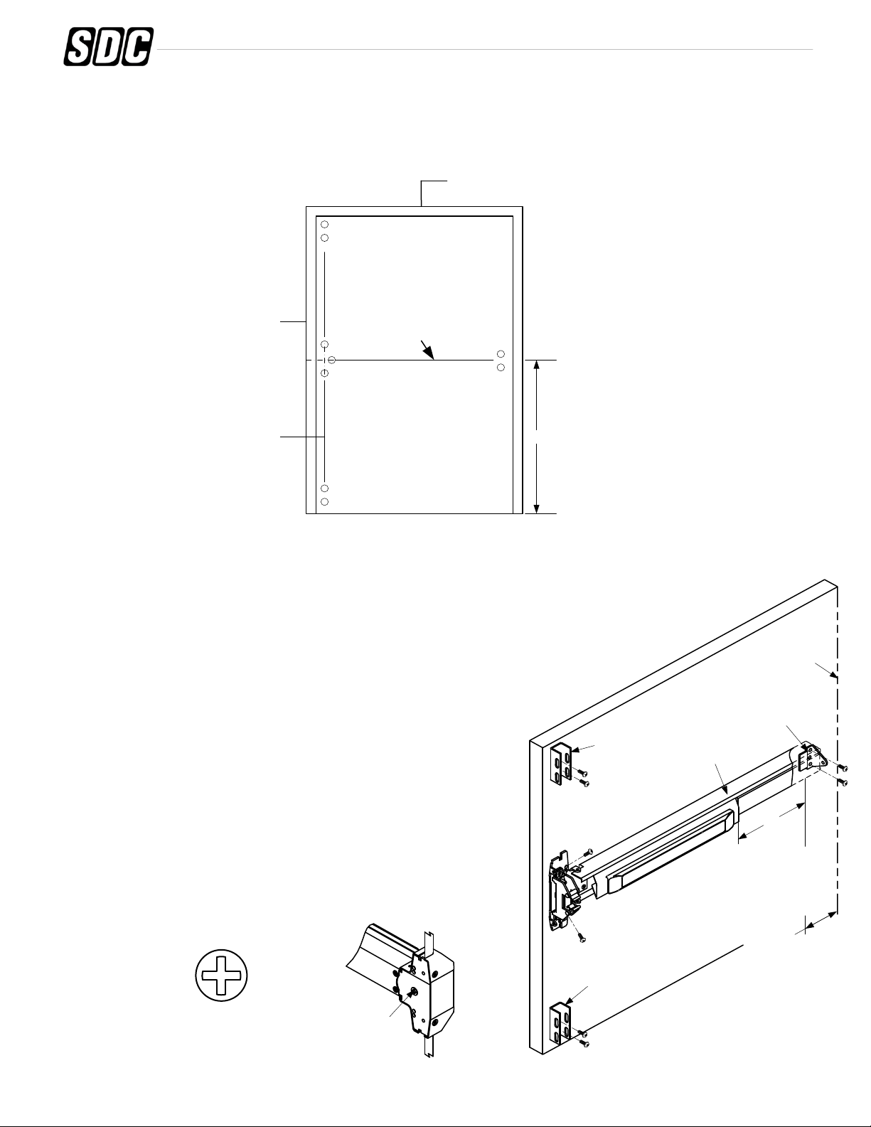
1. Mark position of holes on the door with templates. (See Figure 1.)
2. Spot and drill all holes as marked on door for device chassis, top & bottom latch mounting brackets and end cap
bracket.
40"
STEP 2: INSTALL BRACKETS, DEVICE & TRIM
1. Remove chassis cover from chassis assembly and end cap from end cap bracket.
2. The length of devices are precut for 36" wide door use, no additional cutting is necessary.
Note:
This device can’t be cut shorter than the standard width or will damage the ELR.
3. Mount device horizontally to the drilled position securing it with the supplied
mounting screws, or with device trim.
(See Trim Installation Instructions.)
4. Make sure that the trim actuating shaft can insert into device cam.
(See the figure of Device Cam below.)
5. Install end cap bracket on device then screw to door.
(Make sure the device is level.)
6. Install two mounting brackets on top and bottom of the door.
(See Figure 2.)
INSIDE FACE OF DOOR
Figure 1
℄
Of Top & Bottom latches
Tape the templates on inside
face of door, mark the
mounting holes onto door.
(Mark mounting holes for trim
on outside face of door at the
same time of device install.)
JAMB
40" To finished floor
Standard centerline height of
device is 40" above the
finished floor.
Mark ℄ of device
TOP FRAME
Device Cam
Insert Trim actuating shaft
Into Device Cam
Device Cam
Mounting
Bracket
End Cap
Bracket
Device
2"
Minimum
A
Mark mounting
holes thru End
Cap Bracket after
Device is level
Mounting
Bracket
Figure 2
Hinge Stile
Edge of door