SDC 917 EntryCheck User manual

Installation
12-24V AC/DC: Connect 12 or 24V (AC or DC, 50 or 60Hz) to these two terminals to provi e the power
necessary to operate the keypa . For most installations, the keypa an electric lock will share the
same power supply.
Output 1: Electric locking evice control relay (3 terminals). Connect the positive (+) lea from the
power supply that is being use to power the locking evice to the (COM) terminal. If the locking evice
is a Fail Safe (power to lock) type, connect the positive lea of the locking evice to the Normally
Close (N.C.) terminal. If the locking evice is a Fail Secure (power to unlock) type, connect the
positive lea of the locking evice to the Normally Open (N.O.) terminal. Connect the negative wire of
the locking evice to the negative (-) lea of the power supply that is being use to power the locking
evice
EG.: This terminal is for connection to an Request-To-Exit Egress evice. Connect one lea from the
egress button to the EG terminal, an the other lea to the negative power supply output that is
powering the keypa . The egress evice must provi e a N/O momentary contact. Multiple evices can
be wire in parallel.
Tampe N.C.: These terminals are not use .
Inductive Kickback P otection: In uctive Kickback is a strong electric pulse (up to 500v) generate
by electric locks when power is remove . It is strong enough to estroy the relay contacts in the 917
keypa , unless a protective evice is a e to the circuit. Inclu e with the 917 keypa is a io e that
can provi e this protection for DC-powere electric locks (except magnetic locks). For magnetic locks
an all AC-powere locks, use an MOV instea . Wire it into the circuit as seen in the iagram to the
left, taking note of the polarity for the io e (i entifie by the silver ban ) an locating it as close as
possible to the electric lock.
Featu es
Install a io e or MOV to
protect against in uctive
kickback.
SECURITY DOOR CONTROLS
3580 Willow Lane, Westlake Village, CA 91361-4921 • (805) 494-0622 • ax: (805) 494-8861
www.sdcsecurity.com • E-mail: [email protected]m
P:\INSTALLATION INST\ACCESS CONTRLS\INST-917 Stan Alone.vs Rev G 03-10 Page 1
INSTALLATION INSTRUCTIONS
917 Ent yCheck Stand-Alone Keypad
TM
Power
Supply
Electric Locking
Device
(-) (+) 917
Keypa
The SDC 917 Entrycheck Stan alone Keypa is esigne to control electric locking evices such as
electric oor strike, magnetic locks or electrifie locksets.
Up to 99 ifferent user co es may be programme into the 917, making it possible to allow or eny
entry to any one user, without affecting the co es use by the other 98.
Choice of latching o timed output;
Timed output: When an authorize PIN co e is entere , the relay is activate , unlocking the oor per
programme time from 1 to 999 secon s. A momentary ry contact connecte to the (EG) Request-to-
Exit input activates the time output. PIN co es will not activate the latching function when the keypa
is programme for time operation.
Latching Output: Entering an authorize PIN co es latches the relay output ON or OFF.
A momentary ry contact connecte to the (EG) Request-to-Exit input will also activate the latching
output. The lock is maintaine in the ON or OFF mo e until a PIN co e is re-entere or (EG)
Request-to-Exit input is actuate . PIN co es will not activate time output when the keypa is
programme for latching operation.
Request-To-Exit Input: A Request-to-Exit evice with a momentary, N/O ry contact can be use for
time egress operation without entering an access co e. The evice may be an Exit Switch, Sense Bar
or Request-to-Exit PIR sensor an is typically locate within the secure area. When latching operation
is chosen, a maintaine or momentary, N/O ry contact switching evice locate remotely or a jacent to
the oor may be use for ON/OFF latching without entering an access co e.

Installation Examples
The examples below represent common installation metho s.
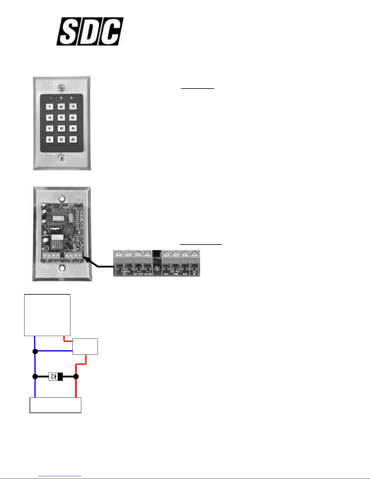
This example uses a single 12VDC power supply to power both
the 917 keypa an a 12VDC Fail Secu e electric oor strike.
The N.O. output terminal is use to connect a fail secure evice
such as a fail secure electric strike.
Example #1
This example uses separate power supplies for the 917 keypa an two electric locks. This is the preferre metho
when there are multiple locks being controlle , to help protect the keypa from increase in uctive kickback surges
cause by the multiple locks.
Example #3
This example uses a single 24VDC power supply to power both
the 917 keypa an a 24VDC Fail Safe magnetic lock. The
N.C. output terminal is use to connect this evice. Connection
of a N.O. egress evice is also inclu e in the circuit.
Example #2
P:\INSTALLATION INST\ACCESS CONTRLS\INST-917 Stan Alone.vs Rev G 03-10 Page 2
Powe Supply
24VDC Output
120VAC
input
Magnetic Lock
24VDC
(+) (-) MOV
N/O
Eg ess
Device
Powe Supply
12VDC Output
120VAC
input
(+) (-)
Powe Supply
24VDC Output
(+)
120VAC
input
(-)
MOV
N/O
Eg ess
Device
Magnetic Lock
24VDC
MOV
Magnetic Lock
24VDC
Code Compliant Fixed Time
Eg ess of Ent ance Eg ess
Doo s. Fo Keypads
P og ammed fo Timed Ent y o
On/Off Latching:
The two following evices are require
to comply with National, State an
Local Co e Criteria per Co e Section
Title “Access Controlle Egress
Doors” Both device contacts are wired
in series with the failsafe lock power
input. Loss of power to either egress
device unlocks door.
SDC 423MU or 413MNU Failsafe exit
switch with fixed 30 sec. time
SDC 42MD-31DW Failsafe PIR sensor.
ASSOCIATED PRODUCTS – TIMED EGRESS CONTROLS
Adj. timed Eg ess fo ON/OFF
latching Keypads:
Wire contacts in series with lock power.
SDC MSB55V-10TD or PSB560V-
10TD Egress Bars with timer mo ule
SDC 423U or 413NU Exit Switch with
a justable timer.
SDC 2MD-31D-W Time PIR Exit
Sensor with a justable timer.
SDC 10TD Mini Timer Mo ule for REX
evices without timers.
Adj. Timed Eg ess fo Timed
Ent y Keypads:
Keypads programmed for timed entry,
connect to (EG) REX input.
SDC MD-31D-W PIR Exit Sensor
SDC MSB55V or PSB560V Egress Bar
SDC 423U or 413NU Exit Switches.
120VAC
input
Elect ic St ike
12VDC
Dio e
(+) (-)
Powe Supply
12VDC Output
Fo Keypads P og ammed fo ON/OFF Latching:
Connect momentary contacts to (EG) REX input
Pulse on, Pulse off.
SDC 423MU or 413NU Exit Switches.
Fo Keypads P og ammed fo ON/OFF Latching
o Timed Ent y:
Wire contacts in series with lock power.
SDC 491 or 492 Blue Emergency Release Stations.
SDC 14-2 or 492 7 Day Timer, Sche ule Daily Locking/
Unlocking
Access Cont ol Powe Supplies
1 Amp Class 2 Power Supply/Chargers
621PJ Power Supply, with Enclosure an Plug-In
Transformer.
621J Power Supply, with Enclosure, less Transformer.
602RF UL 294, Power Supply, 12"x12"x4" Cabinet, built-in
Transformer.
ASSOCIATED PRODUCTS – REMOTE ON/OFF CONTROL

P og amming
All program settings are protecte by a Master Co e, to prevent unauthorize changes.
When setting up the 917 keypa for the first time (or if the Master Co e has been lost) the first step is to program the
Master Co e you’ like to use.
Maste Code, Initial Setup:
1) Disconnect power from the keypa .
2) Set the DAP jumper to “ON”
3) Connect power to the keypa . The keypa shoul start beeping continuously, an the yellow LED
flashing continuously.
4) Move the DAP jumper to “OFF”. The keypa shoul stop beeping, an the yellow LED lit stea y.
5) Enter:
0 MMMM #
into the keypa , where “MMMM” is the four- igit Master Co e you’ like to
use.
Example: 0 1234 # woul set the Master Co e to “1234”
Othe P og amming:
Note: All of the programming examples use a Master Co e of “1234” but that’s not a visable in actual practice,
because it’s too easy for unauthorize personnel to guess.
P:\INSTALLATION INST\ACCESS CONTRLS\INST-917 Stan Alone.vs Rev G 03-10 Page 3
P og amming Patte n: As you can see, all programming entries follow the same pattern:
[Maste Code ] + [numbe ] + [info mation to ente , if any] + [# ]
[Maste Code ] sets the keypa into programming mo e. Programming mo e is i entifie by the
keypa ’s yellow LED being lit stea y.
[Numbe ] tells the keypa which feature to change. 0=Master Co e; 1=User Co e; etc.
[# ] completes the programming sequence.
Description Keypa Entry Example
(1) Set User Co e
MMMM 1 DD UUUU #
MMMM = Master Co e
DD = User ID Number, 01-99
UUUU = User Co e, 4-8 igits
1234 1 47 7890 #
Using a Master Co e of “1234”
set User ID “47”
to a User Co e of “7890”
(1) Delete User Co e
MMMM 1 DD #
MMMM = Master Co e
DD = User ID Number, 01-99
1234 1 21 #
Using a Master Co e of “1234”
elete the User Co e
for User ID “21”
(40) Set Relay Time
MMMM 40 TT #
MMMM = Master Co e
TT = Relay Time, 01-999 secon s
1234 40 05 #
Using a Master Co e of “1234”
set the Relay Time to 5 secon s
(0) Change Master Co e
MMMM 0 MMMM #
MMMM = Master Co e
MMMM = New Master Co e
1234 0 4321 #
Change the Master Co e from
“1234” to “4321”
(8901) Reset All Settings to
Factory Defaults
(Not incl. Master Co e)
MMMM 8901 #
MMMM = Master Co e
1234 8901 #
Using a Master Co e of “1234”
Reset all settings to the factory
efaults.
(41) Set Relay to Latch
MMMM 41 #
MMMM = Master Co e
1234 41 #
Using a Master Co e of “1234”
Set the relay to toggle (on/off)
mo e.

Use Ope ation
The yellow LED will flash to in icate that the 917 is rea y to accept a comman .
To release the lock, simply enter one of the User Co es programme into the keypa , followe by the poun symbol (#):
UUUU #
Where “UUUU” is a 4-8 igit User Co e
Example: if a vali User Co e were “7890”, then entering “7890#” woul activate the relay to release the lock.
The green LED is lit while the relay is activate .
If an invalid code is ente ed, the keypa will return 5 beeps an 5 flashes of the yellow LED. After 10 invali co es
have been entere , the keypa will not allow any more entries for 30 secon s.
Specifications
Keypad Powe Requi ements:
Voltage:
12 or 24 volts, DC or AC (50/60hz).
Amperage:
Stan by: 10mA @ 12/24V c
During key press: < 30mA @ 12/24V c
During relay activation: < 80mA @ 12/24V c
Output 1: SPDT Relay
Relay Contact Rating: (Output 1) 5A@ 28V c
(Resistive)
Facto y Default Settings:
Master Co e: 0000
Relay Time: 1 secon
User Co es: None -- All are cleare .
Access Code
Wo ksheet
ID
01
Maste Code: ____ ____ ____ ____
Use Codes:
02
03
04
05
06
07
08
09
10
11
12
13
14
Co e ID
15
16
17
18
19
20
21
22
23
24
25
26
27
28
Co e ID
29
30
31
32
33
34
35
36
37
38
39
40
41
42
Co e ID
43
44
45
46
47
48
49
50
51
52
53
54
55
56
Co e ID
57
58
59
60
61
62
63
64
65
66
67
68
69
70
Co e ID
71
72
73
74
75
76
77
78
79
80
81
82
83
84
Co e ID
85
86
87
88
89
90
91
92
93
94
95
96
97
98
Co e
P:\INSTALLATION INST\ACCESS CONTRLS\INST-917 Stan Alone.vs Rev G 03-10 Page 4

Powe Supply
24VDC Output
Elect ic St ike
24VDC
(+) (-)
MOV
N/O
Eg ess
Device
Powe Supply
24VDC Output
120VAC input Elect ic St ike
24VDC
(+) (-)
MOV
N/O
Eg ess
Device
This example uses two 917 keypa s to operate the same electric locking evice. 917 #1 is consi ere the master unit
an shoul be locate within in the secure area. 917 #2 is the consi ere a remote egress evice an is connecte
remote egress evice terminal (EG) of the master unit.
When programming 917 #2, set the Relay Time (programming option 40) to 1 secon . Use the Set Relay Time
(programming option 40) on 917 #1 to set the unlock time when accesse by either keypa . The latching function
(programming option 41) is only available at the master keypa .
Example #4
Keypad #1 (Maste ) Keypad #2 (Remote)
Keypad #1 Keypad #2
120VAC input
This example uses two 917 keypa s to operate the same electric locking evice. Power for the electric locking evice is
wire through both keypa s.
All programming functions of each keypa are in epen ent from each other. Set Relay Time (programming option 40)
must be set on each keypa . The latching function (programming option 41) is available at both keypa s.
Example #5
N/O
Eg ess
Device
Table of contents
Other SDC Keypad manuals
Popular Keypad manuals by other brands

Kingston Technology
Kingston Technology IronKey Keypad 200 user manual

Assa Abloy
Assa Abloy DK-16 manual

Powercom
Powercom Mini WRS7000DSI-5 user manual

Sentex
Sentex Sentex MINI-KEY datasheet

KALATEL
KALATEL KTD-404 Installation and operation instructions

First Alert
First Alert FA560VKP Installation and setup guide