Sea-doo Bombardier GTX 4-TEC Manual

Date: June 9, 2003 Subject: 4–TEC SC Models No. 2004-1
YEAR MODEL PACKAGE MODEL NUMBER PREDELIVERY
KIT P/N
SERIAL
NUMBER
2004 GTX†4–TEC
SUPERCHARGED N.A. 6160 294 000 636 All
† GTX is a trademark of Castrol Ltd. used under license
TABLE OF CONTENTS
P
PP
Pa
aa
ag
gg
ge
ee
eP
PP
Pa
aa
ag
gg
ge
ee
e
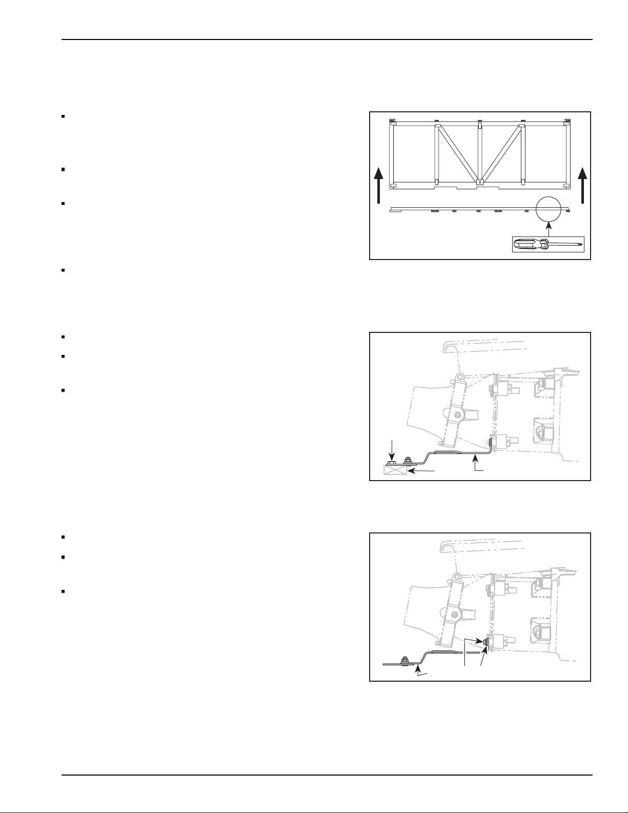
UNCRATING...................................... 3
Crate Cover.......................................... 3
Lifting the watercraft............................... 3
Shipping Bracket.................................... 3
SET-UP............................................. 4
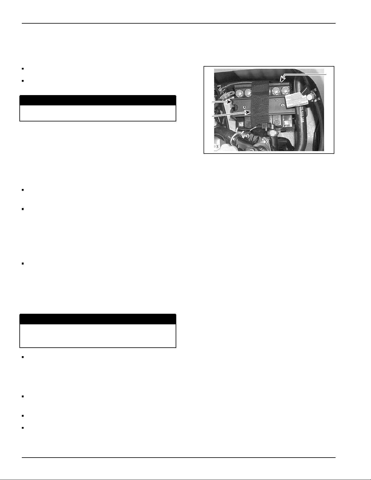
Battery Preparation................................. 4
Battery Installation ................................. 4
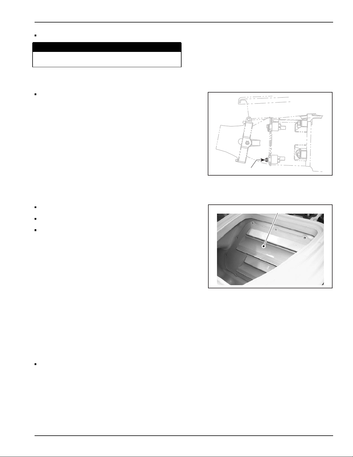
Venturi ............................................... 5
Access Door ........................................ 5
FINAL PREPARATION........................... 5
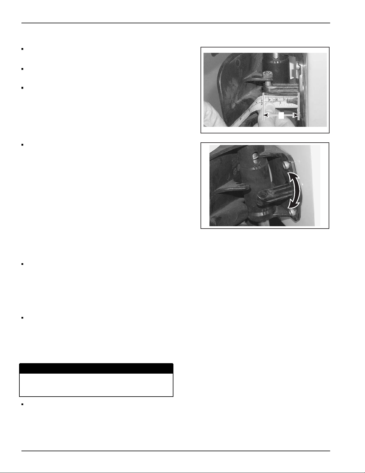
Steering Alignment................................. 5
O.P.A.S. System Alignment....................... 6
Recommended Fuel ............................... 6
Fuel System Pressurization ....................... 7
Coolant Level ....................................... 7
Watercraft Identification........................... 8
Programming Keys With B.U.D.S. ............... 9
Oil..................................................... 9
Ending a B.U.D.S. Session.......................10
Throttle Cable......................................11
FINAL INSPECTION............................12
General Instructions...............................12
DELIVERY TO CUSTOMER...................12
Decal Protective Films............................12
Cleaning the Watercraft ..........................12
General Instructions...............................13
Fuel System........................................13
Handlebar Tag......................................13
Break-In Period ....................................13
SPECIFICATIONS ...............................14
Technical Data .....................................14
Printed in Canada (sbl2004-002 DR) 2004-1 1 / 15
®™Trademarks of Bombardier Inc. or its subsidiaries.
©2003 Bombardier Inc. All rights reserved.

IMPORTANT NOTICE 4–TECSCModels
IMPORTANT NOTICE
This bulletin must be used in conjunction with the Predelivery Check List enclosed in the shrink pack.
WARNING
To obtain limited warranty coverage, predelivery procedures must be performed by an authorized
Sea-Doo watercraft dealer/distributor. Apply all necessary torques as indicated.
N
NN
NO
OO
OT
TT
TE
EE
E:
::
:The information and components/system descriptions contained in this document are correct at
the time of publication. Bombardier however, maintains a policy of continuous improvement of its products
without imposing upon itself any obligation to install them on products previously manufactured. Due to
late changes, there might be some differences between the manufactured product and the descriptions
and/or specifications in this document. Bombardier reserves the right at any time to discontinue or change
specifications, designs, features, models or equipment without incurring obligation. The illustrations in
this document show the typical construction of the different assemblies and may not reproduce the full
detail or exact shape of the parts. However, they represent parts that have the same or similar function.
The content of this bulletin is designed as a guideline only. All mechanics performing predelivery
procedures should have attended the current model year service training. Further information or inquiries
should be directed to your distributor service representative and/or specific Shop Manual sections. Please
complete the Predelivery Check List for each watercraft and retain a customer signed copy. Make sure
the customer receives the Operators Guide,Predelivery Check List signed copy and Safety Videocassette.
2 / 15 2004-1 Predelivery

4–TEC SC Models UNCRATING
UNCRATING
Crate Cover
1
22
F00A2A6
Carefully lay the crate on its bottom.
CAUTION: Allowing the crate to drop may cause
serious damage to the watercraft.
Using a drill or a screwdriver, remove all screws
[
[[
[1]
]]
] retaining crate cover to crate base.
Assisted by another person, lift up crate cover [
[[
[2]
]]
].
N
NN
NO
OO
OT
TT
TE
EE
E:
::
:Do not tip cover toward the front or back of
the watercraft. Raise cover vertically [
[[
[2]
]]
]fromboth
ends at the same time.
Remove parts from the watercraft’s rear storage
compartment.
Lifting the watercraft
1
32
F08A056
Cut strapping at watercraft front eyelet.
Release [
[[
[1]
]]
] the shipping bracket [
[[
[2]
]]
] at the rear of
the watercraft from the crate base [
[[
[3]
]]
].
Lift the watercraft using the appropriate lift kit and
install it on a proper support.
Shipping Bracket
1 32
F08A066
Remove the shipping bracket [
[[
[1]
]]
] from the venturi.
Discard the shipping bracket and the hexagonal
bolts [
[[
[2]
]]
].
Keep the flat washers [
[[
[3]
]]
].
Predelivery 2004-1 3 / 15

SET-UP 4–TECSCModels
SET-UP
Battery Preparation
1
2
3
F18H1F6
Unscrew the battery bracket [
[[
[1]
]]
].
Using strap [
[[
[2]
]]
], lift the battery [
[[
[3]
]]
] out of the
watercraft.
WARNING
Do not charge the battery while installed in
the watercraft.
N
NN
NO
OO
OT
TT
TE
EE
E:
::
:Refer to last year Bombardier Sea-Doo
Shop Manual for the activation of a new battery.
Battery Installation
Install the battery in the battery support in the
engine compartment.
Secure the RED positive cable to the battery
positive post with:
- 1 hexagonal bolt from section no. 1 of predelivery
kit.
- 1 flat washer from section no. 1 of predelivery kit.
- 1 nut from section no. 1 of predelivery kit.
Secure the BLACK negative cable to the battery
negative post with:
- 1 hexagonal bolt from section no. 1 of predelivery
kit.
- 1 flat washer from section no. 1 of predelivery kit.
- 1 nut from section no. 1 of predelivery kit.
WARNING
Always connect the battery cables exactly in this
specific order. Connect RED positive cable first,
then the BLACK negative ground cable.
Secure the battery with:
- Bracket (previously removed).
- 2 flat washers (previously removed).
- 2 nuts (previously removed).
Apply dielectric grease (P/N 293 550 004) on
battery posts.
Cover battery positive post with rubber boot.
Remove the plastic red cap from the battery
vent elbow.
4 / 15 2004-1 Predelivery

4–TEC SC Models SET-UP
Install the battery vent tube.
WARNING
Ensure vent tube is not kinked or obstructed.
Battery vent tube must be properly installed.
Venturi
1
F08A076
Secure the lower portion of the venturi [
[[
[1]
]]
]with:
- 2 hexagonal bolts from section no. 1 of
predelivery kit.
- 2 lock washers from section no. 1 of predelivery
kit.
- Two 8 mm flat washers (previously removed).
Torque to 21 N•m(15 lbf•ft).
Access Door
1
F02L3X7
Open the front storage compartment cover.
Remove the storage tray.
Secure the access door [
[[
[1]
]]
]with:
- 7 plastic darts from section no. 2 of predelivery
kit.
- 4 plastic darts are already in place.
FINAL PREPARATION
Steering Alignment
N
NN
NO
OO
OT
TT
TE
EE
E:
::
:All adjustments have already been
performed at the factory. If readjustments is
needed, the following procedures should be used.
Check steering alignment as per procedure in the
appropriate Sea-DooShopManual.
Predelivery 2004-1 5 / 15

FINAL PREPARATION 4–TECSCModels
O.P.A.S. System Alignment
A
F18K046
This watercraft is equipped with the Off-Power
Assisted Steering system (O.P.A.S.).
While steering is aligned square with the hull,
adjust the O.P.A.S. system.
Vane stem must be 42 mm (1 5/8 in) [
[[
[A]
]]
]outof
bracket, see photo.
F18K056
If this measure is wrong, remove side vane bolt
and screw/unscrew vane stem until the right
measure is obtained.
Recommended Fuel
Fuel type:
-RECOMMENDED: Premium unleaded gasoline
with 91 octane (RON + MON)/2 specification for
optimum performance.
-MINIMUM: Regular unleaded gasoline with 87
octane (RON + MON)/2 specification.
At predelivery, we suggest dealers to fill the
fuel tank.
N
NN
NO
OO
OT
TT
TE
EE
E:
::
:Do not add oil into the fuel.
CAUTION: Never use fuel containing more than
10% alcohol (ethanol or methanol).
WARNING
Fuel is flammable and explosive under certain
conditions. Always work in a well ventilated
area.
It might be necessary to remove and install
the safety lanyard 2 or 3 times to initially feed
the fuel system.
6 / 15 2004-1 Predelivery

4–TEC SC Models FINAL PREPARATION
N
NN
NO
OO
OT
TT
TE
EE
E:
::
:This procedure should be explained to
customer at delivery.
N
NN
NO
OO
OT
TT
TE
EE
E:
::
:Verify fuel line connectors prior to
powering-up the MPEM. This verification must be
done visually as well as manually by physically
checking each connection.
WARNING
Never install the safety lanyard prior to check
fuel line connector tightness.
Fuel System Pressurization
WARNING
At PDI, whenever doing any type of repair on
the watercraft or if any components of the fuel
system are disconnected, a pressure test must
be done before starting the engine. Ensure
to verify fuel line ends for damage. Always
cut-away damaged end before reinstallation.
For fuel system pressure test procedure, refer to
last year Bombardier Sea-Doo Shop Manual.
Coolant Level
1
F18E0M6
WARNING
Check coolant level with engine cold. Never add
coolant in cooling system when engine is hot.
Remove seat extension to expose cooling system
expansion tank [
[[
[1]
]]
].
Predelivery 2004-1 7 / 15

FINAL PREPARATION 4–TECSCModels
1
F18E0N6
With vehicle on a level surface, liquid should
be between MIN. and MAX. level marks [
[[
[1]
]]
]of
coolant reservoir when engine is cold.
N
NN
NO
OO
OT
TT
TE
EE
E:
::
:The watercraft is level when it is in water.
When on a trailer, raise trailer tongue and block in
this position when bumper rail is level.
Add coolant to have the level between marks as
required.
Use a funnel to avoid spillage.
Do not overfill.
N
NN
NO
OO
OT
TT
TE
EE
E:
::
:Use a blend of 50% antifreeze with 50%
water. Premixed antifreeze/water is available
(P/N 293 600 038).
Properly reinstall and tighten filler cap then
reinstall seat extension.
Watercraft Identification
To enter the watercraft identification or to program
a safety lanyard, use Bombardier Utility and
Diagnostic Software (B.U.D.S.) in conjunction
with the VCK.
N
NN
NO
OO
OT
TT
TE
EE
E:
::
:Make sure to use B.U.D.S. version G2.0.0
or higher and take note of the following details:
- Version G2.0.1 of B.U.D.S. is now available
on BOSSWeb
- Version G2.0.1 of B.U.D.S. is not availableonCD
- Installing version G2.0.1 of B.U.D.S. will not
require a new access code as version G2.0.0 did
if it is put in the same directory as G2.0.0 was
- Version G2.0.0 of B.U.D.S. will still work fine for
programming this Sea-Doo model
F18R0D6
N
NN
NO
OO
OT
TT
TE
EE
E:
::
:There are a few upgrades on Version
G2.0.1, including a function that automatically saves
each MPEM document when read from a vehicle.
The document will be saved in the same directory
as the B.U.D.S. program was saved in. See photo.
8 / 15 2004-1 Predelivery

4–TEC SC Models FINAL PREPARATION
1
2
F16R016A
Connect VCK components and start B.U.D.S.
Choose KW2000 Protocol from Choose Protocol
option in the MPI drop-down menu [
[[
[1]
]]
].
Read MPEM using leftmost icon [
[[
[2]
]]
].
Click on VEHICLE tab.
Enter customer name in the CUSTOMER field.
Click on the second icon of the toolbar Write
MPEM to register new informations from MPI
memory to MPEM.
Programming Keys With B.U.D.S.
21
F12R1P6A
Click on KEYS tab.
If the key to be added is a normal key (yellow
key), click on ADD NORMAL KEY [
[[
[1]
]]
]button
on bottom of screen.
If the key to be added is a Sea-Doo Learning Key
(whitekeywithSea-DooLKwrittenonit),click
on ADD LEARNING KEY [
[[
[2]
]]
] button on bottom
of screen.
N
NN
NO
OO
OT
TT
TE
EE
E:
::
:This key limits vehicle top speed to
approximately 55 km/h (35 mph).
Install key on MPI DESS post.
A new key is now saved in the computer.
Ensure to save new data in MPEM using WRITE
MPEM button.
WARNING
Never use a Sea-Doo LK (Sea-Doo Learning
Key) as a regular key.
Oil
Use Bombardier 5W-40 synthetic oil
(P/N 293 600 039) or a mineral based 10W-40
motor oil.
Engine is factory filled with oil.
Verify oil level using the following procedure:
- Install a garden hose to the flushing connector.
N
NN
NO
OO
OT
TT
TE
EE
E:
::
:Refer to FLUSHING in POST-OPERATION
CARE (Operator’s Guide) and follow the procedure.
Predelivery 2004-1 9 / 15

FINAL PREPARATION 4–TECSCModels
CAUTION: If watercraft is not on water area,
make sure to cool engine using flush kit,
otherwise, the engine and/or the exhaust system
may be severely damaged.
- Warm-up engine then let idle for 30 seconds
before stopping.
- Stop engine.
-Wait at least 30 seconds then pull dipstick
out and wipe clean.
WARNING
Engine oil may be hot. Certain components in
the engine compartment may be very hot. Direct
contact may result in skin burn.
CAUTION: Never run engine longer than 5
minutes. Drive line seal has no cooling when
watercraft is out of water.
1
3
2
F18D2N6
- Reinstall dipstick, push in completely.
- Remove dipstick and read oil level. It should be
between marks [
[[
[3]
]]
].
•Mark [
[[
[1]
]]
]forFULL.
•Mark [
[[
[2]
]]
]forADD.
- Otherwise, add up oil to have the level between
marksasrequired.
1
F18D086
- To add oil, unscrew oil cap [
[[
[1]
]]
]. Place a funnel into
the opening and add the recommended oil to the
proper level. Do not overfill.
- Properly reinstall oil cap and dipstick.
Ending a B.U.D.S. Session
Click on FAULT tab and check if there are active
faults.
If so, service watercraft then clear the faults in
B.U.D.S.
10 / 15 2004-1 Predelivery

4–TEC SC Models FINAL PREPARATION
IMPORTANT: After a problem has been solved,
ensure to clear the fault(s) in the MPEM using
the VCK. This will properly reset the appropriate
counter(s). This will also records that the problem
has been fixed in the MPEM memory.
Click on WRITE MPEM button to transfer new
settings and information.
Click on EXIT button (rightmost) to end session.
Ensure to reinstall the cap over the communication
connector.
Throttle Cable
1
F01K086
Verify the adjustment of the throttle cable as
follows:
- Throttle lever [
[[
[1]
]]
] must reach handlebar grip
without causing strain to cable or cable bracket.
- With the throttle lever in full throttle position, the
throttle lever stopper should almost contact the
throttle body.
- To verify that there is free play, apply a light
pressure on the throttle plate(s), a slight play
should be obtained.
- With the throttle lever released, it must have a
free play of 0.5 - 4 mm (1/64 - 5/32 in) in the cable.
CAUTION: Improper cable adjustment will cause
strain on cable and/or damage cable bracket
or throttle lever at handlebar.
12
F18F076
To adjust throttle cable, loosen jam nut [
[[
[2]
]]
]then
turn the adjustment nut [
[[
[1]
]]
] as necessary.
WARNING
Make sure idle speed screw contacts throttle
cam when throttle lever is fully released at
handlebar.
CAUTION: Never attempt to adjust the idle speed
through the throttle body tamper proof screw.
If so, it would impair the idle speed stability.
Besides, no adjustment could be performed
by the dealer nor the factory to correct the
idle speed. The throttle body would need to
be replaced. Also take into account that might
change the engine emission level and the engine
might not meet the EPA/CARB requirements.
For more informations on throttle cable adjustment,
refer to last year’s Bombardier Sea-Doo Shop
Manual.
Predelivery 2004-1 11 / 15

FINAL INSPECTION 4–TECSCModels
FINAL INSPECTION
General Instructions
Inspect, if applicable, the movement/operation of:
- steering and jet pump nozzle
- reverse mechanism
- throttle lever
- monitoring beeper
- start/stop button
- DESS system
- safety lanyard switch
- speedometer
-InfoCenter.
Verify tightness of all water hoses and clamps at
jet pump and engine.
Complete Predelivery Check List.
Test run watercraft.
DELIVERY TO CUSTOMER
Decal Protective Films
N
NN
NO
OO
OT
TT
TE
EE
E:
::
:Protective film on decals must be removed.
Slowly peel off protective films covering all decals.
Cleaning the Watercraft
Clean watercraft.
CAUTION: Clean apparent fiberglass and plastic
partswithacleanclothandsoapywateror
isopropyl alcohol. Never use strong detergent,
degreasing agent, paint thinner, acetone, etc. Do
not apply isopropyl alcohol directly on decals.
12 / 15 2004-1 Predelivery

4–TEC SC Models DELIVERY TO CUSTOMER
General Instructions
Explaintocustomer:
- Operator’sguide
- Watercraft operation
- Maintenance
- Safety features
- On-product labels
-Warranty
- Where possible, give a brief demo ride and
explain watercraft operation.
Explain, complete and return:
- The WARRANTY REGISTRATION CARD (legal
requirement).
Give to customer:
- Operator’sguide
- Safety videocassette
-AskthecustomertosignthePredelivery
Check List.
Fuel System
This procedure should be explained to the
customer:
- It might be necessary to remove and install
the safety lanyard 2 or 3 times to initially feed
the fuel system.
Handlebar Tag
N
NN
NO
OO
OT
TT
TE
EE
E:
::
:A tag is tied to the handlebar. Let it in place
until delivery and make sure purchaser reads it.
Break-In Period
With Sea-Doo watercraft powered by Rotax®
engines, a break-in period of 10 hours is required
before continuous operation at full throttle. To
achieve a good break-in, vary the engine speed
every few minutes with brief wide open throttle
accelerations of up to 15 seconds. Continued wide
open throttle runs and prolonged cruising without
speed variations should be avoided, this can cause
engine damage during the break-in period.
N
NN
NO
OO
OT
TT
TE
EE
E:
::
:Never add oil in fuel tank during break-in
period.
Predelivery 2004-1 13 / 15

SPECIFICATIONS 4–TECSCModels
SPECIFICATIONS
Technical Data
MODEL GTX 4–TEC SUPERCHARGED
E
EE
EN
NN
NG
GG
GI
IIIN
NN
NE
EE
E
Engine Type 1503 SC
Number of Cylinder 3
Induction Type Mechanically-driven supercharger
Engine Revolution Limiter Setting ±50 RPM 7650
Intake Valve 2 x 38 mm per cylinder
Exhaust Valve 2 x 31 mm per cylinder
Lubrication 10W-40 motor oil (or equivalent)
F
FF
FU
UU
UE
EE
EL
LL
LS
SS
SY
YY
YS
SS
ST
TT
TE
EE
EM
MM
M
Fuel Injection Type Multiport sequential,
throttle body (52 mm)
Idle Speed (in water) ±50 RPM 1800
Throttle Position (TPS) 1.6 k 2.4 k
Crankshaft Position (CPS) 190 290
Manifold Air Temperature (MATS) 2.280 k 2.740 k @ 20C
Water Temperature (WTS) 2.280 k 2.740 k
Manifold Air Pressure (MAPS)
6040 (terminals 2-1)
5554 (terminals 3-2)
5822 (terminals 3-1)
Sensors Typical Resistance
Exhaust Gas Temperature (EGTS) 2.280 k 2.740 k
Fuel Injector 11.4 12.6 @ 20C
Gas Grade/Pump Octane Number (R + M)/2
RECOMMENDED: PREMIUM unleaded gasoline with
91 octane specification for optimum performance
MINIMUM: REGULAR unleaded gasoline
with 87 octane specification
E
EE
EL
LL
LE
EE
EC
CC
CT
TT
TR
RR
RI
IIIC
CC
CA
AA
AL
LL
L
Ignition System Type Digital, inductive type
Make and type DCPR8ES
Spark plug
Gap 0.7 - 0.8 mm (0.028 - 0.031 in)
Ignition Timing BTDC Non adjustable timing
14 / 15 2004-1 Predelivery

4–TEC SC Models SPECIFICATIONS
MODEL GTX 4–TEC SUPERCHARGED
P
PP
PR
RR
RO
OO
OP
PP
PU
UU
UL
LL
LS
SS
SI
IIIO
OO
ON
NN
N
Propulsion System BOMBARDIER Formula pump
Jet Pump Type Axial flow single stage
Transmission Direct drive
Jet Pump Grease Type Thermalube XL-OL-C2, NLGI2
Steering Nozzle Pivoting Angle 0° to 20°
Minimum Required Water Level 90 cm (35 in)
Outside Diameter 155.3 mm (6.115 in)
Impeller
Material Stainless steel
L
LL
LI
IIIQ
QQ
QU
UU
UI
IIID
DD
DS
SS
S
Fuel Tank Capacity [1] L (U.S. gal.) 60 (15.9)
Oil Injection Tank Capacity L (U.S. gal.) 4.5 (1.2) for a dry engine
3.0 (0.8) after first oil change
Impeller Shaft Reservoir Capacity mL (U.S. oz)
10 (0.34) at front of bearing,
50 (1.7) at rear of bearing,
50 (1.7) at pump cap
- [1] Including reserve.
Predelivery 2004-1 15 / 15
Table of contents
Other Sea-doo Marine Equipment manuals
Popular Marine Equipment manuals by other brands

E2S
E2S BE S120D Series instruction manual

Raymarine
Raymarine SmartPilot ST8002 operating guide

Eddystone
Eddystone EC10A2/1 Installation notes

Furuno
Furuno FMD-3200 Operator's manual

INIM Electronics
INIM Electronics Air2 Series Installation and programming manual

Sterling
Sterling Hyfire HFW-BS-05 quick start guide

PYI
PYI Max-Prop EASY 2 Blade instruction manual

Veethree
Veethree EGM installation guide

Raymarine
Raymarine hsb2 PLUS Series Owner's handbook

Yacht Controller
Yacht Controller MAXIMO ONE user manual

ComNav
ComNav Commander P2 Quick reference guide

Teleflex Marine
Teleflex Marine SeaSTAR OPTIMUS Steering System user manual