PYI Max-Prop EASY 2 Blade User manual

EASY SAILDRIVE
INSTRUCTION MANUAL
2, 3, & 4 BLADES
WWW.MAX-PROP.COM
Quality Marine
Equipment Since 1981
For installation videos visit
our website.

INTRODUCTION
Thank you for having chosen a Max-Prop automatic feathering propeller for your vessel. This
instruction booklet is designed to answer all your questions on installation and use of the Max-
Prop. Please read he instructions carefully and verify the correct working of the propeller before
installing it on your boat.
IMPORTANT NOTES
The propeller is shipped already assembled (unlike Classic Max-Prop models). The rotation (left
or right hand) and pitch has been determined at the time of the order and is therefore ready
to be tted on the shaft. Please note that Max-Prop parts are NOT interchangeable so make
sure that if you receive more than one propeller (for a catamaran for example) you do NOT
interchange parts.
WHATS INCLUDED
x2
Shaft Nut Lock Screws x3
Zinc Bolt
x1
Center Locking Bolt
x1
Grease Fitting x1 or 2
Grease Plug
x1
Set Screw For
Locking Bolt
1
x2
Pitch Locking Screw x2
Pitch Adjustment Bolt x2
Zinc Anode x1
Shaft Nut
x1

INSTRUCTIONS
1. Fit the propeller onto the propeller shaft, just like a xed propeller. Be sure that the thrust
washer is on the spline before tting the Max-Prop onto the spline. Without the thrust
washer the propeller will be loose fore and aft on the spline, and will damage the SailDrive
or propeller.
2. Tighten the nut onto the spline. Align the holes in the back of the nut with the groves in
the central hub, so that the two shaft nut lock screws can be tightened in place. Insert and
tighten the center locking bolt into the back of the nut. Secure it with the set screw for the
center locking bolt.
3. Fit the zinc and secure it with the three allen bolts. Make sure that the zinc and the
propeller are clean to insure good contact.
4. Fill the prop with marine grease (supplied) using a grease tting (supplied) inserted into the
grease holes on the side of the propeller marked “GREASE”. The Max-Prop Easy propeller
works properly only if the central body is completely lled with the correct grease. Verify
that the grease is oozing from the rotating joints between the central part and the hub, so
that all of the moving surfaces are perfectly greased. The grease used must be a type of
grease approved by Max-Prop so it will remain uid after years of use and will not get too
sti in cold water. Follow steps 4.1 through 4.9 on page 3. We recommend Lubriplate 130AA
calcium based grease.
TIP: Watch our YouTube video on how to grease a
propeller, visit https://youtu.be/Pr_aEJgugjM
Or scan the QR code with a mobile device.
Thread Diameter Torque in Ft/lbs
16mm 50 ft. lbs.
20mm 60 ft. lbs.
2
Fig.1
Spline
Thrust Washer
Prop
Shaft Nut
Pitch Adjustment Bolt
Set Screw For Locking Bolt
Zinc Bolt
Shaft Nut Locking Screws
Center Locking Bolt
Zinc Anode

G
R
E
A
SE
GREASE
GREASE
GREASE
* Repeat these steps with the forward tting.
GRE
A
SE
GREASE
GREASE
GREASE
GREASE
GREASE
GR
E
A
SE
GREASE
GREASE
GREASE
GREASE
GREASE
GREASE
GREASE
4.1
4.4
4.7
4.2
4.5
4.8
4.3
4.6
4.9
3

5. Conrm that in the feathered position the blades look like the Fig.2 below.
6. Before launching the boat, it is absolutely necessary to operate as follows:
• Hold the propeller shaft.
• Check that the blades of the propeller rotate freely from the forward to the reverse
position just by a light eort.
• In the feathered position the blades must be perfectly lined up and set like Fig. 2.
• Conrm that the propeller body is full of grease
• Make sure that the propeller is protected from galvanic corrosion by using zinc anodes
on the propeller and the shaft.
PITCH ADJUSTMENT
The pitch on a Max-Prop changes according to the diameter and the blades rotation angle.
Fig.3 below shows the pitch in inches corresponding to the degree of blades angle for a given
propeller diameter.
Yes No!
Fig.2
PROPELLER DIAMETER
12” 13” 14” 15” 16” 17” 18” 19” 20” 21” 22” 23” 24” 25” 26”
BLADE ANGLE
10º 4 4.3 4.6 4.9 5.2 5.5 6 6.3 6.7 7.1 7.4 7.7 8 8.3 8.6
12º 4.8 5.2 5.6 6 6.4 6.8 7.2 7.6 8 8.4 8.8 9.2 9.6 10 10.4
14º 5.6 6 6.6 7.1 7.6 8 8.4 8.8 9.4 9.8 10.4 10.8 11.2 11.6 12.2
16º 6.4 6.9 7.6 8.1 8.6 9.1 9.8 10.3 10.8 11.3 12 12.5 13 13.5 14
18º 7.2 7.8 8.6 9.2 9.8 10.4 11 11.5 12.1 12.8 13.4 14 14.6 15.2 16
20º 8.2 8.9 9.6 10.3 11 11.6 12.4 13 13.7 14.5 15 15.6 16.4 17 17.8
22º 9.2 10 10.7 11.4 12.2 12.9 13.6 14.3 15.1 16 16.8 17.5 18.2 18.9 19.8
24º 10 10.9 11.8 12.5 13.4 14.2 15 15.8 16.8 17.6 18.4 19.2 20.2 21 21.8
26º 11 12 12.8 13.8 14.7 15.7 16.6 17.4 18.4 19.3 20.2 21 22 22.9 23.8
28º 12 13 13.9 15 16 17 18 18.9 20 21 22 23 24 25 26
30º 13 14 15.1 16.2 17.3 18.5 19.6 20.6 21.7 22.8 24 25 26.1 27.3 28.2
Fig.3
4
Max-Prop Easy and Whisper models are supplied with 5 dierent forward pitch screws (16° to
24° in 2° increments) as well as 3 reverse pitch screw (16° to 24° in 4° increments)

INCHES OF PITCH
Diameter and pitch must be
calculated as if Max-Prop Easy was
a normal xed propeller. Max-
Prop Easy then oers the great
advantage of pitch adjustability in
order to optimize the performance
of the propeller. If the engine does
not reach the desired RPM, reduce
the blade angle; on the contrary,
if the engine exceeds the desired
RPM, increase the blade angle.
The Max-Prop Easy allows an angle
variation of 2° increments, this
corresponds to a variation in the
engine RPM of about 13% at the
same boat speed. It’s possible
to change either the pitch to optimize the engine performance, or the rotation (for ex. if you
change the engine, or if there was a mistake when ordering the prop). If you have doubts about
the rotation: shaft rotation is determined from the stern of the boat looking forward. With the
engine in forward position clockwise rotation of the propeller means it is right hand “R”, and a
counterclockwise rotation is a left hand “L”.
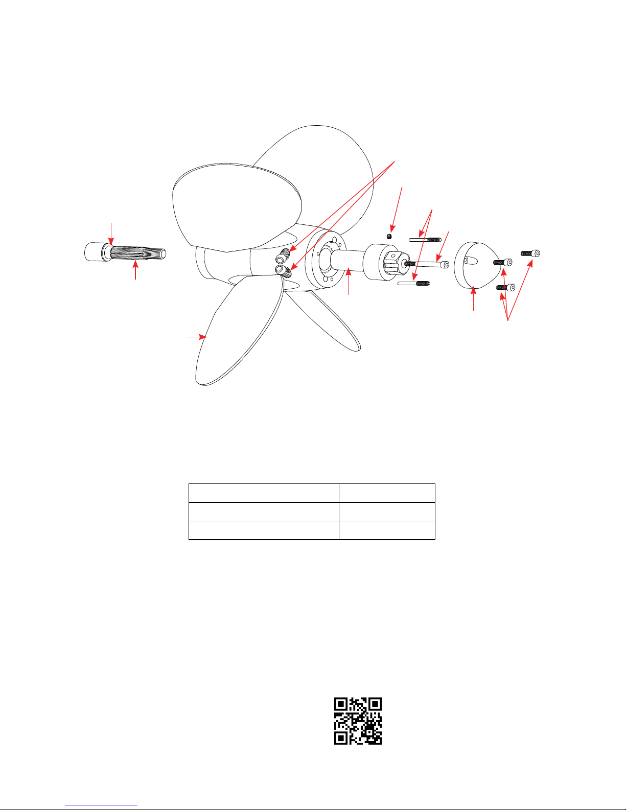
Pitch and rotation of the Max-Prop Easy can be changed as follows:
On the body of the propeller are two threaded bores, marked with letters “R” and “L”; within
these bores are placed two bolts.
The pitch of the propeller, both in forward and reverse position, can be easily varied by changing
the supplied bolts threaded into the body of the propeller with other bolts of a dierent length.
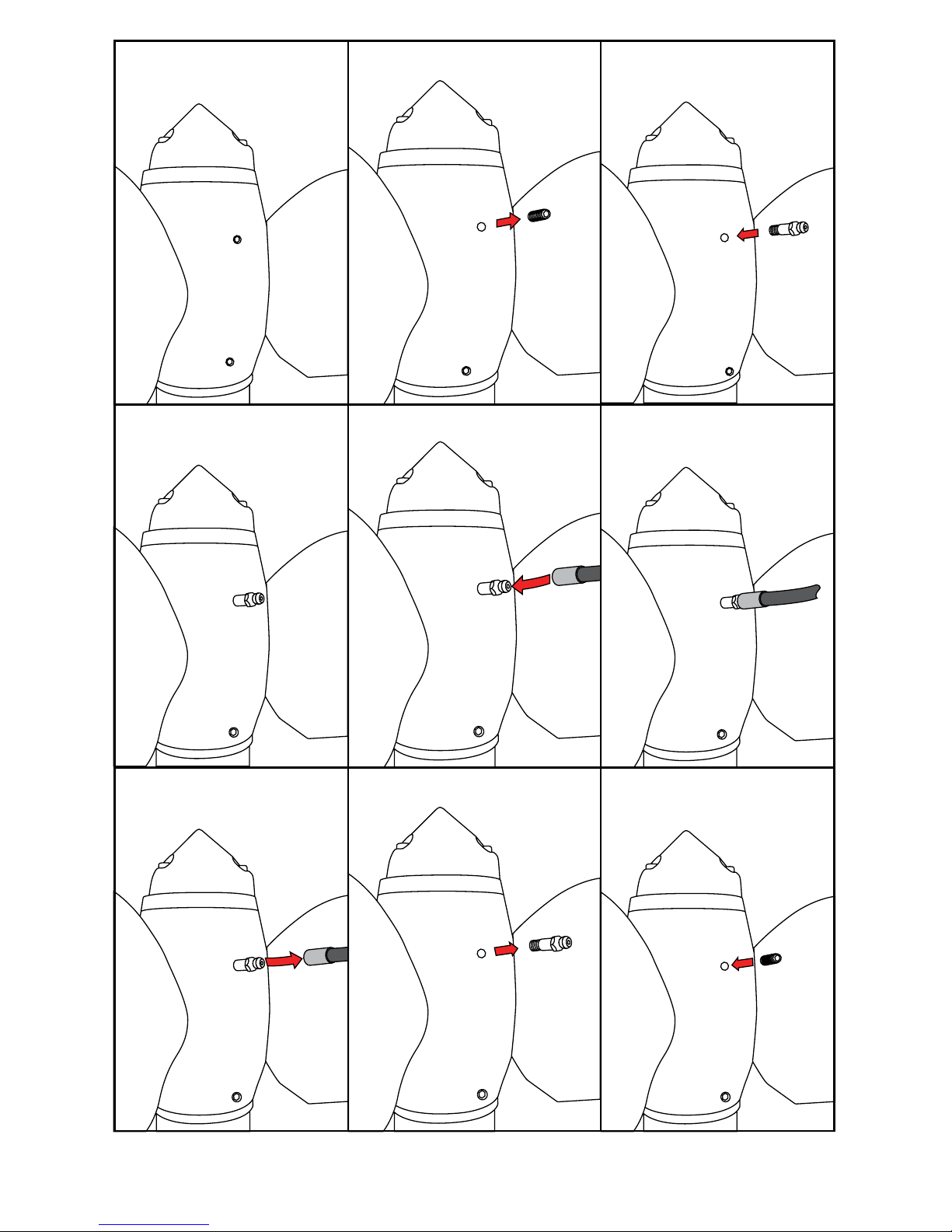
The pitch in forward rotation varies by changing the bolts placed in bore “R” if the propeller is
right-handed or changing the bolts placed in bore “L” if the propeller is left-handed. The list of
the pitch regulation bolts, that are supplied with every Easy propeller is indicated in g.4.
For example inserting the #20 bolt in the forward rotation and 2 in the reverse rotation will
provide a 20° angle for both front position and reverse rotation. Varying 1mm the length of the
bolts, blades inclination has a 2° variation
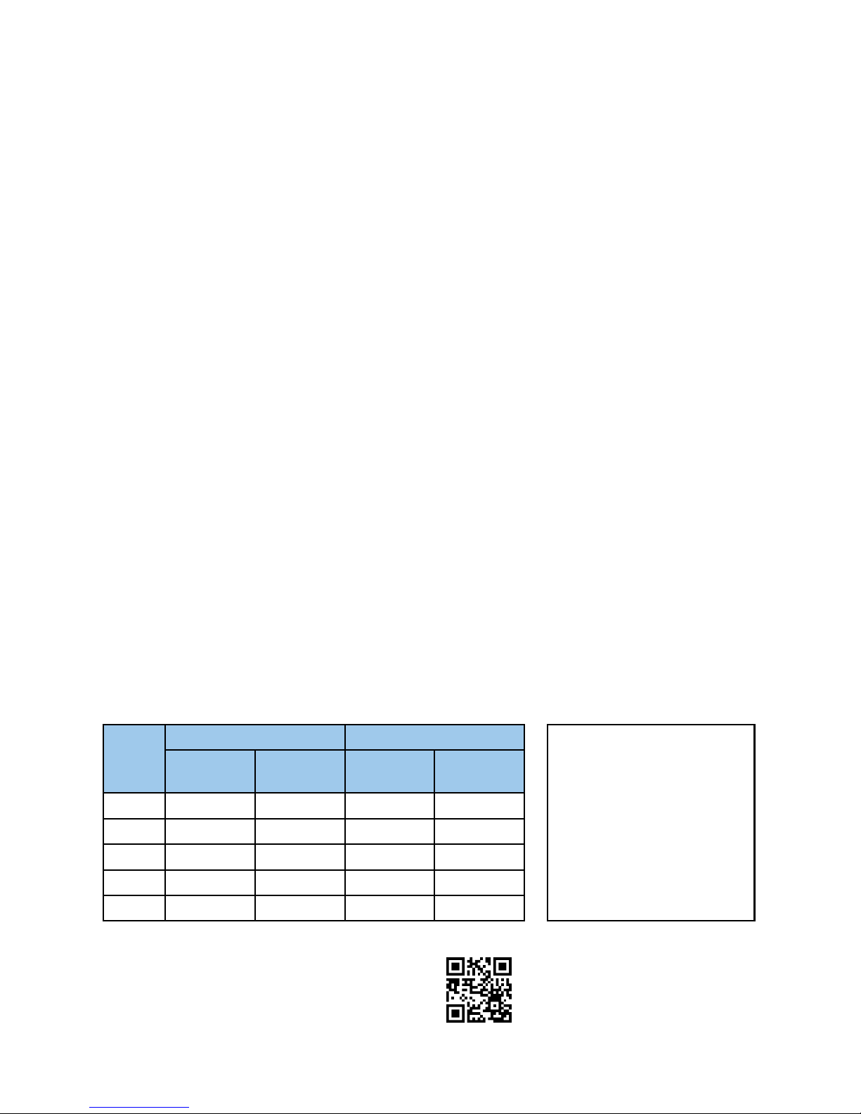
Blade
Angle
Right Rotation Left Rotation
Forward
Bore “R”
Reverse
Bore “L”
Forward
Bore “L”
Reverse
Bore “R”
16° 16 1 16 1
18° 18 18
20° 20 220 2
22° 22 22
24° 24 3 24 3
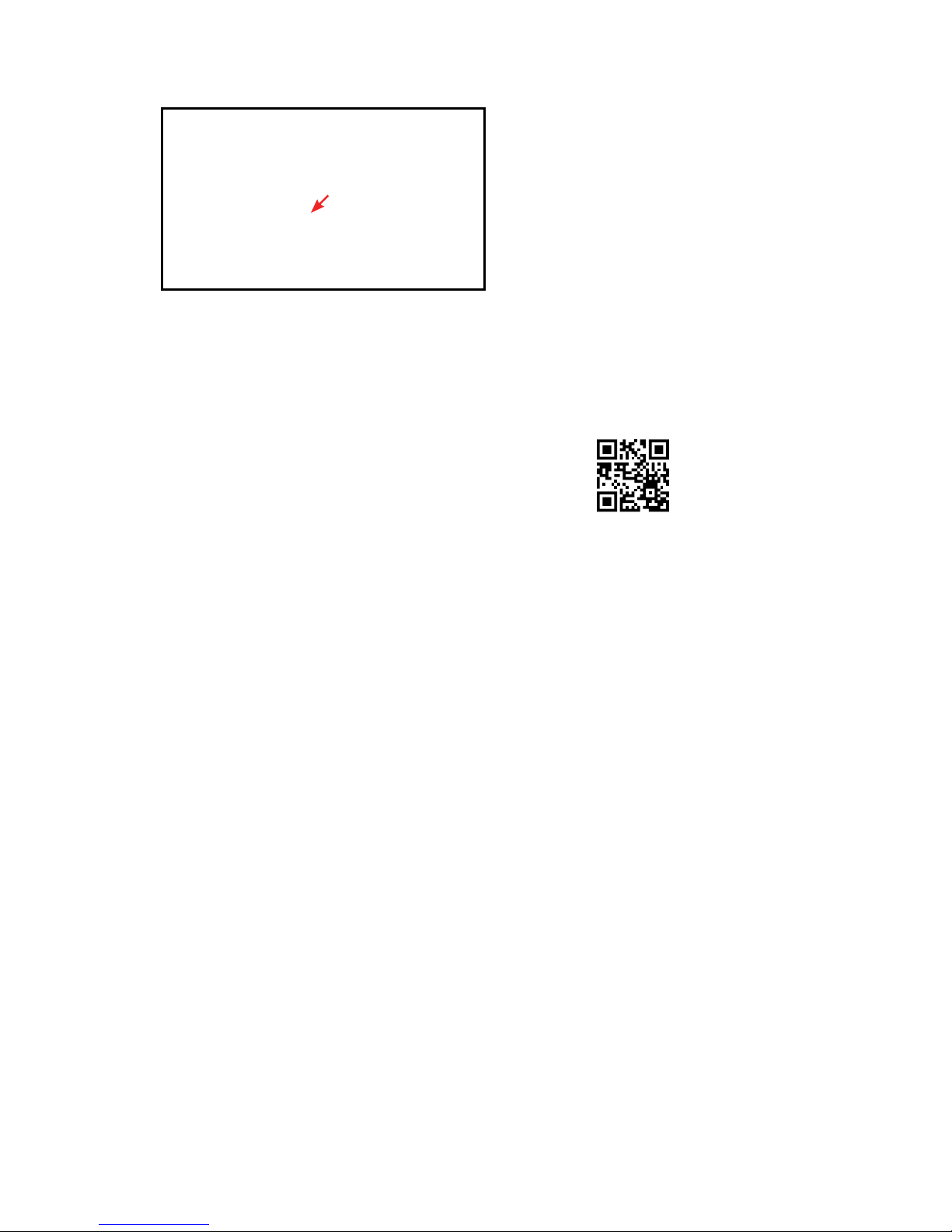
Fig.5 - Close up of the Left and
Right pitch adjustment bolts.
Fig.3b
Fig.4
5
TIP: Watch our YouTube video on how to adjust
the pitch, visit https://youtu.be/HJsnHCi2U6U
Or scan the QR code with a mobile device.

With the Max-Prop Easy it is also possible to change the rotation, e.g. if you change the engine,
or if there was a mistake when ordering the prop. If you have doubts about the shaft rotation,
it can be determined looking forward from the stern of the boat. With the engine in forward
position a clockwise rotation of the propeller means it is right handed(R), and a counter-
clockwise rotation is left handed (L).
In order to change the rotation of the Max-Prop Easy, from a right hand rotation to a left hand
rotation or vice versa do as follows, referring to Fig.6.
1. Place the propeller in the feathered position. Unscrew the locking-zinc screws, and
remove the zinc.
2. Unscrew the locking-nut screws and remove the nut.
3. Remove the Circlip on the aft edge of the hub.
4. Be sure the propeller is in the feathered position, then release the zinc-bearing ring.
5. Once released the zinc-bearing ring, you see that on one tooth of the hub (the aft side)
there is a reference mark, and a tooth of the bearing-zinc ring are marked one with “L” and
the other with “R”.
CHANGING THE ROTATION
6
R L
Shaft Nut
Zinc Bearing Ring
Shaft Locking Bolt
Ring
Mark
Zinc Bolt
Zinc Anode
Fig.6

7
6. If you place the zinc bearing ring in its seat again, matching the “L” tooth with the hub
reference mark, you have a left hand rotating propeller, on the contrary, with the “R” tooth
you have a right rotating propeller as in Fig.6.
7. Replace the “Circlip” in to its seat.
8. Tighten the nut and secure it with the locking-nut screws.
9. Place the zinc again, and secure it with the 3 proper screws.
10. Be sure to change the pitch setting bolts to reect the pitch setting for the new
rotation.
TIP: Watch our YouTube video on how to change the rotation,
visit https://youtu.be/HJsnHCi2U6U. Or scan the QR code.
PROPELLER USE
The Max-Prop EASY works automatically. By putting the transmission in gear the blades will
engage in either forward or reverse (WARNING: do not change from forward to reverse and
vice versa when the engine is running at high RPM) and feathers from forward position
when you turn o the engine and lock the shaft.
The best way to feather the propeller is:
• Power at 2 to 3 knots in forward.
• Kill the engine while still engaged in forward.
If your propeller has been greased properly it will feather in a fraction of a second as soon as
you stop the shaft from freewheeling. DO NOT kill the engine while in reverse. In this case the
blades will be in the reverse position and cannot feather. You can actually use this feature to
drive a shaft alternator, or regenerate with an electric motor.
Modern transmissions are either mechanical or hydraulic. With a mechanical transmission, the
best way to stop the shaft freewheeling is to engage the transmission in reverse (WARNING:
engage the reverse only after the engine has stopped completely). With a hydraulic
transmission you must shut o the engine while still engaged in forward. The remaining
hydraulic pressure will in eect lock the shaft for a few moments, enough for the Max-Prop to
feather.
MAINTENANCE
• The propeller must always be completely lled with recommended Lubrilate 130AA grease.
The propeller should be greased at least once a year. This can be done with the boat in or
out of the water.
• Make sure that you always keep the zinc anodes in good condition. They must be replaced
at least once a year, even if they still look ok. The propeller must be protected by a lot
of zinc, so also use a zinc on the shaft when possible. When replacing it make sure that
you clean the surfaces between the zinc and the propeller shaft in order to have a good
electrical contact.

WARNING
It is important to follow the instruction below carefully so as to avoid a shock load to the
gears on the blades and cone gear, that could be damaging to the teeth.
• When going from forward to reverse and the opposite, it is necessary to idle down and
shift at low RPM’s between gear, that could be damaging to the teeth.
PROPELLER REMOVAL
In order to remove the propeller you must rst remove the
zinc and remove the nut. Next t a long armed gear puller
over the front of the propeller as shown in Fig.7 on page 8.
Tightening the center bolt of the gear puller will release the
Max-Prop from the propeller shaft.
If the bolt from the gear puller is not long enough to contact
the end of the propeller shaft inside the Max-Prop nut can
be loosened and left in place. In this scenario the bolt from
the puller will push against the back of the nut to release the
propeller from the shaft.
Fig.7
PROPER FITTING OF A NEW LOCKING NUT OF THE PROPELLER
If the shaft nut needs to be replaced at any time during the life of the propeller, it will need to be
t to this propeller with the correct tolerances (may require some light machining). Of course,
when receiving a new propeller, the nut has already been machined to t with the proper
tolerances.
1. When it’s locked on the motor shaft, the nut must contact the 3 surfaces S1, S2, S3.
Therefore, if a new nut has to be machined you must be sure that length L1 and L2 coincide
precisely with the corresponding lengths of prop hub, and that length L3 is greater than
the length of the threaded edge of motor shaft. To check that the work is done properly,
you just have to spread a very thin coat of Prussian blue on the 3 surfaces S1, S2, S3. Insert
the nut in its seat in the hub and let the nut rotate softly in relation to the hub, with a light
pressure. When this is done, the 3 surfaces of the hub must be painted in blue.
2. When tting the prop on the motor shaft, it’s necessary to check that the threaded part
of the motor shaft doesn’t touch the threaded end of the nut. Also, when the nut is tight,
the blades rotation on their axis does not get hard. In case the blades rotation movement
becomes hard, you have to remove from surface S1 a very small amount of material. This
operation can be done simply by using a at smooth le.
L2
S1
S2
S3
L1
L3
Shaft Nut
Fig.8
8

Notes:
9

Notes:
10

Get social with us!
U.S. HEADQUARTERS
12532 Beverly Park Road
Lynnwood, WA 98087
(425) 355-3669
www.pyiinc.com
EUROPEAN HEADQUATERS
Zl du Capitou, 85 rue Louis Lepine
83600 Frejus - France
+33 4 94 5327 70
www.seaviewprogress.com
UK OFFICE
+44 (0) 7393 556751
www.seaviewprogress.com
1-061318
WWW.MAX-PROP.COM
For installation videos
visit our website.
This manual suits for next models
5
Table of contents
Other PYI Marine Equipment manuals
Popular Marine Equipment manuals by other brands

Pro Charging Systems
Pro Charging Systems DUAL PRO Patriot Series Assembly, installation and operating instructions

E2S
E2S Minialert IS-mC1 instruction manual

MEDC
MEDC HORN DB3 Technical manual

Dual Electronics Corporation
Dual Electronics Corporation MXD25 Installation & owner's manual

CDI
CDI 174-9610K 2 Installation and troubleshooting guide

Marport
Marport PRO DOCK Quick reference guide