Seafloor Sonarmite User manual
Sonarmite/SonarM8 User Manual
Introduction
The Sonarmite and HydroLite-TM were designed to be an ultra-portable survey-grade,
self-contained bathymetric survey system. The internal battery, blue tooth and easy
integration make it most popular with Survey and Engineering companies.
Seafloor Systems partnered with Ohmex UK back in 2006 while we were asked to build a
replacement survey kit for the US Army and Navy dive teams. The Sonarmite was the
perfect fit for our HydroLite-TM kit at the time. We cut the Army's system down from 3
cases to one pelican case; also the ease of operation was appreciated.
As time went on we began building the systems in our Northern California facility
upgrading as we went. Today's system has longer battery life, stronger blue tooth, Mil-
spec connectors and caps and much more. Thanks to Hypack, Trimble, Carlson, Leica
and Topcon for writing drivers to make logging easy for our customers, this has really
boosted popularity and sales worldwide. We now build all of the systems for North and
South America as well as other Continents.
Equipment Supplied
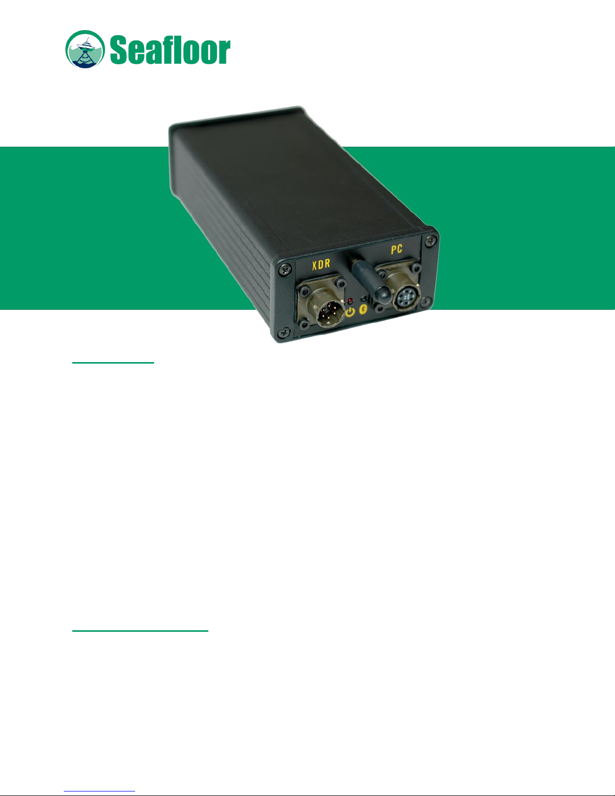
• Sonarmite BT Echosounder
- Internal Battery
- Bluetooth
- IP67 Weatherproofing
- MILSPEC connectors and caps

• 200 kHz Echosounder transducer
- Digital smart transducer
- 7 degree beam
- Bottom tracking technology
- QA Sonar strength signal
- Breakaway design
• 12-volt power supply/charger
- Rapid Charge
- Discharge feature
- Charge disconnect when battery is fully charged
• Serial interface cable
- Used for data transfer
• Training CD-ROM
- User Manual
- Other programs
• 1-year Warranty parts & labor
Options
• HydroLite-TM Pole Kit
• Custom Case
• GPS
• Datalogger
• Software
• Sidescan Sonar
Getting Started
The Sonarmite echosounder can be used in multiple configurations.
• Log in Hypack or other hydrographic survey software on laptops
• Using DGPS
• RTK GPS
• Survey Topo Software on data collectors
• SM Mobile Software
• RC Unmanned Boats
• Robotic Total Stations
Switching the System On
Plug in the Transducer cable to the control box; look for a blinking red LED light. Red
light indicates that the system is on and outputting depths. The transducer MUST be in

water to output depths.
Bluetooth
When red light is blinking the system is powered on, a Bluetooth connection is now
available. You must connect with your collection device of choice (refer to your data
collector manual). When Bluetooth is connection is on, a solid blue LED light will appear.
Serial
A serial cable is included to output data from the Sonarmite. Transducer must be
connected and red LED light blinking to output data.
Data Collection
The Sonarmite has eight output formats, depending on the software used for data
collection. Changing these formats and also sound velocity will be covered in a
separate section below. Please visit our website support section for the specific setup
guides for your system: http://www.seafloorsystems.com/support.html
Bar checking
Bar checking is calibrating the system for the sound velocity of the water you will survey
in. There are only two methods of doing this:
1. A digital bar check (example Odom Digibar Pro).
2. Building a bar check consisting of a flat, large base at a fixed distance from the
transducer. For shallow water use you can use sound velocity tables to set your
Sonarmite close to the desired setting. To do this you would get a water temperature
from mid water column and refer to proper sound velocity table for fresh or salt water.
Please call if you have further questions.
Using the seabed for calibration is not acceptable; this should only be used for rough
check.
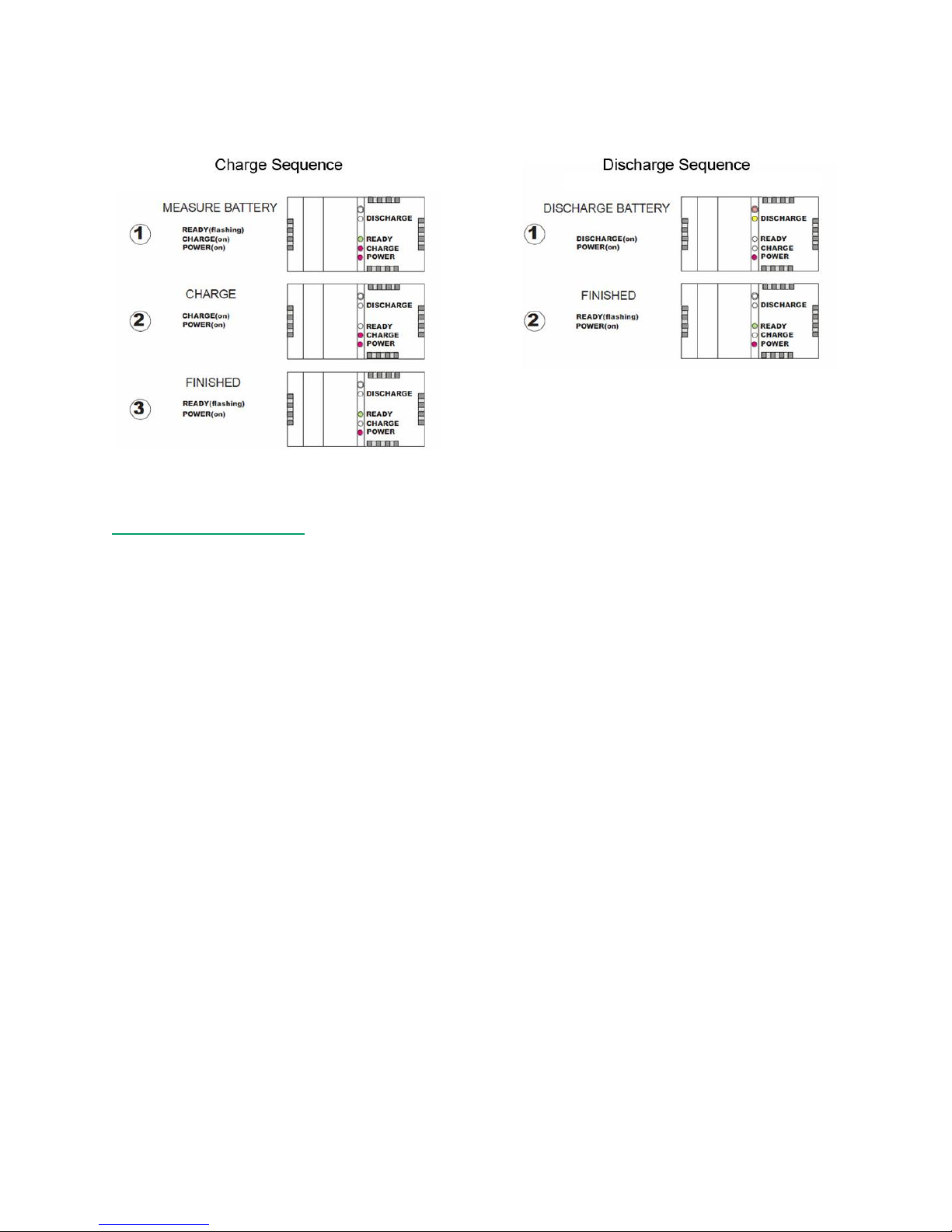
Internal Battery Charging
Charge the battery the night before using, every six months you can do a discharge
and full recharge.
Sonarmite Settings
On the next few pages we will review the several output data formats, how to change
them and changing sound velocity.
1. Put transducer in water. Can be small bucket.
2. Insert transducer connector to Sonarmite control box, look for blinking red light.
3. Connect to terminal program.
a. SENA BTERM via Bluetooth: http://seafloorsystems.com/pdf/sena_bterm.pdf
b. WCOM32 Bluetooth or serial to laptop, software is included on Sonarmite
CD.
4. View streaming data
Control F will cycle through the output formats below.
Control S will save the output format.
Control R will reset the system to default output, MUST be in system format for this
to work.
a. Format Old Sonarmite (example output below)
1 0.48 0 0 0 8.9 115 0
1 0.48 0 0 0 8.9 115 0
1 0.48 0 0 0 17.8 116 0
1 0.48 0 0 0 8.9 115 0
1 0.48 0 0 0 8.9 115 0
Old Sonarmite format is the default format. Trimble, Carlson, SM Mobile
and Hypack all use these formats. The 0.48 is the depth, the 8.9 is the volts

output of the internal battery and the 115 is the sounding return quality
number from 70 to 135.
b. Format ASCII mode (example output below)
0.48
0.48
0.48
0.48
0.48
0.48
0.48
ASCII mode is used mainly by Leica users and 0.48 would be the depth.
c. Format 2 DBT NMEA mode (example output below)
$SMDBT,1.6,f,0.48,M,,*5C
$SMDBT,1.6,f,0.48,M,,*5C
$SMDBT,1.6,f,0.48,M,,*5C
$SMDBT,1.6,f,0.48,M,,*5C
$SMDBT,1.6,f,0.48,M,,*5C
$SMDBT,1.6,f,0.48,M,,*5C
This is a standard NMEA output which can be used with various logging
software.
d. Format 4 Odom SBT mode (example output below)
et 47
et 47
et 47
et 47
et 47
et 47
This is an Odom output; it can be used if you have logging software that
needs an Odom data format.
e. Format 5 Deso 25 mode (example output below)
DA 0.48 m
DA 0.48 m
DA 0.48 m
DA 0.48 m

DA 0.48 m
DA 0.48 m
f. Format 6 Polled mode (example output below)
This will be blank
g. Format 7 mode used for system settings (example output below)
SYS> 54 0.48 109 109 0 116 1500 0.2 0
SYS> 15 0.48 109 109 0 116 1500 8.9 0
SYS> 13 0.48 109 109 0 115 1500 8.9 0
SYS> 14 0.48 109 109 0 116 1500 8.9 0
SYS> 14 0.48 109 109 0 116 1500 8.9 0
SYS> 14 0.48 109 109 0 116 1500 8.9 0
This is the system format; here you change the sound velocity output.
Control U will increase from the default 1500 and Control D will decrease
in increments of 10. When you are satisfied with the sound velocity,
Control S will save. You would then Control F to reach your desired output
format. Control S again and you are done.
h. Format 8 New Sonarmite format (example output below)
1 0.48 8.9 115 0
1 0.48 8.9 115 0
1 0.48 8.9 115 0
1 0.48 8.9 115 0
1 0.48 8.9 115 0
1 0.48 8.9 115 0
1 0.48 8.9 115 0
New Sonarmite is currently for in house testing only.

Using the Sonarmite/HydroLite-TM in the field
The HydroLite-TM Pole Kit makes mounting the Sonarmite Echosounder very easy. The
YouTube setup video will show you how to assemble the HydroLite-TM pole kit. I would
suggest buying the transducer mounting bracket at the very least.
http://www.youtube.com/watch?v=lwIeobCUxJ4
1. After you have assembled the HydroLite system, you will need to find the best
location to mount on your craft. Over the side is usually preferred. Aero ration
from the engine in the rear can disrupt soundings. The transducer should be the
lowest point of the vessel. When measuring the rod height off-set you would start
at the bottom of the transducer.
2. You want the pole as straight as possible; this may change when the operator or
passengers are on the boat. It’s always good policy to note the draft of the
transducer.
3. Usual survey speed is between two and four mph, the slower you go the more
soundings you will log. Surveying in a grid format is the best way to ensure proper
coverage of the survey area.
F.A.Q
Is Dual Frequency required ?
Dual frequency echo sounders were originally designed for use by sea going
vessels to give reliable depths in deep water situations (low frequency) and
more accurate navigation within shallow areas (high frequency). Low frequency
is of little use in shallow hydrographic surveys
•Physical accuracy is outside IHO specifications
•Power consumption prohibits true portable use
•Minimum depth possible outside survey requirements
Can mud thickness can be measured with Dual Frequency ?
The residual difference between low and high frequency shown on an
echogram gives the impression that mud thickness can be measured. In fact the
trace does give an impression of soft sediment, however, in most sounders this is
just the difference in reflected energy as a result of simple penetration of higher
power low frequency signals plotted against the low power high frequency

returns.
To measure mud thickness and avoid litigation on wrong results the surveyor
should use equipment specifically designed for geophysical measurements such
as a sub-bottom profiler, penetrometer, seismograph or a simple bottom sample
grab
Is a Barcheck required ?
Many older technology echo sounders needed to "Warm up" before they
became stable, in addition to their internal frequency/timing circuits varying
with ambient conditions the physical parameters that effect speed of sound in
water also varied with location. The accepted solution was a ''Barcheck'' where
a large plate was lowered in a specified sequence where the depth measured
by the echo sounder to the plate was compared with an absolute stave or tape
measurement. This method ensured that all variable parameters were included
in the calibration, as a gross check the Barcheck was normally also performed
at the start and end of a survey.
There are several problems with this method ....
•The location of the barcheck is only relevant to the water column at that
particular barcheck location and time.
•Older analogue echo sounders gave the user facilities to ''fiddle'' with many
parameters during the survey, modern digital sounders do not expose settings
such as gain and threshold.
•The older instruments do not record changes to instrument settings during the
survey.
•Narrow beam sounders with bottom detection algorithms can misdetect the
moving plate.
•Modern digital electronic timing components are very accurate and stable.
There is still a requirement for calibration of sound velocity but if required this
should be measured using a calibrated Sound Velocity Probe lowered through
the water column to build a Velocity Profile.
A simple equivalent of the Barcheck is to accurately visit several locations within
the survey area which have a known elevation (normally derived from GPS and

a weighted tape) and these points used as a reference throughout the duration
of the survey
Should Pitch/Roll angle be applied to the depth ?
Many surveyors assume that sonar is like a laser being shone through the water
and that the distance measured should be assumed is a hypotenuse
measurement to be trigonometrically corrected by any Pitch/Roll angle that has
been measured.
The best physical analogy of the echo sounder beam would be a torch light
beam that is shone over an area, within that area there is a small piece of mirror
that reflects the light at that point, sonar is very similar except that the reflected
point is normally the closest point within the beam.
What is a narrow beam transducer ?
The properties of a transducer are normally a function of its physical size/shape
and its resonant frequency. The beam pattern of a given transducer is normally
presented as a radial distribution pattern versus output power applied. This
generally means that the spread (beamwidth) of the transmitted ultrasound
increases with amplitude. Most modern echo sounders use a Digital Signal
Processing (DSP) technique to reduce the power/gain of its transmitted signal
and thus maintain the minimum beam width for a given transducer.
The advantage of a narrow beamwidth survey transducer is the ability to "see"
into narrow valley shapes thus gaining a more representative definition of the
bottom surface being surveyed. This is contrary to the navigation use of an echo
sounder which has a reasonably wide beamwidth where the returned signal
within the beam is the ''shoalest'' or shallowest point within the beam, obviously
of more interest for hull clearance requirements.
Is my Fishfinder OK for survey use ?
Modern Fishfinder type navigation echo sounders use quite sophisticated DSP
techniques to show the bottom surface, bottom type and fish in the water
column. As with the beamwidth discussion the electronics of a 'leisure' Fishfinder
are not designed for a survey application. In particular the depth values are

either heavily averaged to show a smooth transition in numeric depth values or
are optimized to show the shallowest depth seen in the particular beam area.
Similarly survey echo sounders make efforts to remove anomalies such as fish
swim bladder reflections from the measured data.
Do I need more pings per second ?
Assuming the pings all return good values the advantage of more pings per
second is that the survey boat can travel faster and therefore cover much larger
areas in a shorter time. The assumption that more pings provide higher quality
dense survey data is not so, density is a function of boat speed and is still
constrained by the limitations of transducer beamwidth as discussed above.
More pings can also create more noise with the high degree of insonaration in
the water and particularly in shallow water situations with multipath reflections.
What is Latency ?
Latency is the time difference between a position and depth being recorded,
the topic is extremely complex and can included some of the following sources
of error ...
•GPS position correction source time differences
•Time of flight of ultrasound in water
•Serial transmission of data to, from and through computer systems
•Physical mounting of antennas and transducers
In general the survey software attempts to minimize the error by recording a
precise timestamp on each piece of data recorded, the sum of all latency
sources can then be calculated by post-process adjustment of the data using a
''Patch Test'' algorithm. The degree of latency is dynamic so is always a function
directly related to speed of the boat when data acquired, faster the boat then
more potential latency
What effects sound velocity
The speed sound travels through water is directly proportional to the density of
the water, the parameters which change the density are ....

• Turbidity - the amount of sediment in suspension within the water.
• Salinity - The amount of substance (normally salt) dissolved in the water.
• Temperature - The temperature of the water sample.
• Pressure - Sum of water depth and barometric pressure.
All of the above parameters can vary considerably in any particular water
column but the assumption made with a single beam echo sounder is ....
• the sound travels near vertically so does not suffer any refraction.
• the sound travels there and back so is the average of all condition changes
This manual suits for next models
1
Table of contents
Other Seafloor Marine Equipment manuals

Seafloor
Seafloor HydroCat 180 User manual

Seafloor
Seafloor AutoNav PLUS User manual

Seafloor
Seafloor HydroLite-DFX User manual

Seafloor
Seafloor AutoNav User manual

Seafloor
Seafloor HyDrone ASV User manual

Seafloor
Seafloor EchoBoat-240 User manual

Seafloor
Seafloor EchoBoat 160 ASV User manual

Seafloor
Seafloor TriDrone Programming manual
Popular Marine Equipment manuals by other brands


Pfannenberg
Pfannenberg PA 130 Operating and installation instruction

Raymarine
Raymarine Quantum 2 installation instructions

GST
GST I-9403 manual

jotron
jotron TR-2600 Operation and installation manual

Lewmar
Lewmar AutoAnchor 150 Installation and operation instructions

Furuno
Furuno FSV-25 MARK-2 installation manual