Bosch Rexroth Marex SB User manual

Version 2.10
15.07.2003
Manual / Marine
Marex SB

Short Instructions
Please do also see the general advice in chapter 1.
Step Description
1Select engine type (chapter 2 "overview")
Assembly
2Adjust SYSCON switch board in accordance with engine type (chapter 2 "overview")
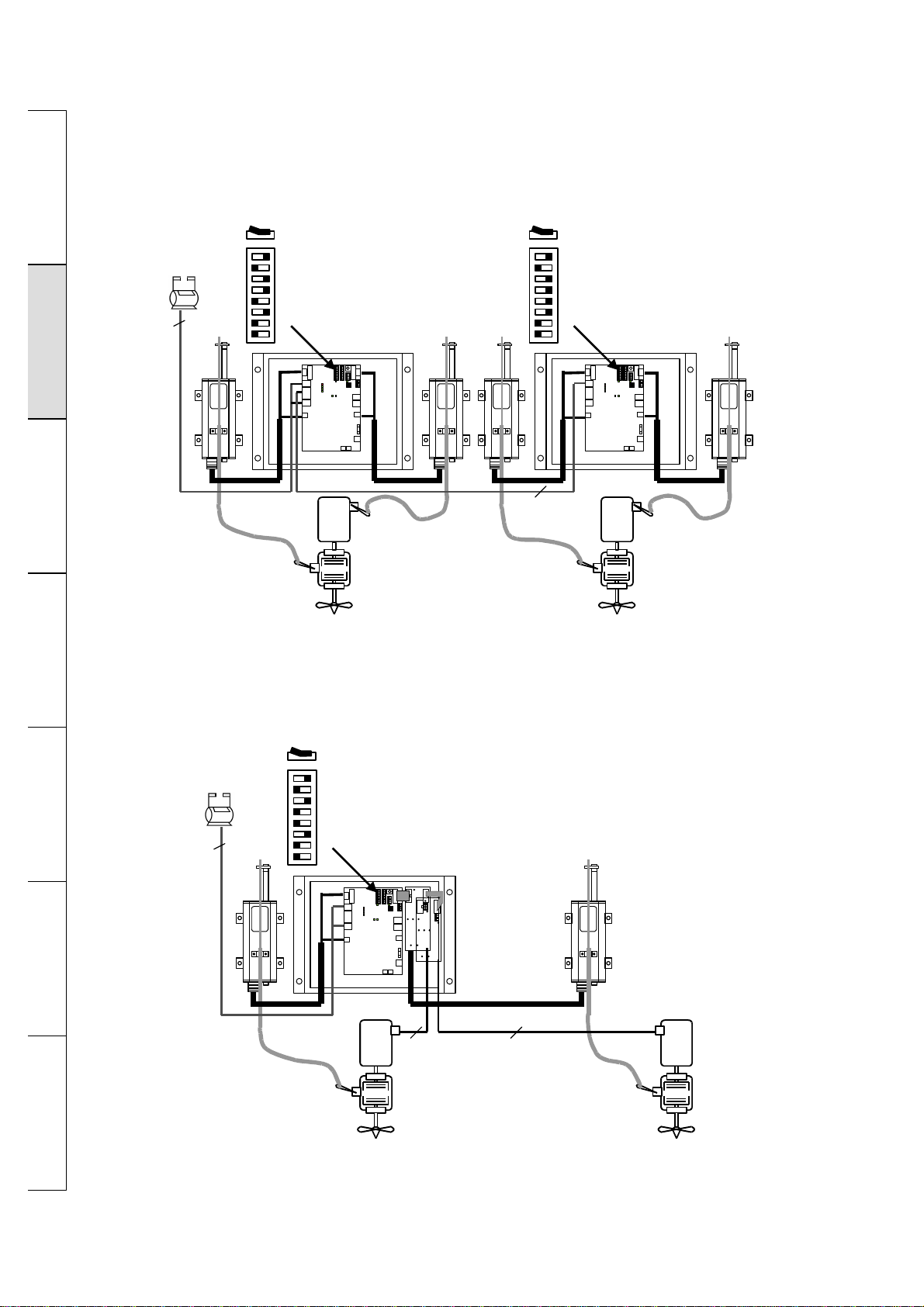
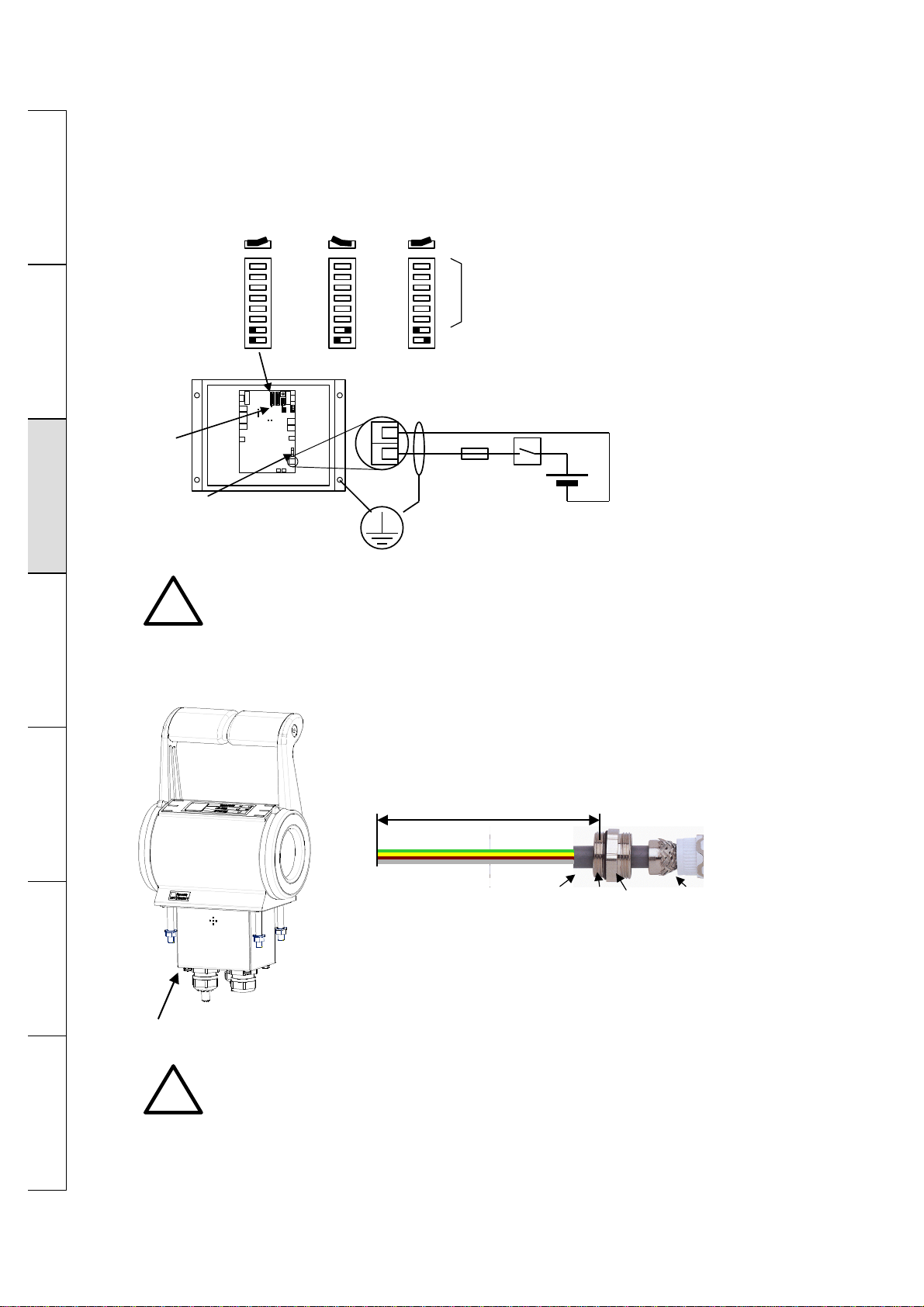
3-Wire components and adjust switches
-Power supply (chapter 3.1)
-Control head (chapter 3.2)
Attention: Enter the control head ID and write it down.
-Throttle and gear control ("mechanical" chapter 3.3, "electrical" chapter 3.4)
-Extra functions if necessary (alarm, engine start interlock, idle speed relay, chapter 3.5
ff.)
Commissioning
4Enter control heads (chapter 4.2)
Enter additional functions of control heads if applicable.
5For mechanical throttle control: enter nominal value for idle speed (chapter 4.3)
6For mechanical gear shifting: adjust position ahead / astern
(chapter 4.4)
7Enter extra functions if necessary (power boost, increased idle speed, see chapter 4.3,
synchronization, buzzer in neutral, change of control station, see chapter 4.2).
Mooring Trial
8Adjustment of delay times for gear shifting (chapter 4.4)
Adjustment of power boost if applicable (chapter 4.3)
Adjustment of increased idle speed if applicable (chapter 4.3)
Sea Trial
9Adjustment of reversing delay times (chapter 4.4)
How to operate the system is described in chapter 5.
In case of malfunction, an error analysis as explained in chapter 6 has to be carried out.
Imprint: The copyright of this user manual remains the property of Bosch Rexroth AG.
Included are instructions and technical drawings which may not be reproduced or
copied either in part or whole, nor may they be used for evaluation or distributed for
competition purposes.
The diagrams and drawings used in this manual are for guidelines only and are not be
used for the actual design.
This edition supersedes all previous ones.
Order No.: 883 890 060 3
Bosch Rexroth AG
Department Marine Technique
Bartweg 13
30453 Hannover
P. O. Box 91 07 62
30427 Hannover
Tel.: +49 (0)5 11-2136-2 51
Fax.: +49 (0)5 11-2136-1 62
e-mail: [email protected]
Internet: http://www.boschrexroth.de

Table of Contents Page
1 General 1.1 System components 1
1.2 General preconditions for the operation 2
1.3 Mounting advice 2
1.4 Operating advice 2
2 Overview 2.1 Single engine 3
2.2 Twin engine 5
3 Wiring 3.1 Voltage supply 7
3.2 Control head 7
3.3 Mechanical throttle control / gear shifting 10
3.4 Electrical throttle control / gear shifting 11
3.5 Alarm relays 15
3.6 Engine start interlock 16
3.7 Idle gas relay 18
4 Adjustment 4.1 Hardware configuration 19
4.2 Control head 20
4.3 Speed 23
4.4 Gearing 25
4.5 Reset to default 28
5 Operation 5.1 General 29
5.2 Activation and request control station 30
5.3 Station transfer 31
5.4 Warming Up 32
5.5 Increased idle speed 32
5.6 Synchronising 32
6 Error analysis 6.1 Error at control station 33
6.2 Error indication control panel 34
Appendix Control unit 40

1
General Overview Wiring Operation Error Analysis Appendix
Adjustment
1 General
1.1 System components
Designation Code No. Photo Symbol
Control head
(single engine) 362 241 100 0
Control head
(twin engine) 362 241 000 0
Control unit 346 068 000 0
DC actuator 323 698 020 0
I/O-extension board 346 068 721 2 1
2
3
4
Synchro-board 346 068 730 2
Push-/Pull-cable 2m 323 699 415 2
Mounting kit 323 699 006 2
Additionally required:
Data cable LIYCY 4 x 1mm²
Supply cable Ölflex 100 2 x 2,5mm²
Throttle cable LIYCY 2 x 0,75mm² for electrical throttle control only
Gearing cable LIYCY 7 x 1mm² for electrical gear shifting only
Cable alarm LIYCY 2 x 0,75mm² if alarm system is connected
Cable start interlock LIYCY 2 x 0,75mm² if engine start interlock is connected
Cable idle gas LIYCY 2 x 0,75mm² if idle gas is connected

2
GeneralOverviewWiringAdjustment
Operation
Error AnalysisAppendix
1.2 General preconditions for the operation
(According to classification rules)
Indication of the current cruising command*
The current cruising command (speed, gearing position) must be indicated on every control station.
Indication of active control station*
It must be indicated on every control station which control station is in command.
If, from any control station, any other station is visible, the indication of current cruising command and
active control station is not necessary (e. g. on small yachts).
Capacity of independent actuation*
Besides the remote control, a second possibility of controlling speed and gearing must be provided.
Emergency stop-button*
A separate emergency stop-button for the engine must be installed on every control station
independent from the remote control.
*These components are not included in the MAREX SB delivery.
1.3 Mounting advice
Cables to be connected to the control unit must always be provided with the metallic cable joints
supplied. The joints are mounted as shown below:
Mounting work must be done only if the system is in voltage-free condition. The power supply must be
secured against activation in this case.
Mounting and commissioning work must be carried out by skilled personnel and in accordance with
the manual only.
1.4 Operating advice
Do not reach into the actuator while it is in operation. You risk injuring.
The remote control MAREX SB has been designed for the control of Diesel engines. If it is applied for
petrol or gas propulsion systems, its components must be installed outside the hazardous area. The
instructions for hazardous areas have to be followed.
shielded cable
sleeving
outside cone Inserted sealing
pressure screw
conductors cable

3
General Overview Wiring Operation Error Analysis Appendix
Adjustment
2 Overview
2.1 Single engine
Single engine – mechanical throttle control and gear shifting
Throttle and gear shifting are operated by mechanical rods.
1
2
3
4
5
6
7
8
1
S1 S2
70 mm
100 N
70 mm
100 N
shielded cable
typeLIYCY
4 x 1 mm
2
SYSCON
Single engine - electrical throttle control, mechanical gear shifting
The throttle is adjusted electrically (4 ... 20 mA), the gears are shifted by mechanical rods.
1
2
3
4
5
6
7
8
1
S1
4...20 mA
70 mm
100 N
shielded cable
typeLIYCY
4 x 1 mm
2
shielded cable
typeLIYCY
2 x 0,75 mm2
SYSCON

4
General
OverviewWiringAdjustmentOperationError AnalysisAppendix
Single engine - mechanical throttle control, electrical gear shifting
Throttle is actuated by mechanical rods, gear shifting is controlled by 24 V-signals.
1
2
3
4
5
6
7
8
1
A2
70 mm
100 N
24 V
shielded cable
typeLIYCY
4 x 1 mm2
shielded cable
typeLIYCY
7 x 1 mm2
SYSCON
Single engine – electrical throttle control and gear shifting
Throttle is adjusted electrically (4 ... 20 mA), the gears are shifted using 24 V-signals.
1
2
3
4
5
6
7
8
1
24 V
4...20 mA
shielded cable
typeLIYCY
4 x 1 mm
2
shielded cable
typeLIYCY
7 x 1 mm2
shielded cable
typeLIYCY
2 x 0,75 mm2
SYSCON

5
General Overview Wiring Operation Error Analysis Appendix
Adjustment
2.2 Twin engine
Twin engine – mechanical throttle control, mechanical gear shifting
Throttle and gear shifting are controlled by mechanical rods.
1
2
3
4
5
6
7
8
1
A1 A2
1
2
3
4
5
6
7
8
1
A1 A2
port starboard
70 mm
100 N
70 mm
100 N 70 mm
100 N
70 mm
100 N
shielded cable
typeLIYCY
2 (4) x 1 mm2
shielded
cable
typeLIYCY
4 x 1 mm2
SYSCON SYSCON
Twin engine – electrical throttle control, mechanical gear shifting
Throttle is actuated electrically (4 ... 20 mA), the gears are shifted by mechanical rods.
1
2
3
4
5
6
7
8
1
A1 A2
70 mm
100 N 70 mm
100 N
4...20 mA 4...20 mA
12
port starboard
I/O-extension board 1:
actuation rpm port
I/O-extension board 2:
actuation rpm starboard
shielded
cable
typeLIYCY
4 x 1 mm2
shielded cable
typeLIYCY
2 x 0,75 mm2
shielded cable
typeLIYCY
2 x 0,75 mm2
SYSCON

6
General
OverviewWiringAdjustmentOperationError AnalysisAppendix
Twin engine – mechanical throttle control, electrical gear shifting
Throttle is adjusted by means of mechanical rods, gear shifting is controlled by 24 V-signals.
1
2
3
4
5
6
7
8
1
A1 A2
12
port starboard
70 mm
100 N
70 mm
100 N
24 V 24 V
I/O-extension board 1:
actuation gearing port
I/O-extension board 2:
actuation gearing starboard
shielded
cable
typeLIYCY
4 x 1 mm2
shielded cable
typeLIYCY
7 x 1 mm2
shielded cable
typeLIYCY
7 x 1 mm2
SYSCON
Twin engine – electrical throttle control, gear shifting electrical
Throttle is adjusted electrically (4 ... 20 mA), gear shifting is operated by 24V-signals.
1
2
3
4
5
6
7
8
1
12
port starboard
24 V 24 V
4...20 mA 4...20 mA
I/O-extension board 1:
actuation gearing port
actuation rpm port
I/O-extension board 2:
actuation gearing starboard
actuation rpm starboard
shielded
cable
typeLIYCY
4 x 1 mm2
shielded cable
typeLIYCY
7 x 1 mm2
shielded cable
typeLIYCY
7 x 1 mm2
shielded cable
typeLIYCY
2 x 0,75 mm2
shielded cable
typeLIYCY
2 x 0,75 mm2
SYSCON

7
General Overview Wiring Operation Error Analysis Appendix
Adjustment
3 Wiring
3.1 Voltage supply
!For systems approved by classification societies, the voltage range 12V or has to
be selected. If the supply voltage exceeds or falls below the range by +30% or -
25% respectively, a corresponding error message will be issued.
3.2 Control head
Advice how to mount the connecting cable
loosen screws and
lift housing cover
100 mm
shielded-
cable
sleeving
male
taper sealing
insert pressure
-
screw
preparation connection cable
!The data cable must be prepared as shown above. The cables must not be
squeezed when assembling the components after the wiring.
The sealing of the housing must be fitted correctly to guarantee protection type
IP65.
1
2
Vcc
GND
12V / 24V DC
10 A nominal current
30 A peak current
(acc. to Lloyds Register)
fuse
16A T +
-
1
2
3
4
5
6
7
8
7
1
2
3
4
5
6
7
8
7
1
2
3
4
5
6
7
8
7
voltage
12...24 V DC voltage
12 V DC voltage
24 V DC
supply line 2,5mm2,
length. 10m max
screened
earthing at one of the 4 mounting screws directly
(connection to ship mass)
fuse
10A T
LED -
readyness
main
switch
switch for configuration
of engine type
(see chapter 2 overview)

8
General
OverviewWiring
Adjustment
OperationError AnalysisAppendix
Entering the identification (ID)
!To enable the control to identify the control heads, an individual ID must be
entered once at every control head (e. g. control head bridge ID 1, control head
port ID 2, control head starboard ID 3)
ID 0 is not admissible.
àThis procedure is not necessary, if the automatic ID setting is used. (Chapter
4.2)
To enter the ID, the housing cover must be removed.
Adjustment
ID (1...6)
starboard side
port side
X1
bottom side control head
adjustment
ID (1...6)
LED
power supply
ok
LED
communication
ok
!
7
6
5
4
3
2
1
On every control head, an individual
ID must be entered
once.
ID 0 is not admissible.

9
General Overview Wiring Operation Error Analysis Appendix
Adjustment
Wiring control head
7
6
5
4
3
2
1
7
6
5
4
3
2
1
7
6
5
4
3
2
1
7
6
5
4
3
2
1
7
6
5
4
3
2
1
7
6
5
4
3
2
1
screened line
(LIYCY)
4 x 1 mm2
total length 60m max.
optional switch: station tranfer interlock
(required for ECR stations according to classification rules)
control head
ID 1 control head
ID 2 control head
ID 3
gr
gb
br
ws
gr
gb
br
ws
gr
gb
br
ws
gr
gb
br
ws
gr
gb
br
ws
bridge
at last
head
!
!
The IDs of the control heads
must be different.
4
3
2
1
2
1
2
1
ws
br
gr
gb
screened line
grounded at both ends
+
-
Terminal Designation Colour
10 V white (ws)
2+8 V brown (br)
3CAN – yellow (gb)
4CAN + green (gr)
5CAN end
6switch -
Terminal assignment control head
7switch +
!At the last control head, a bridge must be connected between terminals 4 and 5.
Special application: twin engine with mechanical throttle control and gear shifting
7
6
5
4
3
2
1
7
6
5
4
3
2
1
7
6
5
4
3
2
1
7
6
5
4
3
2
1
control head
ID 1
control head
ID 2
gr
gb
br
ws
gr
gb
br
ws
gr
gb
br
ws bridge
at last
head
!
!
The IDs of the control heads
must be different.
4
3
2
1
2
1
2
1
ws
br
gr
gb
shielded cable
4 x 1 mm2
earthed at both ends
gr
gb
4
3
2
1
2
1
2
1
gr
gb
port starboard
shielded cable
2 (4) x 1 mm2
earthed at both ends
!remove bridge
terminal 2/3
Example: 2 control head

10
General
OverviewWiring
Adjustment
OperationError AnalysisAppendix
3.3 Mechanical throttle control and gear shifting
actuator 2
2
1
3
2
1
actuator 1
1
2
3
1
2
SYSCON
The setting of switchboard SYSCON (switches 1 – 6) assigns the function (speed or gear control) to
the actuators (see chapter 2 overview).
3.3.1 Push-/pull-cable
The mechanical connection between actuator and lever for throttle adjustment or gear control at the
engine is done by push-/pull-cables.
radial excursion: 8° max. to all sides
**
8,5
76 stroke 110 33 max
10-32 UNF-2A
22,1
for half the stroke
170 3
+
9,46
6,35
9,46
min 5
min 5
3,27
**
!
When laying push-/pull cables as few direction changes as possible should be
made. The efficiency of the cables decreases with every deflection.
Deflection angle 90° usable force = 82% of the force applied
Deflection angle 360° usable force = 55% of the force applied

11
General Overview Wiring Operation Error Analysis Appendix
Adjustment
3.3.2 Mounting of the actuator
3.3.3. Connection at the throttle and gear adjusting lever
To fix the push-/pull-cable at the adjusting lever, a ball joint may be used.
3.4 Electrical throttle control and gear shifting
Electrical throttle control
1
2
3
4
71 72 73 74 75 76 77 78 79 80 81 82
+-
4...20 mA
galvanically separated
(max. 500 Ohm)
ECU, EDC
Engine Control Unit
Engine Digital Control
shielded cable
Typ:LIYCY
2 x 0,75 mm2
earthed at both ends
geerdet
!Mounting work may only be carried out if the actuator
is idle.
Risk of injury!
"s"
hexagone nut
counter bearing
ball joint
!When adjusting the traveling range of the actuator (stroke), it must be ensured
that both markings remain visible in the end positions.
The travel may not be blocked by exterior mechanical stops. Misadjustment may
lead to blocking and distruction of the electric actuators.
stroke 70 mm

12
General
OverviewWiring
Adjustment
OperationError AnalysisAppendix
Electrical gear shifting without feedback
!If inductive loads shall be switched, these must be provided with a free-wheeling diode.
If not, the digital output may be destroyed.
71 72 73 74 75 76 77 78 79 80 81 82
ahead
Vcc, 2A astern
Vcc, 2A
solenoid valve
reversing gearbox
screened cable
type LIYCY
7 x 1 mm2
grounded at both ends
Solenoid valve not included in MAREX SB delivery.
The power supply for the gearbox must be fused separately.
An emergency manual override for gear shifting must be provided.
LED set ahead (73)
LED set astern (75)
1
2
3
4
gear feedback off
1
Indication gear condition
1
2
3
4
1
2
3
4
relay with
free-wheeling diode

13
General Overview Wiring Operation Error Analysis Appendix
Adjustment
Electrical gear shifting with separate feedback
71 72 73 74 75 76 77 78 79 80 81 82
Voraus
Vcc, 2A Zurück
Vcc, 2A
solenoid valve
with free-wheeling diodes
reversing gearbox
screened cable
type LIYCY, 7 x 1 mm2
grounded at both ends
Solenoid valve and pressure switch are not included in the MAREX SB delivery.
The power supply for the gearbox must be fused separately.
An emergency manual override to shift gears must be provided.
LED set ahead (73)
LED set astern (75)
LED act. astern (78)
LED act. astern (76)
1
2
3
4
gear feedback on
sep. feedback on
1
Indication gear condition
1
2
3
4
1
2
3
4
pressure switch
!If inductive loads shall be switched, these must be provided with a free-wheeling diode.
If not, the digital output may be destroyed.
Electrical gear shifting with collective feedback 71 72 73 74 75 76 77 78 79 80 81 82
Voraus
Vcc, 2A Zurück
Vcc, 2A
reversing gearbox
screened cable
type LIYCY, 7 x 1 mm2
grounded at both ends
Solenoid valve and pressure switch are not included in the MAREX SB delivery.
The power supply for the gearbox must be fused separately.
An emergency manual override to shift gears must be provided.
LED set ahead (73)
LED set astern (75)
LED collective-
feedback (76)
1
2
3
4
gear feedback on
sep. feedback off
1
Indication condition gearbox
1
2
3
4
1
2
3
4
solenoid valve
with free-wheeling diodes
pressure switch
!If inductive loads shall be switched, these must be provided with a free-wheeling diode.
If not, the digital output may be destroyed.

14
General
OverviewWiring
Adjustment
OperationError AnalysisAppendix
Power supply for electrical gear shifting
1
2
3
4
fuse
2A T
+
-
71 72
Vcc GND
supply line 2 x 1 mm2,
length max. 10m
The power supply shown above is recommended according to the classification rules.
Alternatively, the control unit may supply the voltage for the electrical gear control:
1
2
3
4
1
2
3
4
71 72
Vcc GNDVcc GND
1 2
!
!When the control unit supplies the voltage for the electrical gear control, the power
supply is not protected by fuse. In this case, the control unit must be protected
separately (see chapter 3.1 "power supply").

15
General Overview Wiring Operation Error Analysis Appendix
Adjustment
Mounting the I/O-extension boards
viewing direction
X101 X102
X101 X102
X31
I/O-extension board I (actuation port )
I/O-extension board II (actuation starboard )
12
1
2
control unit
3.5 Alarm relays
1
2max. 30 V DC
max. 0,5
A
shielded cable
type LIYCY
2 x 0,75 mm2
earthed
at both ends
LED alarm relay
1
2potential-free
relay contact
closed in case
of error
!If inductive loads shall be switched, these must be provided with a free-wheeling diode.
If not, the digital output may be destroyed.

16
General
OverviewWiring
Adjustment
OperationError AnalysisAppendix
3.6 Engine start interlock
supply -
battery +
-
starter-
battery
+
-
engine
single engine
12
twin engine
1
2
3
4
2
configuration
start interlock
port
connection to
I/O-extension board 1
starboard
connection to
I/O-extension board2
+
-
+
-
engine
+
-
+
-
engine
shielded cable
type LIYCY
2 x 0,75 mm2
shielded cable
type LIYCY
2 x 0,75 mm2
The relay "start interlock" is closed whenever the active control head is in neutral or warming up (see
5.4 "warming up") is active.
Wiring control unit
1
2max. 30 V DC
max. 0,5
A
shielded cable
type LIYCY
earthed at both ends
LED start interlock
1
2
potential-free
relay contact
closed ,
when
lever in neutral or
warming up active
engine start interlock via control unit
!If inductive loads shall be switched, these must be provided with a free-wheeling diode.
If not, the digital output may be destroyed.
Wiring I/O-extension board
1
2
3
4
2
configuration
start interlock
potential-free
relay contact
max. 30V DC
max. 2 A
shielded cable
type LIYCY
2 x 0,75 mm2
earthed at both ends
71 72 73 74 75 76 77 78 79 80 81 82
LED start-
interlock
1
2
3
4
closed when,
lever in neutral or
Warming Up active
!If inductive loads shall be switched, these must be provided with a free-wheeling diode.
If not, the digital output may be destroyed.

17
General Overview Wiring Operation Error Analysis Appendix
Adjustment
!Two special cases must be considered when wiring the engine start interlock
Engine start interlock, special application 1:
Twin engine with mechanical throttle control and gear shifting
1
2
3
4
5
6
7
8
1
A1 A2
1
2
3
4
5
6
7
8
1
A1 A2
port starboard
+
-
+
-
engine
+
-
+
-
engine
port starboard
shielded cable
type LIYCY
2 x 0,75 mm2
shielded cable
type LIYCY
2 x 0,75 mm2
Engine start interlock, special application 2:
Using the function "idle gas relay" on twin engines
1
2
1
2
3
4
2
configuration
idle gas relay
-
port starboard
+
-
+
-
engine
+
-
+
-
engine
supply -
battery
Starter-
battery Starter-
battery
+
!Engine start interlock will be released if both levers of the control heads (port and
starboard) are in neutral position or warming up is active.
Table of contents
Other Bosch Marine Equipment manuals

Bosch
Bosch MAGIC.SENS MSS 400 Installation guide

Bosch
Bosch FNM-420-A-RD User manual

Bosch
Bosch FNM-420V-A-WH User manual

Bosch
Bosch FNM-420-A-BS-RD User manual

Bosch
Bosch FNM-420U-A-RD User manual

Bosch
Bosch FNM-420U-A-BSWH User manual

Bosch
Bosch MSS 300 WH-EC Quick start guide

Bosch
Bosch FNM-320-SRD User manual

Bosch
Bosch FNM-420V-A-WH User manual

Bosch
Bosch FNM-420U-A-WH User manual
Popular Marine Equipment manuals by other brands

NORSELIGHT
NORSELIGHT XENON R50 Series user manual

KVH Industries
KVH Industries TracNet H90 installation guide

Raymarine
Raymarine P70 Installation and operation instructions

Raymarine
Raymarine ST7000 Operation manual

Raymarine
Raymarine ST60 Tridata Owner's handbook

Simrad
Simrad NSS9 evo3S Operator's manual