SEA Saturn 600 Quick start guide

Italiano
English
Français
Español
Sistemi Elettronici
di Apertura Porte e Cancelli
International registered trademark n. 804888
®
cod. 67410324
MOTORIDUTTORI PER CANCELLI SCORREVOLI
MOTOR REDUCERS FOR SLIDING GATES
MOTEURS POUR PORTAILS COULISSANTS
MOTOREDUCTORES PARA CANCELAS CORREDIZAS
BOXER
1000 - 2000
2000 Threephase
REV 07 - 12/2015
SATURN
600 - 1000 - 2000 (230V-115V)
1500 24V (230V-115V)
1200 24V FAST
500 SUPER FAST 24V (230V)

MOUNTING AND CONNECTING INSTRUCTIONS
1Adjustable foundation plate
2Anchor bolts
3Pinion protection
4Adjusting screws cover
5Pinion
6Reducer release lever
TECHNICAL DATA
Power supply
Power
Absorbed current
Motor capacitor
Working frequency
Working Temperature
Thermoprotection
Weight
Anticrushing clutch
Protection degree
Pinion Z16 (Z20) speed
Maximum torque
Gate maximum weight
Gate maximum length
Mechanical clutch
Limit switch
7 Screw for mechanical clutch adjustment
(Where present)
8Electronic unit
9Magnetic encoder (Where present)
MAIN PARTS DENOMINATION
ENGLISH
Only the OIL version has a clutch
Sistemi Elettronici
di Apertura Porte e Cancelli
International registered trademark n. 804888
®
SATURN - BOXER
230 V 50/60 Hz
330W 550W 750W
1,6 A 2,6 A 3,0 A
10 F 12,5 F 12,5 F
35% 35% 30%
-20°C +55°C
150°C
12 kg 13 kg 14,5 kg
Electronic Electronic/Mechanical
Ip55
0,15 (0,18) m/s
30 Nm 55 Nm 70 Nm
600 kg 1000 kg 2000 kg
6 m 10 m
No Yes Yes
Inductive or mechanical
~
mmm
600 1000 2000
SATURN 600-1000-2000 (230V) 1000 2000
550W 750W 400W
2,6 A 3,0 A 1,0 A
10 µf 12,5 µf -
55%
-20°C +55°C
150°C -
14 kg 15 kg
Electronic/Mechanical Mechanical
IP55
0,15 (0,18) m/s
55 Nm 70 Nm
1000 kg 2000 kg
10 m
Yes
Inductive or mechanical
2000 THREEPHASE
230V (±5%) 50/60Hz
230V/380V(±5%) 50/60Hz
BOXER 1000-2000-2000 Threephase
600 1000 2000
SATURN 600-1000-2000 (115V)
115 V (±5%) 50/60 Hz
400W 500W
3,2 A 5,0 A
50 µf 70µf
20% 25% 40%
-20°C +55°C
150°C
12 kg 13 kg 14,5 kg
Electronic Electr./Mech.
IP55
0,15 (0,18)m/s
50 Nm 55Nm 70Nm
600 kg 1000kg 2000kg
6 m 10 m
No Yes
Inductive or mechanical
TECHNICAL DATA
Power supply
Power
Absorbed current
Motor capacitor
Working frequency
Working Temperature
Thermoprotection
Weight
Anticrushing clutch
Protection degree
Pinion Z16 (Z20) speed
Maximum torque
Gate maximum weight
Gate maximum length
Mechanical clutch
Limit switch
TECHNICAL DATA
Power supply
Power
Absorbed current
Motor capacitor
Working frequency
Working Temperature
Thermoprotection
Weight
Anticrushing clutch
Protection degree
Pinion Z16 (Z20) speed
Maximum torque
Gate maximum weight
Gate maximum length
Mechanical clutch
Limit switch
Note: The frequency of use is valid only for the first hour at 20°C
room temperature.
Example: Saturn.
The SATURN and the BOXER are motor reducers designed for
the automation of sliding gates with grease lubrication or in oil
bath, depending on the versions.
The irreversibility of the motor reducers allows a perfect and safe
gate closing, and makes the installation of an elecric lock
unneccessary. In case of electric power cut, the lock device
placed on the front part of the motor reducer allows the manual
opening and closing. The operators are equipped with an
electronic clutch device and adjustable mechanical clutch (if
present), which provides an adjustment of the thrust on the
gate, furthermore the electronic inversion system (optional)
through encoder makes out of the Saturn and Boxer motor
reducers a safe and reliable operators allowing in a simple way
to respect the laws in force in the country where the product will
be installed.
cod. 67410324
9
7
5
3
1
2
4
6
8
9
Power supply
Motor
Absorbed power
Working frequency
Working Temperature
Weight
Anticrushing
clutch
Protection degree
Pinion speed
Maximum torque
Gate max. weight
Gate maximum
length
Limit switch
REV 07 - 12/2015
1500 24V
(230V)
230V~ 50/60 Hz
24V
100W
60%
14,3 kg
Electronic
IP55
0 - 60 Nm
1200 kg
10 m
Inductive/mechanical
-20°C +55°C
1500 24V
(115V)
SATURN 500 SUPER FAST 24V - 1200 FAST 24V (230V) - 1500 24V (230V)-(115V)
1200 FAST 24V
(230V)
500 SUPER FAST
24V (230V)
115V~ 50/60 Hz
0,40 m/s Max
(Z20)
0 - 65 Nm0 - 45 Nm
1500 kg500 kg
TECHNICAL DATA
0,32 m/s Max
(Z16)
0,25 m/s Max
(Z13)

SATURN FAST 1200 24V (230V)
Saturn 500 S.Fast (24V)
SATURN 500 Super Fast (24V)
SATURN 600 (230V)
SATURN 600 (230V)
SATURN 1000 (230V)
SATURN 1000 (115V)
SATURN 2000 (115V)
SATURN 1500 24V (230V) (115V)
SATURN 600 (115V)
SATURN 600 (115V)
SATURN 1000 (230V)
SATURN 1000 (115V)
SATURN 2000 (230V) SATURN 2000 (230V)
SATURN 2000 (115V)
1. GATE ARRANGEMENT
Before starting with the installation check if all the gate parts
(fixed and mobile) have a strong and as less as possible
deformable structure, also make sure that :
a) The leaf is rigid and compact;
b) The inferior slideway is perfectly straight, horizontal and
without any obstacles which could obstruct the gate sliding;
c) The inferior sliding wheels are equipped with greasable or
water tightened bearings;
d) The superior slideway has been produced and placed so that
the gate is in a perfect vertical position;
e) Mechanical stops of the leaf are always installed in order to
avoid possible derailment of it.
DIMENSIONS (mm)
320
345
12 5
Fig. 2
Z16
Z20
108 mm
116 mm
MINIMUN DIMENSION Q
2.2.
2.3. Before concreting in the plate, make sure that it is perfelcty
leveled and that the distance of 58-67 mm as shown in Fig. 2 is
respected.
Before cementing the plate insert a flexible plastic duct of at
least 30mm in diameter into the special hole of the plate.
2. FOUNDATION PLATE ANCHORAGE
To install the foundation plate it is necessary to:
2.1. Prepare a concret basement with the dimensions shown in
Fig. 1 where the foundation plate and the anchor bolts will be
concreted.
NOTE: It is recommended, gate structure permitting, to lift the
foundation plate about 50mm from the ground, in order to avoid
eventual water stagnation.
43-58
150
04 2
250
Plinto
Fig. 1
65
58-67
3. CABLES PASSAGE ARRANGEMENT
Saturn and Boxer are provided with two different holes for
electric cables passage.
It’s very important to make the low - tension 230V~ cables pass
through one hole and and the very low safety tension cables
24V through the other one (Fig. 3)
DIMENSIONS (mm)
Sistemi Elettronici
di Apertura Porte e Cancelli
International registered trademark n. 804888
®
cod. 67410324
ENGLISH
10 REV 07 - 12/2015
2000 kg
1200 kg
1000 kg
600 kg
20%
40%
25%
35%
55%
60%
30%
BOXER 1000
BOXER 2000 - 2000 Trifase
BOXER 1000
BOXER 2000 - 2000 Trifase
500 kg
1500 kg
SATURN - BOXER MOTOR REDUCERS USING GRAPHIC
Use frequency
Gate maximum weight
Motor reducers

Fig. 3
4. FITTING OF THE MOTOR REDUCER
4.1. Insert the 4 grains into the special holes, so that it is possible to
adjust the motor reducer height on the plate (Fig. 4).
At the end of installation check if the 4 crub screws are well
gripped on the foundation plate.
4.2. Fix the motor reducer to the foundation plate with the 2 included
nuts, adjusting the side position (Fig. 5) so to respect the shown quota
in (Fig. 2).
4.3. Remove the closing loading oil cap (red) and substitute it with
that supplied apart provided with the airhole (black).
Hole 1
Hole 2
Fig. 4
Fig. 5
5. GEAR RACK MOUNTING
5.1. Release the motor and open the leaf completely;
5.2. Fix on each gear rack element the support pawls with the
appropriate lock screws, make sure to put them in the upper part
of the hole (Fig. 6) ;
5.3. Lean the gear rack element on the toothed pinion of the
motor in parallel to the ground slideway of the gate, as shown in
Fig. 7 and electrically weld the central pawl B to the gate
structure (Fig. 8).
Manually move the gate until pawl C is placed corresponding to
the pinion and fix it through electric welding. Repeat the same
procedure for pawlA after having placed it corresponding to the
pinion;
5.4. Make sure that all the gear rack elements are perfectly
aligned and placed correctly (teeth in phase). It’s suggested to
place two aligned elements in front of a third one as shown in
Fig.9;
5.5. Repeat the above described operation for all the remaining
gear rack elements which have to be installed;
5.6. To avoid that the door weights down on the pinion (Fig.10)
lift up the whole rack about 1,5 mm.
Warning: Keep a gap of about 0,5 mm between pinion tooth
and gear rack tooth;
5.7. Make sure that the gear rack works at the center of the
pinion along all rack elements, if necessary, adjust the length of
the spacers.
Fig. 7
ABC
Fig. 6
Fig. 8
Sistemi Elettronici
di Apertura Porte e Cancelli
International registered trademark n. 804888
®
cod. 67410324
ENGLISH
11
REV 07 - 12/2015

Fig. 9
6. LIMIT SWITCHADJUSTMENT
6.1. In order to install and adjust the limit switch in opening, follow
the below mentioned instructions (Fig. 11):
- Take the gate to complete opening,
- Place the small plate on the gear rack so that the limit switch is
(small lever in case of mechanical limit switch (Fig. 12); small
pointers placed on the upper part in case of inductive limit switch
(Fig. 13)) in corrispondence of pointX which is placed 50 mm
from the folded side of the small plate (Fig. 14) and fix it with the
delivered screws (Fig. 15 - Fig.16).
6.2. In order to install and adjust the limit switch in closing, follow
the below mentioned instructions (Fig. 11):
- Take the gate to complete closing
- Place the small plate on the gear rack so that the limit switch is
in corrispondence of pointX which is placed 50 mm from the
folded side of the small plate (Fig. 14) and fix it with the delivered
screws (Fig. 15 - Fig.16).
Limit switch in closing
Limit switch in opening
1,5 mm
Fig. 10
Fig. 11
Fig. 12
Mechanical limit switch
Adjusting the trimmer for braking, placed on the electronic
control unit, it is possible to make the gate stop on the desired
position.
Fig. 15
50 mm
X
Fig. 14
Position in which must be the
spring (mechanical limit switch) or
the pointer (inductive limit switch)
Fig. 13
Inductive limit switch
Sistemi Elettronici
di Apertura Porte e Cancelli
International registered trademark n. 804888
®
cod. 67410324
Fig. 16
ENGLISH
12 REV 07 - 12/2015

MAX 10 mm
Sistemi Elettronici
di Apertura Porte e Cancelli
International registered trademark n. 804888
®
7. MAGNETIC LIMIT SWITCH
Fig.17
Fig.18
Fig.19
Fig.20
Fig. 23
AA
8. (Fig. 21 - Fig. 22)GROUNDING
Fig. 22
F
N
Fig. 21
Example: Boxer
Example: Saturn 24V
9. CLUTCHADJUSTMENT (Where present)
9.1. Switch off electric power.
9.2. In order to adjust the clutch it is necessary to:
-Act on the scrub screw “A” (Fig. 23) as follows:
- Turning clockwise = less clutch sensibility / more thrust force
-Counter clockwise = more clutch sensibility / less thrust force
Ex. Boxer
+ power
- sensibility
- power
+ sensibility
Steel rack
Plastic rack
Sliding gate
Magnet
Limit sheet
Rack
Pinion
ENGLISH
13
cod. 67410324 REV 07 - 12/2015

Sistemi Elettronici
di Apertura Porte e Cancelli
International registered trademark n. 804888
®
Fig. 25
2x ,5
1
2x1,5
x
31,5
1x,
15
21,5
x
3x1,5
13x, 5
6x1,5
18 x , 5
1
2
3
4
10
5
67
8
9
Fig. 24
Fig. 26
10. SCREW COVER MOUNTING
At the end of the mechanical installation and after having
executed all the required adjustments, mount the two screw
covers on the operator as shown in Fig. 24.
11. ELECTRIC CONNECTIONS OF THE
INSTALLATION (Fig. 25)
2
The cable mesures are indicated in mm
1) Saturn - Boxer
2) Photocell Sx
3) Photocell Dx
4) Mechanical safety edge
5) Key push botton
6) Flasher
7) Receiver
8) Warning notice
9) Junction box
10) Differential 16A - 30mA
Ex. 230V version with integrated electronic control unit
12. RISK EXAMINATION
The points pointed by arrows in Fig. 26 are potentially
dangerous. The installer must take a thorough risk examination
to prevent crushing, conveying, cutting, grappling, trapping so
as to guarantee a safe installation for people, things and animals
(
)
Re. Laws in force in the country where the installation has been
made.
13. NOTICE
SEAcan not be deemed responsible for any damage or accident
caused by product breaking, being damages or accidents due to
a failure to comply with the instructions herein. The guarantee
will be void and the manufacturer responsibility (according to
Machine Law) will be nullified if SEA original spare parts are not
being used.
This is a quotation from the GENERAL
DIRECTIONS that the installer must read carefully before
installing. Packaging materials such as plastic bags, foam
polystyrene, nails etc must be kept out of children’s reach as
dangers may arise.
The electrical installation shall be carried out by a professional
technician who will release documentation as requested by the
laws in force.
14.
15.
SAFETY PRECAUTIONS:
All electrical work and the choice of the operating logic should
conform to current regulations. A 16 A 0,030 A differential
switch must be incorporated into the source of the operators
main electrical supply and the entire system properly earth
bonded. Always run mains carrying cables in separate ducts to
low voltage control cables to prevent mains interference.
SPARE PARTS:
To obtain spare parts contact:
SEAS.p.A. -Zona Ind.le, 64020 S.ATTO Teramo Italia
ENGLISH
14 cod. 67410324 REV 07 - 12/2015

Sistemi Elettronici
di Apertura Porte e Cancelli
International registered trademark n. 804888
®
Oe
pn
Close
Fig. 27
Fig. 28
16. SAFETY AND ENVIRONMENTAL
COMPATIBILITY:
Don’t waste product packing materials and/or circuits.
When being transported this product must be properly
packaged and handled with care.
SEA reserves the right to do changes or variations that may be
necessary to its products with no obligation to notice.
17. PERIODIC MAINTENANCE
All the above described operations must be done exclusively by
an authorized installer.
Check the oil level (where present)
(Use the oil level rod)
Change oil
Check the release functionality
Check the clutch functionality
(where present)
Check the distance between pinion and gear
rack (1.5 mm)
Check the usury status of pinion and
gear rack
Check the fixing screws
Check the connection cables integrity
Check limit switch functionality and status in
opening and closing and the related
small plates
Annual
4 years
Annual
Annual
Annual
Annual
Annual
Annual
Annual
18. RELEASE SYSTEM FOR SATURN AND
BOXER
18.1. In order to release do as follows:
-Open the lock cover, insert the key and rotate it 90° clockwise
(Fig. 27).
- Pull the release lever until it stops, about 90° approximately
(Fig. 28).
Note: when you pull the release lever, the electronic control
unit receives a stop impulse thanks to a micro-switch
placed inside.
18.2. In order to relock do as follows:
- Push the release lever to complete closing.
- Rotate the key counter-clockwise and extract it.
- Close the protective lock cover.
Once the lock has been restored the electronic control unit
reactivates
Page for both instaler and user
ENGLISH
15
cod. 67410324 REV 07 - 12/2015

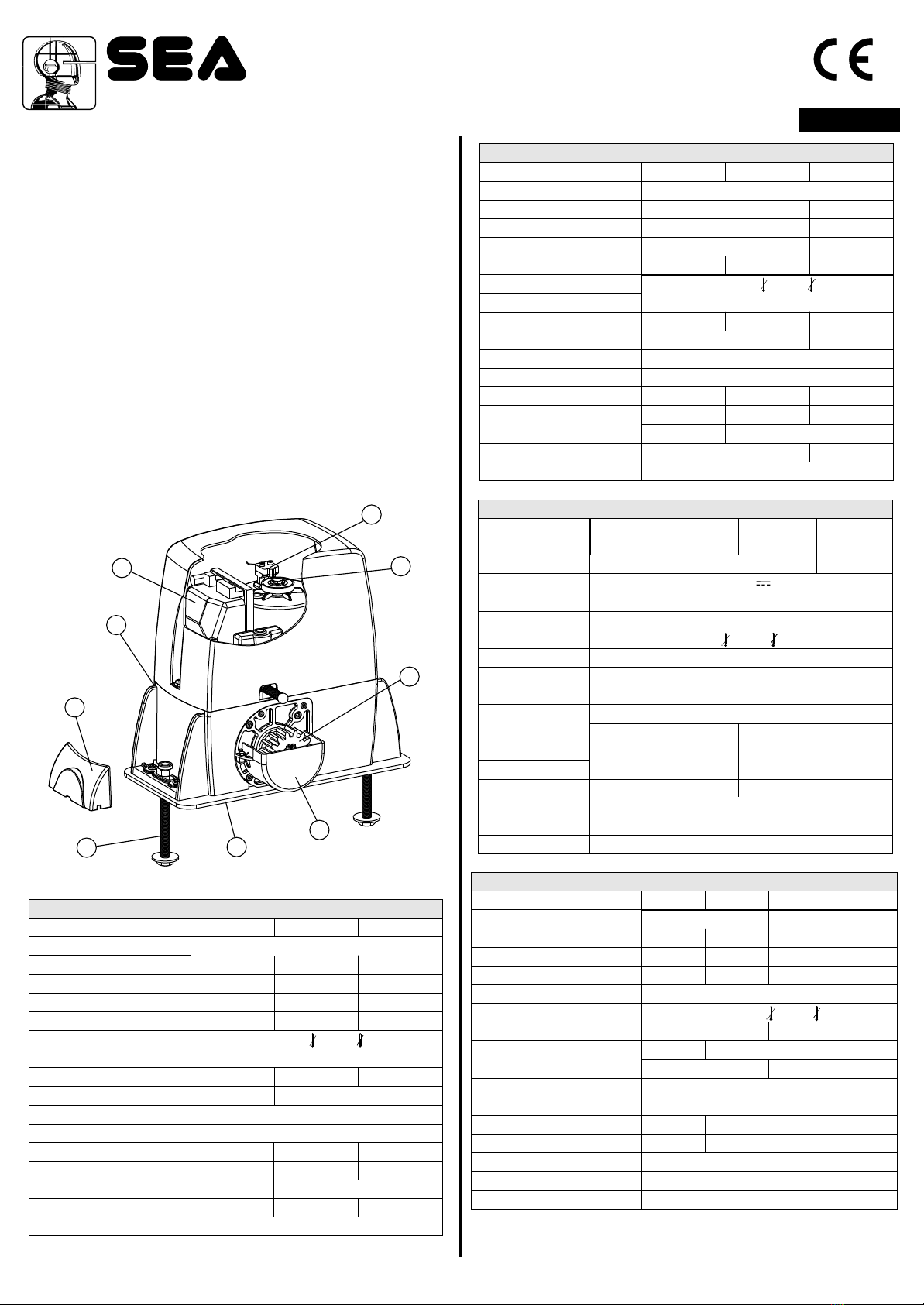
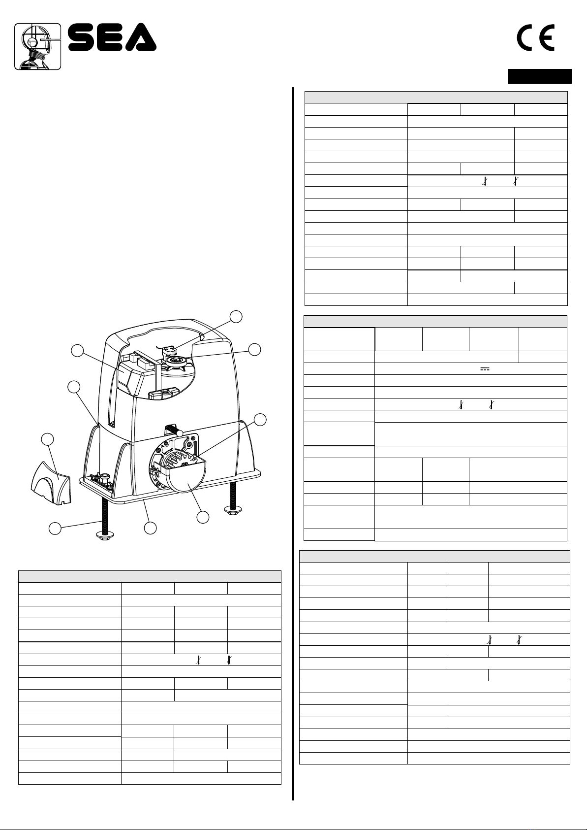
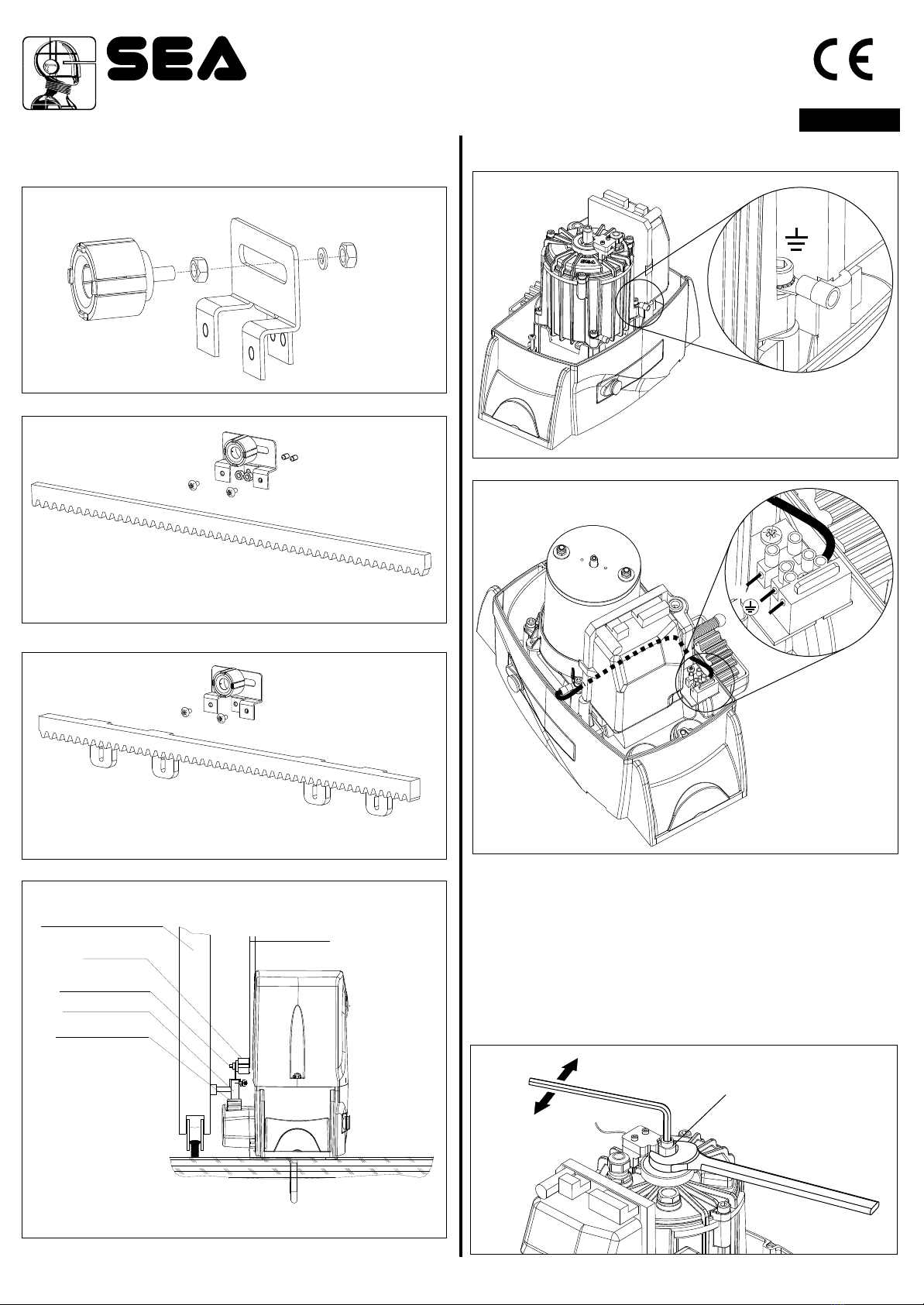
INSTRUCTIONS DE MONTAGE ET CONNEXION
1Plaque de fondation réglable
2Boulons d’ancrage
3Protection pignon
4Couvercle vis de réglage
5Pignon
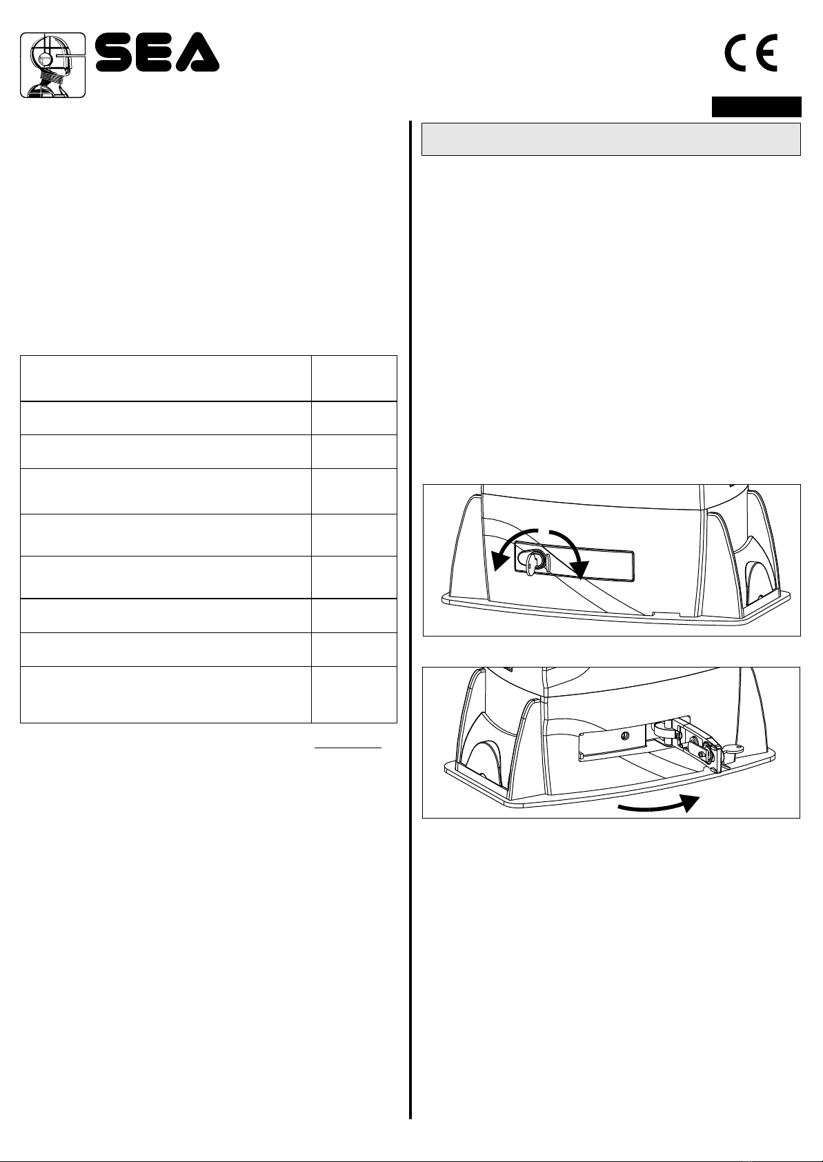
6Levier déverrouillage réducteur
7 Vis réglage friction mécanique
(Où présent)
8Armoire électronique
9Encoder magnétique (Où présent)
NOMENCLATURE COMPOSANTS PRINCIPAUX
Sistemi Elettronici
di Apertura Porte e Cancelli
International registered trademark n. 804888
®
SATURN - BOXER
Exemple: Saturn.
230 V 50/60 Hz
330W 550W 750W
1,6 A 2,6 A 3,0 A
10 F 12,5 F 12,5 F
35% 35% 30%
-20°C +55°C
150°C
12 kg 13 kg 14,5 kg
Electronique Electronique/Mécanique
IP55
0,15 (0,18) m/s
30 Nm 55 Nm 70 Nm
600 kg 1000 kg 2000 kg
6 m 10 m
No Oui Oui
Inductif ou Mécanique
~
mmm
600 1000 2000
SATURN 600-1000-2000 (230V)
DONNEES TECNIQUES
Alimentation
Puissance
Courant absorbé
Condensateur de décollage
Fréquence d’utilisation
Temperature ambiante
Intervention de Thermoprotection
Poids
Friction anti - écrasement
Dégré de protection
Vitesse pignon Z16 (Z20)
Couple max
Poids Max. du portail
Longueur Max. du portail
Friction Mécanique
Fin de course
La friction est présente seulement sur la version OIL
1000 2000
550W 750W 400W
2,6 A 3,0 A 1,0 A
10 µf 12,5 µf -
55%
-20°C +55°C
150°C -
14 kg 15 kg
Electronique/Mécanique Mécanique
IP55
0,15 (0,18) m/s
55 Nm 70 Nm
1000 kg 2000 kg
10 m
Oui
Inductif ou Mécanique
2000 TRIPHASÉ
230V (±5%) 50/60Hz
230V/380V(±5%) 50/60Hz
BOXER 1000-2000-2000 Triphasé
600 1000 2000
SATURN 600-1000-2000 (115V)
115 V (±5%) 50/60 Hz
400W 500W
3,2 A 5,0 A
50 µf 70µf
20% 25% 40%
-20°C +55°C
150°C
12 kg 13kg 14,5kg
Electronique Electr./Méc.
IP55
0,15 (0,18)m/s
50 Nm 55Nm 70Nm
600 kg 1000kg 2000kg
6 m 10 m
No Oui
Inductif ou Mécanique
DONNEES TECNIQUES
Alimentation
Puissance
Courant absorbé
Condensateur de décollage
Fréquence d’utilisation
Temperature ambiante
Intervention de Thermoprotection
Poids
Friction anti - écrasement
Dégré de protection
Vitesse pignon Z16 (Z20)
Couple max
Poids Max. du portail
Longueur Max. du portail
Friction Mécanique
Fin de course
Remarque: La fréquence d'utilisation est valide seulement
pour la première heure à temperature ambiante (20°C).
16
Le SATURN et le BOXER sont des moteurs conçus pour
l’automatisation de portails coulissants avec lubrification des
engrenages à la graisse ou en bain d’huile selon la version
utilisée.
L’irréversibilité des moteurs permet une fermeture parfaite et
sure du portail, évitant l’installation d’une serrure électrique et en
cas de coupure de courant le dispositif de déverrouillage situé
sur la partie frontale du moteur permet l’ouverture et la fermeture
manuelles. Les opérateurs sont équipés d'un dispostif
d’embrayage électronique et d’un embrayage mécanique
réglable (si présent), qui prévoit l’ajustement de la poussée sur
le portail. En outre le dispositif électronique d’inversion
(optionnel), réalisé à l’aide de l’encodeur, fait de Saturn et
Boxer des opérateurs sûrs et fiables permettant de façon
simple le respect des lois en vigueur dans les pays où ce produit
est installé.
cod. 67410324
FRANÇAIS
9
7
5
3
1
2
4
6
8
Electronique
Inductif/Mécanique
DONNEES
TECNIQUES
Alimentation
Fréquence d’utilisat.
Temperature amb.
Poids
Friction anti -
écrasement
Dégré de protection
Vitesse pignon
Couple max
Poids Max. du portail
Longueur Max.
du portail
Fin de course
Moteur
Puissance absorbée
REV 07 - 12/2015
1500 24V
(230V)
230V~ 50/60 Hz
24V
100W
60%
14,3 kg
Ip55
0 - 60 Nm
1200 kg
10 m
-20°C +55°C
1500 24V
(115V)
SATURN 500 SUPER FAST 24V - 1200 FAST 24V (230V) - 1500 24V (230V)-(115V)
1200 FAST 24V
(230V)
500 SUPER FAST
24V (230V)
115V~ 50/60 Hz
0,40 m/s Max
(Z20)
0 - 65 Nm0 - 45 Nm
1500 kg500 kg
0,32 m/s Max
(Z16)
0,25 m/s Max
(Z13)
Other manuals for Saturn 600
2
This manual suits for next models
8
Table of contents
Other SEA Door Opening System manuals
Popular Door Opening System manuals by other brands

RIB
RIB TAG Reader manual

CAMDEN
CAMDEN CM-300 installation instructions

Ebelco
Ebelco DHI224L-110 Installation instruction

RYTEC
RYTEC Spiral HZ installation manual

Automatic Technology
Automatic Technology GDO-6 EasyRoller installation manual

Assa Abloy
Assa Abloy SARGENT 2900 FIREGUARD installation instructions

Command access
Command access SLP-UL-M-KIT installation instructions

Dormakaba
Dormakaba 8900 FT installation instructions

CNC Solutions
CNC Solutions DOOR MATE manual

Dictator
Dictator DICTAMAT 900-21 Technical manual

SOMFY
SOMFY Yslo Flex 2 RTS installation guide

Cal-Royal
Cal-Royal N-F98CVR installation instructions