Dorex DX2 PV User manual

WD-OD002(682)
DX2PV-FV-INST 2021-11
DX2 PV/FV Installation Instructions
Grade 1, Surface vertical rod device (Panic or Fire Exit Hardware)
Installation Sequence
1. Carefully read and understand the installation instructions, templates and door
preparation BEFORE starting any installation or door preparation.
2. Prepare door for the installation of the exit device and any applicable trim.
3. Follow exit device and trim installation steps using supplied components and
mounting hardware.
4. Test function and performance after installing each component.
5. Perform a function and performance test at completion of installation.

COMPONENTS OVERVIEW
2 / 12
Cover
Cover Screws
Center
Case
Screws
Center Case
Top Strike
Top Latch
Top Rod
Rod Guide
Bottom Latch
Latch Cover
Sleeve
Side Screws
Rod Guide Screws
Bottom Strike
Latch Cover Screws
Latch
Screws
Strike Screws
Sex Bolts
End Cap Bracket Screws
End Cap
End Cap Screws End Cap Bracket
Cover Plate Mechanism Case
Spade Drill5/8"
(For Wood Door)
Tap
Drill Bits
SPECIAL TOOLS REQUIRED
#25,1/8",1/4",
5/16",13/32",#7
Bottom Rod
Push Bar
Side Screws
#8-32,#10-24,1/4-20

SCREW CHART
3 / 12
End Cap Bracket Screws
Center Case Screws
Rod Guide Screws
No.1/4-20 x 1-11/16"
2 x PCS
H
APPLICATION SEX BOLTS
METAL WOOD
No.10-24 x 25/32"
2 x PCS
DA
E
No.10-24 x 11/16"
2 x PCS
F
No.1/4-20 x 1-1/8"
1 x PCS
No.10-12 x 1-11/32"
2 x PCS
I
Cover Screws
No.8-32 x 5/32"
2 PCS
End Cap Screws
No.8-32 x 7/32"
4 PCS
No.8-32 x 5/8"
2 PCS
J
F
No.10-12 x 1-11/32"
3 x PCS
B
No.1/4-20 x 1-1/8"
1 PCS
No.10-24 x 11/16"
3 x PCS
No.10-24 x 11/16"
7 PCS
No.10-12 x 1-11/32"
7 PCS
L
No.1/4-20 x 5/8"
1 PCS No.1/4-20 x 5/8"
1 PCS
E
N O
BE
Trim mount or sex bolts
F
No.10-24 x 11/16"
2 PCS
Center Case Screws
No.10-12 x 1-11/32"
2 PCS
E A
No.10-24 x 1-11/32"
2 PCS
C
G
No.10-24 x 1-11/16"
2 PCS
C
A
No.10-12 x 1-11/32"
2 PCS
No.10-24 x 1-11/32"
2 PCS
No.1/4-20 x 1-11/16"
2 x PCS
H
F
No.1/4-20 x 1-1/8"
2 x PCS
No.1/4-20 x 1-1/8"
2 x PCS
Optional Strike Screws
Top / Bottom Latch Screws
DXAS108 Screws
DXAS227 Screws
Connecting Rod Screws
Default top strike
for DX2FV
106 / 215 Screws
DXAS
DXAS106
Default strike
for DX2PV
DXAS215
Optional
strike for
DX2PV
Default
bottom
strike
DXAS224 DXAS225
DXAS203

4 / 12
DOOR PREPARATION CHART
SEE TRIM INSTALLATION INSTRUCTIONS, TEMPLATES, OR
DOOR PREPARATION DOCUMENTS FOR DETAILS.
C
L
C
L
X
X
METAL
ROD GUIDES
#25 DRILL
#10-24 TAP
TOP STRIKE
#25 DRILL
#10-24 TAP
METAL
METAL
LATCHES
METAL
#25 DRILL
#10-24 TAP
SURFACE MOUNT
WOOD
¹/8" DRILL
PILOT 1" DEEP DRILL THRU
1/4" DRILL
(DEVICE SIDE)
DRILL
(TRIM SIDE)
METAL
WOOD
SEX BOLTS
INSIDE
OUTSIDE
RHR LHR
RHR shown(LHR opposite)
¹/4" Radi us
CUT-OUT
DEVICE SIDE ONLY ⁵/8" DEEP FOR
WOOD DOOR
#7 DRILL
#1/4"-20 TAP
#25 DRILL
#10-24 TAP
METAL
SURFACE MOUNT
N/A
¹³/32"
¹³/32"
USE SUPPLIED MOUNTING
HARDWARE OR APPROPRIATE
FLOOR ANCHORS FOR THE
APPROPRIATE BOTTOM STRIKE
END CAP BRACKET 2-HOLES
CENTER CASE 2-HOLES
CENTER CASE 2-HOLES
BOTTOM STRIKE
DOOR CUT-OUTS
USE APPROPRIATE
TEMPLATE FOR THE
SUPPLIED STRIKE
PREPARE HOLES FOR THE END CAP BRACKET
MOUNTING HOLES AFTER THE EXIT DEVICE
CENTER CASE INSTALLATION AND AFTER
LEVELING THE EXIT DEVICE.
Level
5/16” DRILL
ON DEVICE SIDE
13/32” DRILL
ON TRIM SIDE
13/32” DRILL
THRU
1/8” DRILL
PILOT HOLE 1” DEEP
1/8” DRILL
PILOT HOLE 1” DEEP
WOOD
WOOD
WOOD
WOOD
5/16" DRILL ON DEVICE SIDE
13/32" DRILL ON EXTERIOR SIDE
(FOR THRU BOLTS)
1/2" DRILL THRU HOLE
(FOR TRIM POSTS)
1/8” DRILL
PILOT HOLE , 1” DEEP
13/32" DRILL THRU
(FOR THRU BOLTS)
1/2" DRILL THRU HOLE
(FOR TRIM POSTS)
Fire Exit Hardware
is to be installed on
Fire Doors bearing
the marking “Fire
Door to be equipped
with Fire Exit
Hardware” Any
retrofit or other field
modification to a Fire
Rated opening can
potentially impact the
Fire Rating of the
opening.
IMPORTANT:
• Use supplied templates for field installations.
• Use door preparation documents for door/frame manufacturing.
• Door must be properly reinforced where the exit device chassis and latches
are mounted. The surface must be flush and flat within 1/16" (1.5 mm).
• Prepare the interior of the door using the exit device template or door
preparation and instructions.
• Prepare the exterior of door using the trim template or door preparation and
installation instructions.
• All threaded holes require a minimum material thickness
of 0.125" (3 mm).
• We recommend samples be used to verify preparation before mass door or
frame manufacturing.
• NOT RESPONSIBLE for any physical or property damage due to incorrect /
improper preparation or installation.
FOR DOOR PREPARATION
REFERENCE ONLY.
Verify that this is the latest version of
this document. We recommend
samples be used to verify preparation
before door / frame manufacturing.
SURFACE
MOUNT
FOR THRU BOLTS
OR TRIM
METAL METAL
WOOD

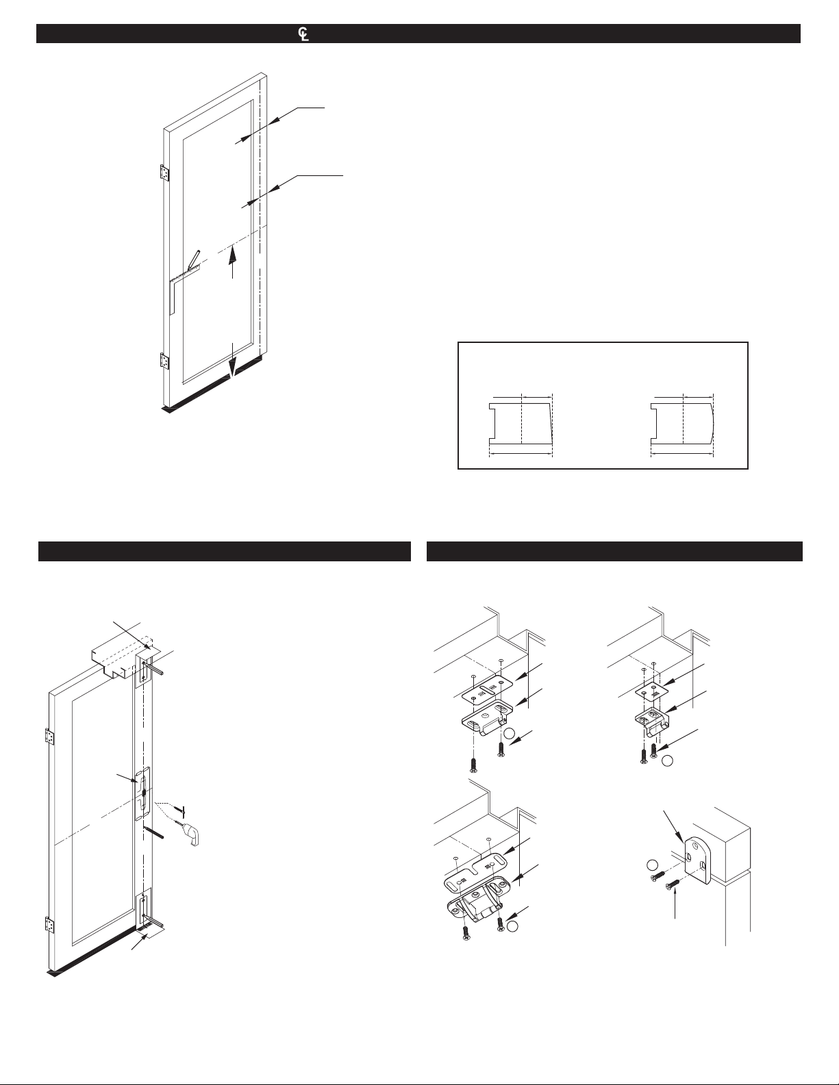
01. DRAW HORIZONTAL CENTERLINE ( )
5 / 12
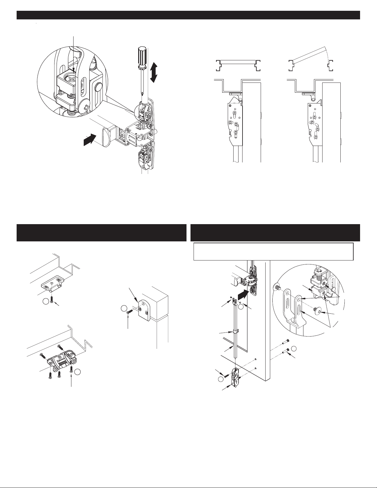
02. LOCATE TEMPLATES AND PREPARE DOOR 03. INSTALL TOP STRIKE AND SHIM
Mark horizontal centerline on inside face of door 39 ⁵/8"
from finished floor as shown. (Continue horizontal center
line to outside face of door if trim is used)
Hinge
Side
C
L
39 ⁵/8"
to Finished
Floor or
Threshold
RHR shown
(LHR opposite)
C
L
Stile
width
Backset
Backset
Min. stile
Beveled edge door Rounded edge door
Min. stile
Backset
E
Install a screw through each slot.
Shim
Strike Screws
Strike Screws
Shim
Strike Screws
E
E
Shim
Strike Screws
E
DXAS106 DXAS203
Default for DX2PV
DXAS215
DXAS108
Default for DX2FV
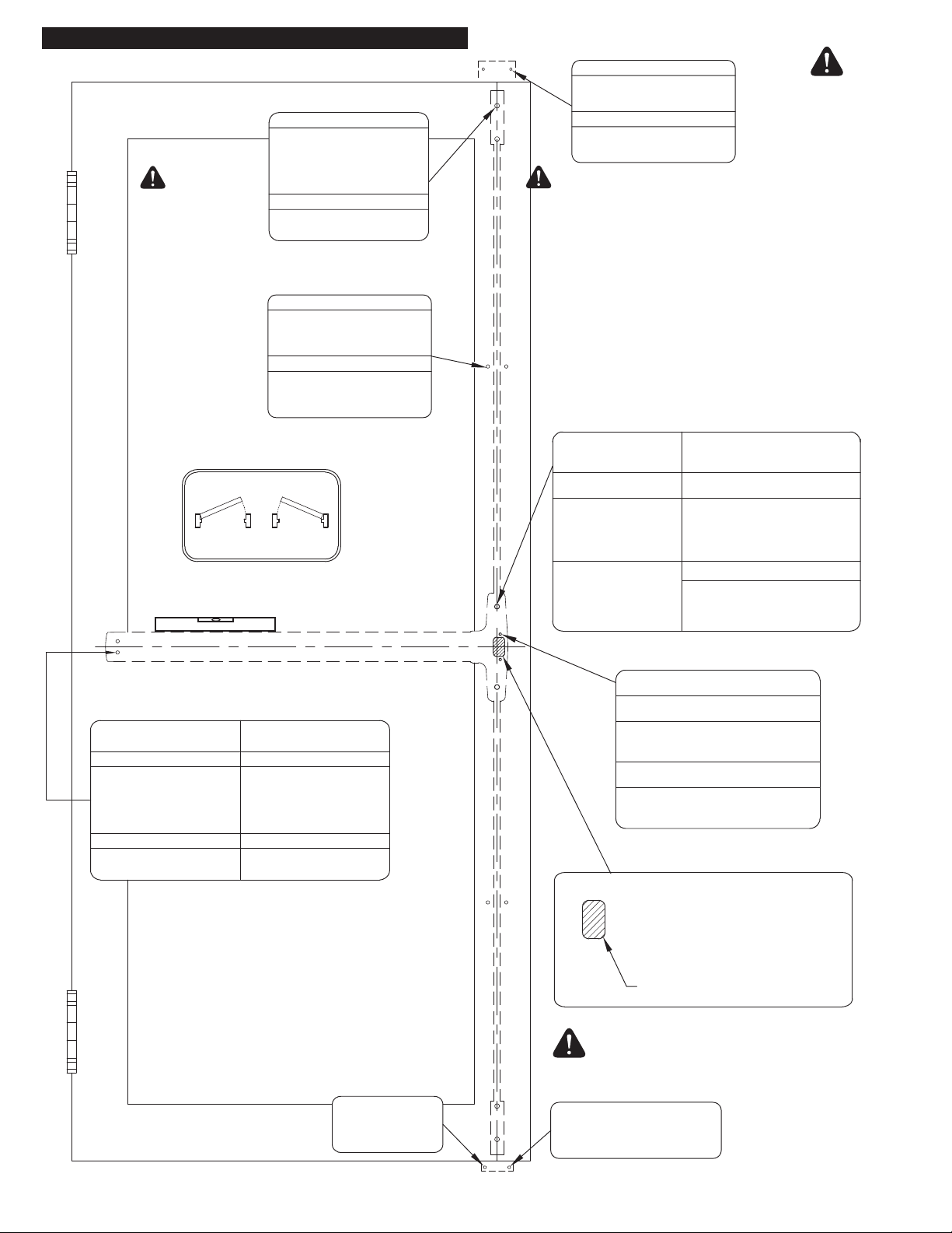
The BACKSET and STILE widths are directly related to:
1. Door Construction: door material, single door, double doors with or
without mullion.
2. Frame Construction: frame material, type and size of door stop on
frame.
3. Top strike length.
Before preparing the door for the exit device center case (chassis), study the
position of the top and bottom latches and the top and bottom strikes.
Refer to the supplied templates or consult with your sales representative for
additional data for door/frames configurations that it are not shown in the
installation instructions.
Backset measurement and Aluminum Door Stile
The backset is measured from the edge of the door as shown below.
The required minimum stile is 2-1/8" with (additional) 1/2" glass stop.
Aluminum doors with a 2-1/8" stile width cannot have a door stop on the
door lock side edge.
1. CAUTION: Prior to using supplied
templates, verify that the templates are
printed to full scale, by measuring some of
the indicated dimensions.
2. Position the center case template in line
with the marked horizontal and vertical
centerlines as shown. Tape the template on
the door and mark the cut-out and mounting
holes centers on the door’s interior side.
3. If trim is used, prepare the door exterior
side using the template and installation
instructions for that trim.
4. With door closed, fold the appropriate top
latch and strike template on the door stop
and inside door surface as shown, ensuring
the vertical centerline aligns with the exit
device vertical centerline. Tape template on
the door and frame, then mark the mounting
hole centers.
5. Fold the appropriate bottom latch and strike
template on the door bottom surface and
floor as shown, ensuring the vertical
centerline aligns with the exit device vertical
centerline. Tape template on the door and
floor and mark the mounting hole centers.
6. Drill and tap required holes and cut the
required cut-outs as indicated on page 4 of
the door preparation document.
7. Attach appropriate strikes as per step 3.
C
L
C
L
C
L
Top Latch
and Strike
Template
Bottom Latch
and Strike
Template
Center
Case
Template
* A ¹⁄4" gap is required
between the bottom of
the door and the finished
floor or threshold.

0
4. CENTER CASE INSTALLATION
06. CUT DEVICE (IF REQUIRED)
05. INSTALL BOTTOM LATCH
6 / 12
Round Bottom Latch
E
DXAS226DXAS225
1. Verify if exit device rail length needs be shortened.
If yes, refer to step 6. The exit device requires a
minimum clearance of 1-3/16” between the frame’s
door stop and the rail end (with end cover
removed). Otherwise install the exit device on door
as required with a trim or without a trim.
2. If exit device is used with a trim, attach the exit
device and the appropriate trim using instructions
and hardware supplied with the trim and the exit
device.
3. If no trim is used and the exit device is surface
mounted on the door, used supplied mounting
hardware as indicated on pages 2, 3, and 4.
4. Fire exit devices must be installed with
through-bolts when installed without a trim.
If a 5/8" diameter hole
is required for the
electrified exit device,
the hole must be
positioned as shown
E
F
1-3/16"
Center Case
Screws
Optional
Trim
7/16"
1. Following the marking of the bottom strike in step 2, prepare the floor
for the appropriate strike and mounting screws
2. If strike is installed on a threshold, provide the required holes and
attach strike with supplied screws.
3. Bottom strike can be installed after bottom latch installation to ensure a
proper alignment.
Pullman Latch
(Defaut)
E
O
N
DXAS227
(Default)
DXAS224
End Cap
1. With anti-rattle clip removed, tape and mark area being cut.
Remove
Anti-Rattle Clip
Tape
Cut off line
Cover Plate
(Flush to Push bar)
Hinge
Side
Center case aligned
with mounting holes.
NOTE:
Device rail cut must be square, smooth and clean for proper fit
with end cap
2. Cut off device and deburr.
Recommended minimum clearance between
door frame stop and device end (with cap
removed) is 1³⁄16"
Face of door stop
DOOR
1³⁄16"
Minimum

07. INSTALL MOUNTING BRACKET AND END CAP 08. INSTALL TOP LATCH AND ROD
08. INSTALL TOP LATCH AND ROD (CONTINUED)
7 / 12
Top Latch
Latch
Screws
Sex Bolts
End Cap
Screws
End Cap
End Cap Bracket
Level Device
End Cap
Bracket Screws
Amount
to
Cut Off
C
J
F
H
Figure 1
Figure 2
Cover Plate
Anti-Rattle Clip
2" Minimum
Top
Latch
Figure 3
Rod
Connecting
Screws
Rod
Connecting
Screw
Notch
Tab
F
Connecting
Bar
Second
Holes
Side
Screws
1. Remove cover plate, insert end cap bracket into the push
bar rail assembly as shown.
2. Level exit device, then mark both mounting hole centers.
Drill and tap, then fasten bracket with the appropriate
mounting screws.
3. Insert cover plate, then slide anti-rattle clip into
position (minimum 2" from end) before fixing end
cap with supplied screws.
1. Align top latch with top strike then install
top latch with two mounting screws (and
through-bolts for Fire). Adjust strike for
proper engagement. (Figure 1.)
2. Supplied rods are for 7 ft (84") door
height. if door height is less than 7 ft,
shorten the top rod by the difference
(Figure 2). Refer to page 10.
3. Attach the connecting Bar to the bottom of the top
rod with supplied screw (Figure 3)
Connecting
Bar
Connecting
Bar
NOTE:
Match notch of the connect-
ing link with tab of rod before
tighten connecting screw
4. Assemble rod guide with rod, thread rod into top latch until first
hole in connecting bar align with first hole in retractor and
fasten with side screws.
Rod
Guide
First Holes
Actual
Door
Opening
Height

09. CHECK TOP LATCH FOR HOLDBACK AND DEADLOCK
8 / 12
10. INSTALL BOTTOM LATCH AND ROD
09. CHECK TOP LATCH FOR HOLDBACK AND
DEADLOCK (SECURE TOP STRIKE)
Close Open
Adjustment Screw
Side
Screws
Rod
Sleeve
Latch Screws
Bottom Latch
Sex Bolts
Connecting Bar
F
First Holes
L
H
Retractor
Side
Screws
Second
Holes
Strike Screws
3rd Strike Screw
Strike Screw
E
E
E
1. Pushing on push bar will retract the latchbolt and
allow the door to open. Latchbolt will stay
retracted, if not adjust the screw on top of the
retractor with a screw driver.
2. Once the door is closed, the strike will engage with the deadlock, which
will allow the latchbolt to extend and engage behind the strike. The
latchbolt cannot be retracted when the door is closed and the deadlock
depressed. If not, adjust the strike position to engage with the device
deadlock.
DXAS215
DXAS106
DXAS108
Once the latchbolt is adjusted properly and engages
with the strike when the door is closed and retracts
when the door is opened; install any additional
screw(s) required to firmly secure the strike used.
1. Install bottom latch with two screws (or with through-bolts for fire
model).
2. Pass bottom rod through rod guide and attach connecting bar to top
of rod
3. Thread the bottom of the rod into the stud of the bottom latch until
the first holes in the end of the connecting bar align with the first
holes in the retractor and fasten with side screws
4. Ensure the bottom strike is properly aligned to engage with the
bottom latchbolt.
FOR LESS BOTTOM ROD MODELS (LBR) OMIT THIS STEP
AND INSTALL AUXILIARY LATCH BOLT.

11. SECURE TWO (2) SIDE SCREWS
9 / 12
12. ADJUST BOTTOM ROD WITH DOOR OPEN
(TOP LATCH RETRACTED)
13. INSTALL ROD GUIDES AND COVERS
WITH SCREWS
Connecting Bar
Tighten Four(4)
Side Screws
Second
Side
Screws
L
Close Open I
D
I
Cover
Cover
Screws
Rod Guide
Latch Cover
Rod Guide Screws
Latch Cover Screws
Install rod guide
at mid point
between latches
and center case.
Fasten two additional side screws through the second holes
in the connecting bar and in the retractor for both the bottom
and top connecting bars.
1. Depress exit device push bar and ensure that the bottom
latch is retracted and stays retracted after the door is
opened. Adjust the retractor screw if needed.
2. Close the door and ensure that the bottom latch engages
in the bottom strike. Adjust strike on the floor or threshold
to ensure proper latchbolt/strike engagement.
3. Open and close door few times and verify that both
latches are engaged and the latch bolt is deadlocked.
4. Secure side screws firmly when final adjustments are
completed.
1. Position rod guides midway between the latches and the
centercase, centered on rods. Mark mounting holes, then
drill pilot hole or drill and tap for fasteners. Secure rod
guides with screws.
2. Install covers on the center case and latches and secure
with screws.

INSTALL FIRE BOLT
10 / 12
SHORTEN TOP ROD / EXTEND TOP ROD
CUT TOP ROD
EXTEND TOP ROD
For 7'
High door
For 8'
High door
For 10'
High door
36 ¹⁄8"
(916 mm)
48 ¹⁄8"
(1221 mm)
23 ²⁷/32"
(605 mm)
48 ¹⁄8"
(1221 mm)
Cut off from flat
end of rod
Step 1: Rod must be shortened if door height is less than 84". Make sure
that the rod is shortened (cut-off) on the flat end of the rod.
Step 2: Tap #1/4-20; 1" deep.
If door height is more than 84", the top rod can be extended (special order)
using an rod extension adaptor, two spring washers and a second rod with
threaded holes at both ends.
4"-6"
3 ³/4" minimum
NOTE: Fire rated exit device with Less Bottom Rod (LBR) application must use a FIRE BOLT
NOTES:
1. Prepare door edge as indicated for the Fire Bolt. Position Fire Bolt 4" to 6" above the finished floor
2. Drill 1" hole in the door edge as indicated and drill and tap for #8-32 machine screws
3. Install Fire Bolt on edge of door and fasten with supplied screws
4. Mark the plug hole on the frame in line with the fire bolt. Drill 1" diameter hole x 1³⁄4" deep on frame or
inactive door edge at same height as the Fire bolt and install strike hole plug
#8-32 TAP
Auxiliary Fire Bolt
DXAFL
Strike
Hole
Plug
1.01"
(25.6 mm)
1" (25.4 mm) Hole
x 3³⁄8" (85 mm) Deep
1/16"
(1.6 mm)
Thick
1.78"
(45 mm)
Recess required if gap between door
and frame is less than 1/8" (3 mm).
Example:
Amount to cut-off = 84" - (Actual Door Height)
Amount
to
Cut Off
Actual
Door
Opening
Height
TOP ROD
AVAILABLE
LENGTHS
84"
(2133 mm)
USING DEFAULT
VERTICAL RODS
FOR 7FT DOOR*
(*) If exit device is installed at location as shown on p.5
Adaptor
Spring/Lock Washer
Extension Rod
Top Rod

11 / 12
DOGGING (PANIC EXIT DEVICES ONLY)
DOGGING ACTIVATION
Cylinder Key
Flat Tool/ or Hex Key
Cylinder
Lock Nut
BOTTOM VIEW
CYLINDER DOGGING INSTALLATION
Hinge
Side
Cylinder
Cylinder
Locating
whasher
Cam
Cover Plate
If cylinder is not installed, remove cover plate and install
cylinder with cam orientation as shown below.
Depress push bar and turn flat/hex key or
cylinder key one full turn for dogging check.
For Alarm (AL) or Latch Monitoring (LM) panel installations,
follow the instructions supplied with those porducts.
Install cylinder to the cover plate with
the cam facing towards the hinges.
Slide cover in
to position on
the rail.

WD-OD002 (682)
DX2PV-FV-INST 2021-11
12 / 12
This manual suits for next models
1
Table of contents
Other Dorex Door Opening System manuals

Dorex
Dorex 1901 User manual

Dorex
Dorex DX2 PC User manual

Dorex
Dorex 441C Series User manual

Dorex
Dorex 1901 Series User manual

Dorex
Dorex 1701 User manual

Dorex
Dorex 8500 Series User manual

Dorex
Dorex DX2 PW User manual

Dorex
Dorex 8500 Series User manual

Dorex
Dorex DX1 PV/FV User manual

Dorex
Dorex 1900 Series User manual