INSTALLATION
MANUAL
Product:Document#:Rev:Page:
MODEL26000GYRO9018324of23
Section1:MECHANICALINSTALLATION
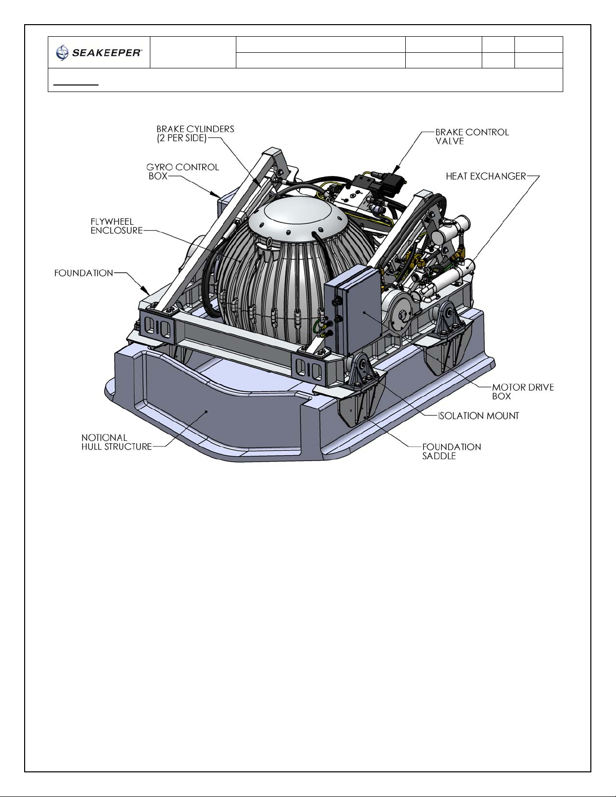
SafetyEnclosure
Thereisalargetorqueaboutthegimbalaxiswhenthegyroisprecessing.Therefore,thegyromustbe
housedinanenclosureoracompartmentorinstalledinacagesopersonnelorgearcannotcomeinto
contactwiththegyrowhileitisprecessing.
Thegyroshouldbetreatedwiththesamerespectonegivesahighspeedrotatingpropellershaftor
engineshaft.Thegyromustbeinstalledsocontactisnotpossiblewhiletheflywheelisspinning.
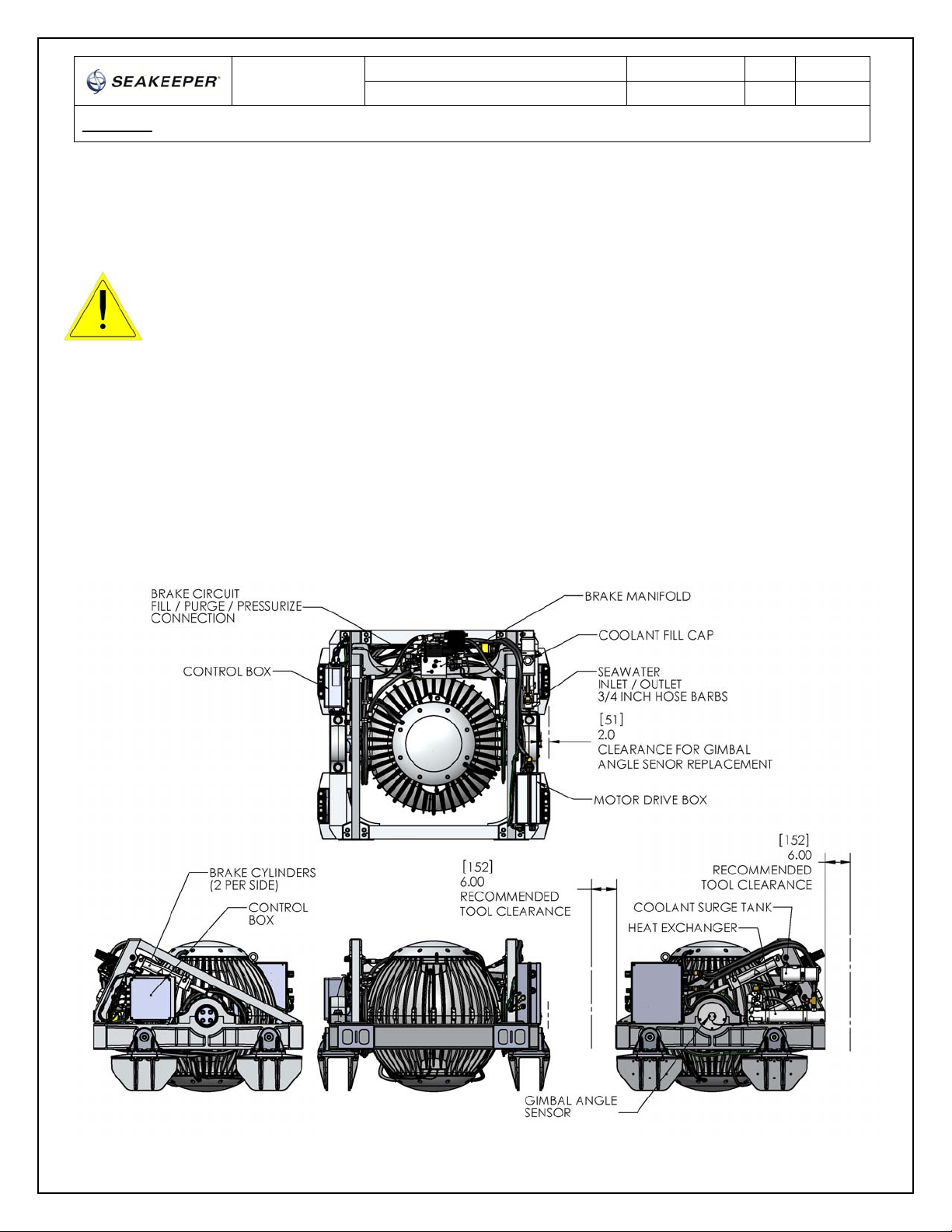
Noise/Soundproofing/Ventilation
Gyronoisehasbeenmeasuredundersteadystateconditions(nowaveload)inSeakeeper'stestfacility.Thesteady
statenoiseistypicallyintherangeof72‐74dBunweighted.Asthefrequenciesemittingthehighestsound
pressuresarelow(likeothermarinemachinery),itisrecommendedthatthegyrobeinstalledinacageina
machineryspacethatisalreadytreatedwithsoundproofing.
Ifthegyrostabilizerhastobelocatedoutsideamachineryspace,itshouldbeinstalledinasounddamping
enclosuretopreventlowfrequencynoise(approximately133Hz)fromenteringthelivingspaces.Inthiscase,the
enclosurecanbeopenatthebottombetweenthehullstringers.Asmallexhaustfanshouldbeinstalledinthetop
oftheenclosuretopullambientairthrutheenclosuresotheairintheenclosuredoesnotheatup.Thiswillensure
thattheownerdoesnotgetnuisanceshutdownsduetotheMotorDriveandBearingtemperaturealarmsinsome
operatingconditions(highambientairtemperature,highseawatertemperature,highseastate,etc).
Thefanshoulddeliver35cuft/min(60cum/hr)whichshouldexchangetheairintheenclosureaboutonceper
minute.Small,massproduced,axialandcentrifugalcoolingfansareavailablewitheitherACorDCinputpower,
ballbearings,extendedtemperaturerange,lownoiseratings,longMTBF,marinized,etc. Locatetheinletatthe
bottomoftheenclosureandmountthefanatthetopasanexhaustfan.Acentrifugalfanmaybebesttominimize
outletarea.Thefanpowerrequirementswouldtypicallybeintherangeof20watts.WhenusingaDCfan,wireit
tothesamebreakerthatprovidespowertotheGyroControlJunctionBoxsothefanturnsonandoffatthesame
timeasthecontroller.