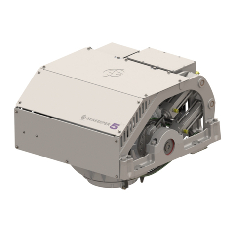
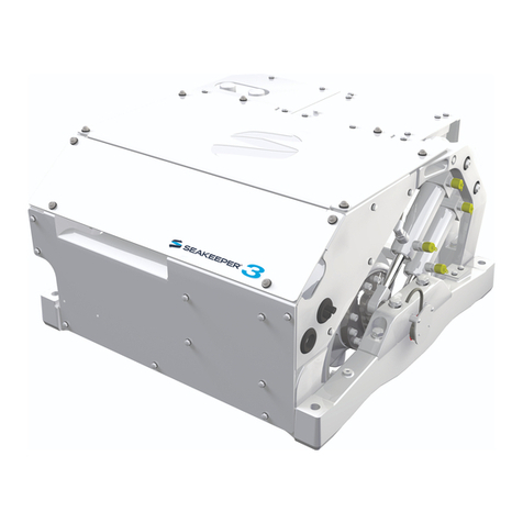
Seakeeper 8000 GYRO User manual

Rev3JULY2013
OPERATIONMANUAL
MODEL8000GYRO

THIS PAGE INTENTIONALLY LEFT BLANK

OPERATION
MANUAL
Product:Document#:Rev:
MODEL8000GYRO901413
MODEL8000GYRO
OPERATIONMANUAL
JULY2013
Contents:
Section1–SystemOverview
Section2–SystemOperation
Section3–PowerFailures,Alarms,andTroubleshooting
Section4–Maintenance
Section5–Warranty,LimitofLiability,PropertyRights
Section6–GyroSpecsandSummary
44425PECANCOURT,SUITE151
CALIFORNIA,MARYLAND,20619,U.S.A
PHONE:410‐326‐1590
FAX:410‐326‐1199
E-MAIL: customerservice@seakeeper.com

THIS PAGE INTENTIONALLY LEFT BLANK

OPERATION
MANUAL
Product:Document#:Rev:Page:
MODEL8000GYRO9014131of11
Section1:SYSTEMOVERVIEW
1.0SystemOverview
TheSeakeeperModel8000Gyrousesgyroscopicprinciplestoreduceboatrollmotionsinwavesand
wakesindependentofboatspeed.OneModel8000Gyrowillreducetherollmotionsofaboatthat
displaces15to25tons.Boatswithhigherdisplacementtypicallyrequiremultiplegyrostoprovidegood
rollreduction.Inmultiplegyroinstallations,thegyrosoperateindependentlyofeachotherand
thereforethismanualonlydiscussesoperationofasingleunit.
AModel8000GyroconsistsofaGyroassembly(includingGyroControlBoxandCompactMotorDrive
Box),serialcommunicationscable,andDisplay.Figure1illustratestheinterconnectionofthese
componentsandtheirinterfacewiththeboat.
FIGURE1–MODEL8000GYROSTABILIZATIONSYSTEMCOMPONENTS
TechnicalspecificationsprovidedinSection6listthepowerconsumption,totalweight,anddimensions
ofthemajorcomponents.Gyroscopicprincipalsthatapplytoboatrollcontrolarediscussedon

OPERATION
MANUAL
Product:Document#:Rev:Page:
MODEL8000GYRO9014132of11
Section1:SYSTEMOVERVIEW
Seakeeper’swebsiteatwww.seakeeper.com.TheSeakeeperwebsitealsocontainsvideosofgyro
operationandvideosofseveraldifferentboatsoperatinginwaveswiththeModel7000Gyroonandoff.
Itisrecommendedthatthereaderplaythesevideospriortoreadingtheremainderofthismanual.
Thegyro’sgimbalangleandthegyro’srateofrotationaboutthegimbalaxis(termedprecessionrate)
playanimportantroleinitsoperation.TheseparametersareillustratedinFigure2.Atzerodegree
gimbalangle,thegyroisvertical;itcanprecessamaximumof+/‐60degreesaboutthisposition.The
amountoftorquethatthegyroexertsonaboat’shulltocounterthewaveinducedrollisdirectly
proportionaltotheprecessionrate.Thefurtherthegyroisfromvertical(zerodegrees)thelowerthe
anti‐rolltorque.TheverticalarrowsinFigure2illustratethedirectionoftheforcesthatthegyroexerts
ontheboat’shulltodamprollmotion.
FIGURE2–GYROPRECESSION

OPERATION
MANUAL
Product:Document#:Rev:Page:
MODEL8000GYRO9014133of11
Section1:SYSTEMOVERVIEW
Seakeepergyroprecessionisactivelycontrolledbyanelectroniccontrollerandahydraulicbrake
throughouteachrollcyclesothegyrosuppliesthemaximumanti‐rolltorqueanddoesnotmake
mechanicalcontactwithhardstopsthatlimitthemaximumgimbalangletravelto+/‐60o.
Thereisalargetorqueaboutthegimbalaxiswhenthegyroisprecessing.
Therefore,thegyroshouldbehousedinacompartmentorinstalledinacageso
personnelcannotcomeintocontactwiththegyrowhileitisprecessing.Ifitisever
necessarytotouchthegyrowhiletheflywheelisspinning,theLockbuttononthe
Keypadmustbedepressedtostopthegyrofromprecessing.Gyromaintenance
shouldnotbeattemptedunlessthegyroislockedandtheflywheelhasstopped
spinning.

OPERATION
MANUAL
Product:Document#:Rev:Page:
MODEL8000GYRO9014134of11
Section1:SYSTEMOVERVIEW
1.1GyroAssembly
Thegyroassemblyconsistsofaflywheelhousedinacastaluminumvacuum‐tightenclosure.The
flywheelspinsaboutaverticalaxisandissupportedbyupperandlowerpairsofbearings.ADC
brushlessmotormountedinsidetheenclosurespinstheflywheelathighspeed.
Theenclosureisfastenedtotwogimbalshaftsthataresupportedbygimbalbearingsoneitherside.
Theseshaftsestablishanathwartshipgimbalaxisaboutwhichtheflywheelandenclosureprecessor
rotateupto+/‐60degreesduringoperation.Eachofthegimbalbearingsissupportedbyasaddlebeam
whichisbondedtothehullstructure.Thesebeamstransfertheloadsthatthegyroproducestothehull
structure.
Anactivehydraulicbrakemechanismislocatedonthegyroassemblytoregulatethegyro’sprecession
motionsaboutthegimbalshaft.Itincludestwohydrauliccylindersmountedonthebrakesaddlebeam
andahydraulicmanifoldonthenon‐brakesaddlebeam.
Acoolantpump,heatexchangerwithreservoir,andthermostaticmixingvalvearelocatedonthebrake
saddlebeamnearthehydrauliccylinders.Bracesforwardandaftoftheenclosureconnectthebrake
andnon‐brakesaddlebeams.Aglycol/watermixiscirculatedthruaclosedlooptothemotordrivebox,
hydraulicmanifold,andtheendcapsoftheenclosuretoremoveheat.
FIGURE3–GYROASSEMBLY

OPERATION
MANUAL
Product:Document#:Rev:Page:
MODEL8000GYRO9014135of11
Section1:SYSTEMOVERVIEW
1.2 Display
ThedisplayshownbelowistheuserinterfacetotheModel8000Gyroandshouldbemountedatthe
primaryhelmstation.Itisusedtostart,operate,monitorandshutdowntheGyro.Sensors,alarmsand
shutdownsareprovidedtoallowunattendedoperation.Howeverthegyroisahigh‐speedmachineand
specialattentionshouldbepaidtovibrationandnoiseasthiscouldbethefirsthintofamechanical
problem.
Thedisplayprovidesinformationintheeventofanalarm.Alarmscauseprecessiontostop(LOCK)and
thegyrotostartcoastingdown(STOP).
FIGURE4–OPERATORDISPLAY

OPERATION
MANUAL
Product:Document#:Rev:Page:
MODEL8000GYRO9014136of11
Section1:SYSTEMOVERVIEW
1.3 CompactMotorDriveBox
TheCompactMotorDriveBoxcontainstheelectroniccomponentsthattake208‐230VACat50/60Hz
fromtheboat’sgeneratororshorepowerandsupplycurrenttotheflywheelmotoraccordingto
commandsfromtheGyroControlBox.Theglycol/watermixthatcoolsthegyroisalsocirculated
throughacoldplateinsidethedriveboxtoremoveheatfromhi‐powerelectroniccomponents.
TheCompactMotorDriveBoxcontainshighvoltageelectronicsand
thecovershouldnotberemovedwhiletheflywheelisspinningexcept
byanauthorizedtechnician.Thishighvoltageexistsevenifthe
flywheeliscoastingdownandthesupplyvoltagehasbeenshutoff.

OPERATION
MANUAL
Product:Document#:Rev:Page:
MODEL8000GYRO9014137of11
Section1:SYSTEMOVERVIEW
FIGURE5–COMPACTMOTORDRIVEBOX(Left)FIGURE6–COMPACTMOTORDRIVEBOX(Right)

OPERATION
MANUAL
Product:Document#:Rev:Page:
MODEL8000GYRO9014138of11
Section1:SYSTEMOVERVIEW
1.4 GyroControlBox
TheGyroControlBoxcontainsmotionsensorsandacontrollermodulethatmonitorsandautomatically
regulatesoperationofthegyro.
Themotionsensorsuitecontainsratesensorsthatmeasuretheangularmovementsofthevesseland
accelerometersthatmeasuretheverticalandlateralboatmovement.
Thecontrollercommandsthemotorspeedandregulatesthegyro’sprecessionrateandgimbalangle.
Thisisaccomplishedbycommandstoahighresponseflowcontrolvalveinthehydraulicbrakecircuit
thatincreasesordecreasesbrakepressure.
FIGURE7–GYROMOUNTEDCONTROLBOX

OPERATION
MANUAL
Product:Document#:Rev:Page:
MODEL8000GYRO9014139of11
Section1:SYSTEMOVERVIEW
1.5 Brake
Thebrakemechanismconsistsoftwohydrauliccylinderswhicharemountedonthebrakesaddlebeam
andattachtoacrankarmonthegyrogimbalshaft.Thehydrauliccylindersareplumbedtoamanifold/
valveassemblysowhenthegyrorotatesaboutthegimbalaxis,oilfromonesideofeachcylinderis
pushedthroughthehighresponseflowcontrolvalveintothesamesideoftheothercylinder.Thegyro
controllermodulateshowfasttheoilcanflowthroughthecontrolvalvethuscontrollingtheprecession
rateofthegyro.
Thebrakehydrauliccircuitisapre‐chargedclosedloop–thatis,thereisnopump,motororreservoirin
thecircuit.Accumulatorsareinstalledinthecircuitsotheprechargepressuredoesnotincreaseasthe
fluidtemperaturerisesduetothebrakingaction.Lockingsolenoidsareinstalledinthecircuittolock
thegyrosoitcannotprecessifthereisaleakinthecircuitoramechanicalproblemwiththegyro.
FIGURE8–BRAKE

OPERATION
MANUAL
Product:Document#:Rev:Page:
MODEL8000GYRO90141310of11
Section1:SYSTEMOVERVIEW
1.6 Cooling
Thecoolingcircuitisaclosedloopthatsuppliesaglycol/water(50%distilledwaterand50%glycol)mix
to:
Themotordriveboxtoremoveheatfromthedriveelectronics
Thebrakemanifoldtoremoveheatfromthebrakehydrauliccircuit
Thegyroenclosurewaterjacketstoremoveheatfromtheflywheelbearings
Theheatedfluidthenpassesthroughathermostaticmixingvalvebeforebypassingorflowingthrougha
heatexchangerthathasseawateronthecoldside.Thecircuitalsocontainsacoolantreservoirfor
coolantexpansionandtomakefillingeasy.Thereservoircontainsa7psi(0.5bar)pressurecap.
FIGURE9–COOLINGSYSTEMCOMPONENTS

OPERATION
MANUAL
Product:Document#:Rev:Page:
MODEL8000GYRO90141311of11
Section1:SYSTEMOVERVIEW
FIGURE10–COOLINGSYSTEMCOMPONENTS(GyroEnclosureHidden)

THIS PAGE INTENTIONALLY LEFT BLANK

OPERATION
MANUAL
Product:Document#:Rev:Page:
MODEL8000GYRO9014131of11
Section2:SYSTEMOPERATION
2.0 Introduction
ThissectiondescribesoperationoftheSeakeeperModel8000Gyrosystem.
2.1 DisplayScreens:Overview
1) When24VdcisappliedtotheGyroControlBoxtheDISPLAYwillpowerupandinitialize.The
SPLASHscreenwillbedisplayed
2) AftertheDISPLAYhasinitializedtheHOMEscreenwillbedisplayed
3) TheDISPLAYhasasetoffivebuttonsthatareundertheBUTTONICONSthatappearonthe
displayscreen.TheBUTTONSarethemeansforselectingthefunctionsoftheDISPLAY.

OPERATION
MANUAL
Product:Document#:Rev:Page:
MODEL8000GYRO9014132of11
Section2:SYSTEMOPERATION
a. HOMEScreenBUTTONICONfunction
i. GYROON/OFFandFAULTRESET
1. TheICONwillchangefromred(GYROOFF)togreen(GYROON)
2. TheICONwillturnredindicatingtheGYROisoffwhenafault
appears
3. WhenaFAULToccurstheBUTTONisusedtoresettheactivefault
ii. GYROLOCK/UNLOCK
1. WhentheGYROcontrolisinitializing,ortheGYROoff,thelock
symbolswillbothbeblue
2. WhentheGYROisinLOCKmode,stabilizationisoff,theLOCK
symbolwillbered
3. WhentheGYROisUNLOCK,stabilizationison,theUNLOCKsymbol
willbegreen
iii. DISPLAYDAY/NIGHT
1. TogglestheDISPLAYbrightnessbetweentheDayandNightsettings

OPERATION
MANUAL
Product:Document#:Rev:Page:
MODEL8000GYRO9014133of11
Section2:SYSTEMOPERATION
iv. HOMESCREENVIEW
1. SwitchestheHOMEscreenviewsfromananimationscreen,toa
screendisplayingarrowswithnoanimation,toascreenthatshows
GYROrateonagraph
HomeScreenwithAnimation:
Flywheelwillbespinningand
gyrostabilizing
HomeScreenwithArrowsfor
flywheelspinningandstabilizing
HomeScreenindicatingGyro
Rate
v. SETTINGSSCREEN
1. ChangesfromtheHOMEscreentotheSETTINGSscreen

OPERATION
MANUAL
Product:Document#:Rev:Page:
MODEL8000GYRO9014134of11
Section2:SYSTEMOPERATION
4) WhenthebuttonisdepressedfortheSETTINGSscreentheDISPLAYchangestothe
SETTINGSscreen
a. SETTINGSscreenBUTTONICONfunctions
i. AllowsthebrightnessoftheDISPLAYtobeincreasedordecreased.
ThebrightnesssettingsfortheDAYorNIGHTmodescanbeindependently
adjustedbyselectingtheDAYorNIGHTonthemainpagebeforeentering
theSETTINGSscreen.
1. WhenthebuttonisdepressedtheBRIGHTNESSsettingsappears
2. TheBRIGHTNESSisdecreasedorincreasedbydepressingthe
MINUSbuttonorthePLUSbutton
3. TonavigatebacktotheSETTINGSscreentheBACKbuttonis
depressed
Table of contents
Other Seakeeper Boating Equipment manuals
Seakeeper
Seakeeper 7000 GYRO User manual

Seakeeper
Seakeeper 16 GYRO User manual

Seakeeper
Seakeeper 1 User manual

Seakeeper
Seakeeper 26000 GYRO User manual
Seakeeper
Seakeeper 5 GYRO User manual

Seakeeper
Seakeeper 35 GYRO User manual

Seakeeper
Seakeeper 26 GYRO User manual

Seakeeper
Seakeeper 26 User manual

Seakeeper
Seakeeper 7000 User manual

Seakeeper
Seakeeper 3 User manual