Seakeeper 5500 GYRO User manual

Rev2JULY2013
INSTALLATIONMANUAL
MODEL5500GYRO

THIS PAGE INTENTIONALLY LEFT BLANK

INSTALLATION
MANUAL
Product:Document#:Rev:
MODEL5500GYRO902142
MODEL5500GYRO
INSTALLATIONMANUAL
JULY2013
Contents:
Section1–MechanicalInstallation&PC‐120Guide
Section2–ElectricalInstallation&PowerConfigurations
forSeakeeperGyroStabilizers
Section3–CoolingInstallation
Section4–Startup
Section5–InstallationChecklistandRequiredSupplies
44425PECANCOURT,SUITE151
CALIFORNIA,MARYLAND,20619,U.S.A
PHONE:410‐326‐1590
FAX:410‐326‐1199
E-MAIL: customerservice@seakeeper.com

THIS PAGE INTENTIONALLY LEFT BLANK

INSTALLATION
MANUAL
Product:Document#:Rev:Page:
MODEL5500GYRO9021421of15
Section1:MECHANICALINSTALLATION
1.0Introduction
Thisdocumentisintendedtogivedetailsandguidancetoaboatbuilderorequipmentinstallertoinstall
theSeakeeper,Inc.Model5500StabilizingGyro.Thegyroiscapableofproducingloadsupto14.7kN
(3300lbs.)oneachfoundationsaddleandcarefulconsiderationshouldbegiventofoundationdesignto
insureitiscapableoftransferringtheseloadsintothehull.Itisassumedthatpersonnelinvolvedin
installationarefamiliarwithGRPstructuresaswellastheuseofhighstrengthadhesivesthatwillbe
usedtobondthegyrotothehullstructure.Theinstallershouldreviewthefollowinglistofdrawingsto
ensuretheinstallationprocedureisfullyunderstood.
ReferenceDrawings
90012InstallationFixtureAssembly
90219Model5500GyroInstallationDetails
90212Model5500GyroHardwareScopeofSupply
90149GyroCableBlockDiagram
90156GyroCoolingSchematic
FIGURE1–MODEL5500GYRO

INSTALLATION
MANUAL
Product:Document#:Rev:Page:
MODEL5500GYRO9021422of15
Section1:MECHANICALINSTALLATION
1.1Precautions
Gyroflywheelissupportedbyprecisionbearings.Makecertainwhileunpackingandliftinggyro
assemblytoNOTdroporimpartmechanicalshockasdamagetobearingscouldresult.
Whilehandling/installinggyroassembly,protectexposedhydraulicbrakecylinderrods(See
Figure1)fromscratchesordamageasthiscouldleadtoprematuresealfailureandoilleaks.
Whilehandling/installinggyroassembly,donotallowelectricalfittingsthatexitbottomofgyro
enclosuretocomeincontactwithanysurfaceorobjectasthiscoulddamagethefittingsand
potentiallyaffectthevacuumintegrityoftheenclosure.
Exercisecaretoprotectgyropaintedfinishasdamagetofinishcouldleadtoearlyappearance
degradationofinstalledgyro.
DoNOTremoveforwardbrace(seeFigure1).
1.2SelectionofGyroInstallationLocation
Selectionofmountinglocationofgyroshouldconsiderthefollowingdesirablefeatures:
Thegyromustbeinstalledaftofamidshipstominimizehigh
accelerationloadingsduetohull/waveimpactsduringoperationat
highspeedorinlargewaves.
Overheadaccessorsufficientclearanceforremoval/re‐installationofgyroenclosurefor
overhaulinfutureyears.
Gyroshouldbeinstalledinadryspacetominimizeeffectsofcorrosion.
Clearanceforreplacementofgimbalanglesensorongyroportside(seeFigure2).
Clearanceforfilling/purgingbrakehydraulicoil(seeFigure2).
Clearanceforfillingwater/glycolcoolingcircuit(seeFigure2).
Clearanceforreplacementofbrakehydrauliccylinders(seeFigure2).
Spaceforrecommendedsound/safetyenclosure.

INSTALLATION
MANUAL
Product:Document#:Rev:Page:
MODEL5500GYRO9021423of15
Section1:MECHANICALINSTALLATION
FIGURE2–INSTALLEDGYROCLEARANCECONSIDERATIONS
INSTALLATION
MANUAL
Product:Document#:Rev:Page:
MODEL5500GYRO9021424of15
Section1:MECHANICALINSTALLATION
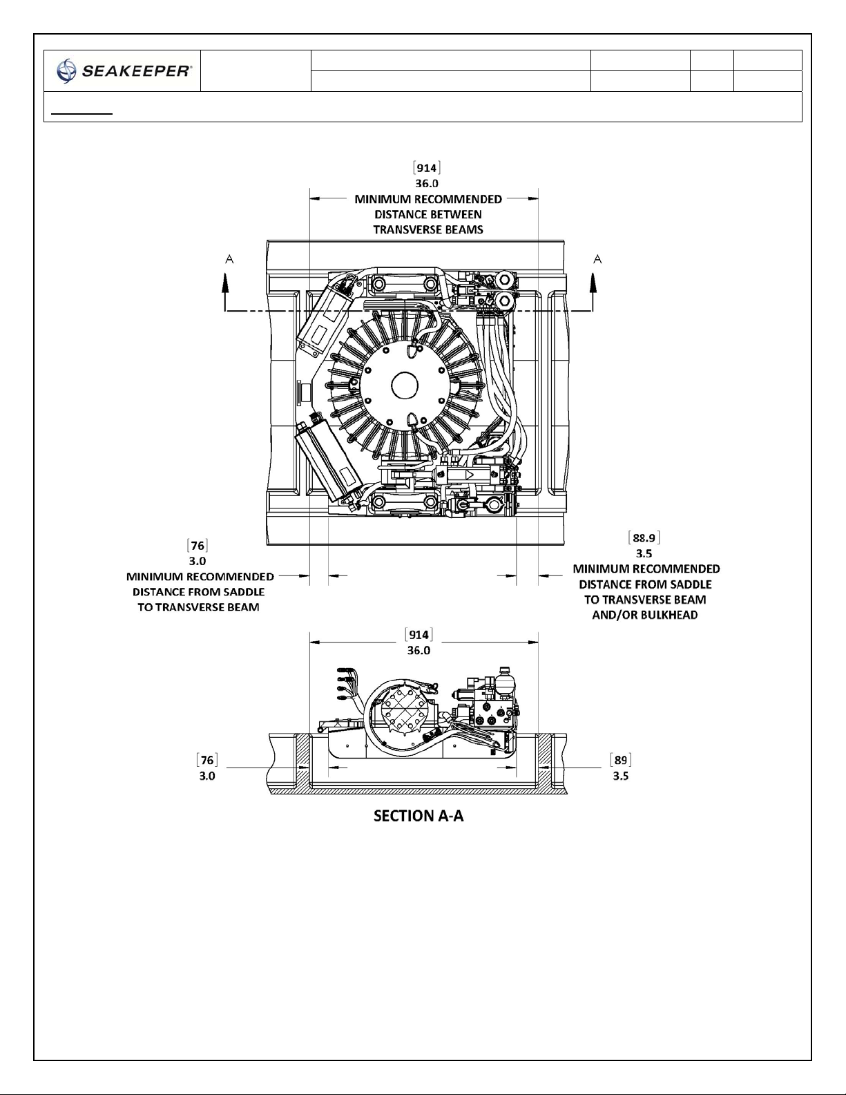
FIGURE3–TRANSVERSEBEAMSCLEARANCECONSIDERATIONS
RefertoFigure3forrecommendedclearancestotransversebeams.Ifatransversebeamislocated
undertheforwardbrace,itmustbe3”(76mm)fromtheedgeofthesaddlebeamstoprovidethe
necessaryclearancefortheswingofthemotorpowercableduringgyroprecession.Clearancesaftof
thegyroareshowntoprovideaccessformaintenance.

INSTALLATION
MANUAL
Product:Document#:Rev:Page:
MODEL5500GYRO9021425of15
Section1:MECHANICALINSTALLATION
SafetyEnclosure
Thereisalargetorqueaboutthegimbalaxiswhenthegyroisprecessing.Therefore,thegyro
mustbehousedinanenclosureoracompartmentorinstalledinacagesopersonnelorgear
cannotcomeintocontactwiththegyrowhileitisprecessing.
Thegyroshouldbetreatedwiththesamerespectonegivesahighspeedrotatingpropeller
shaftorengineshaft.
Noise/Soundproofing/Ventilation
Gyronoisehasbeenmeasuredundersteadystateconditions(nowaveload)inSeakeeper'slabandin
our43fttestboat.Thesteadystatenoiseistypicallyintherangeof70‐75dBunweighted.Asthe
frequenciesemittingthehighestsoundpressuresarelow(likeothermarinemachinery),itis
recommendedthatthegyrobeinstalledinacageinamachineryspacethatisalreadytreatedwith
soundproofing.
Ifthegyrostabilizerhastobelocatedoutsideamachineryspace,itshouldbeinstalledinasound
dampingenclosuretopreventlowfrequencynoise(approximately133Hz)fromenteringtheliving
spaces. Inthiscase,theenclosurecanbeopenatthebottombetweenthehullstringers. Asmall
exhaustfanshouldbeinstalledinthetopoftheenclosuretopullambientairthrutheenclosuresothe
airintheenclosuredoesnotheatup.Thiswillensurethattheownerdoesnotgetnuisanceshutdowns
duetotheMotorDriveandBearingtemperaturealarmsinsomeoperatingconditions(highambientair
temperature,highseawatertemperature,highseastate,etc).
Thefanshoulddeliveraminimumof35cuft/min(60cum/hr)whichshouldexchangetheairinthe
enclosureaboutonceperminute.Small,massproduced,axialandcentrifugalcoolingfansareavailable
witheitherACorDCinputpower,ballbearings,extendedtemperaturerange,lownoiseratings,long
MTBF,marinized,etc.Locatetheinletatthebottomoftheenclosureandmountthefanatthetopas
anexhaustfan.Acentrifugalfanmaybebesttominimizeoutletarea.Thefanpowerrequirements
wouldtypicallybeintherangeof20watts. WhenusingaDCfan,wireittothesamebreakerthat
providespowertotheGyroControlBoxsothefanturnsonandoffatthesametimeasthecontroller.
INSTALLATION
MANUAL
Product:Document#:Rev:Page:
MODEL5500GYRO9021426of15
Section1:MECHANICALINSTALLATION
1.3UnpackingCrate
1) ReferenceSeakeeperDrawingNo.90212,Model5500HardwareScopeofSupplyforitemsthat
shipwiththegyro.
2) Removeelectricalcomponents,cables,andmisc.itemsandsetaside.
3) Removepackingmaterialsthatsecuregyroassemblyinsidethecrate.
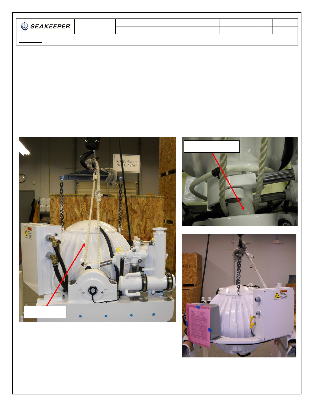
4) Attachspreaderbartothetwoliftingeyeslocatedonthetopofthegyroenclosure.Alsoattach
alevelinglinethatconnectsspreaderbartobrakegimbalshaft.Gyroweighs485kg(1069lbs).
SeeFigure4below.
FIGURE4–LIFTINGARRANGEMENT
LevelingLine
BrakeGimbalShaft

INSTALLATION
MANUAL
Product:Document#:Rev:Page:
MODEL5500GYRO9021427of15
Section1:MECHANICALINSTALLATION
1.4PreparationofHullStructure
RefertoSeakeeperDrawingNo.90219,Model5500GyroInstallationDetails.Importantdimensional
andloadinformationisgiveninthisdrawingthatwillimpactthedesigndetailsofthestructurethatwill
receivethegyroaswellasselectionofadhesivetobondthegyrointothehull.Thefoundation
“saddles”ofthegyroaredesignedtobebondeddirectlytothecompositehullstructureofthevesselto
effectivelydistributegyroscopicloads.
Notethatanypaintorgel‐coatpresentinbondareashouldberemovedsothatadhesivewillbond
directlytolaminatefibersandresin.
Acompletebondisrequiredbetweentheinsidesurfaceofthesaddlesandthehullstructure.Toaidin
determiningthequantityofadhesiverequired,thesurfaceareaofPortsaddlebondareais340in2
(2194cm2).Thestarboardsaddlebondareais310in2(2002cm2).
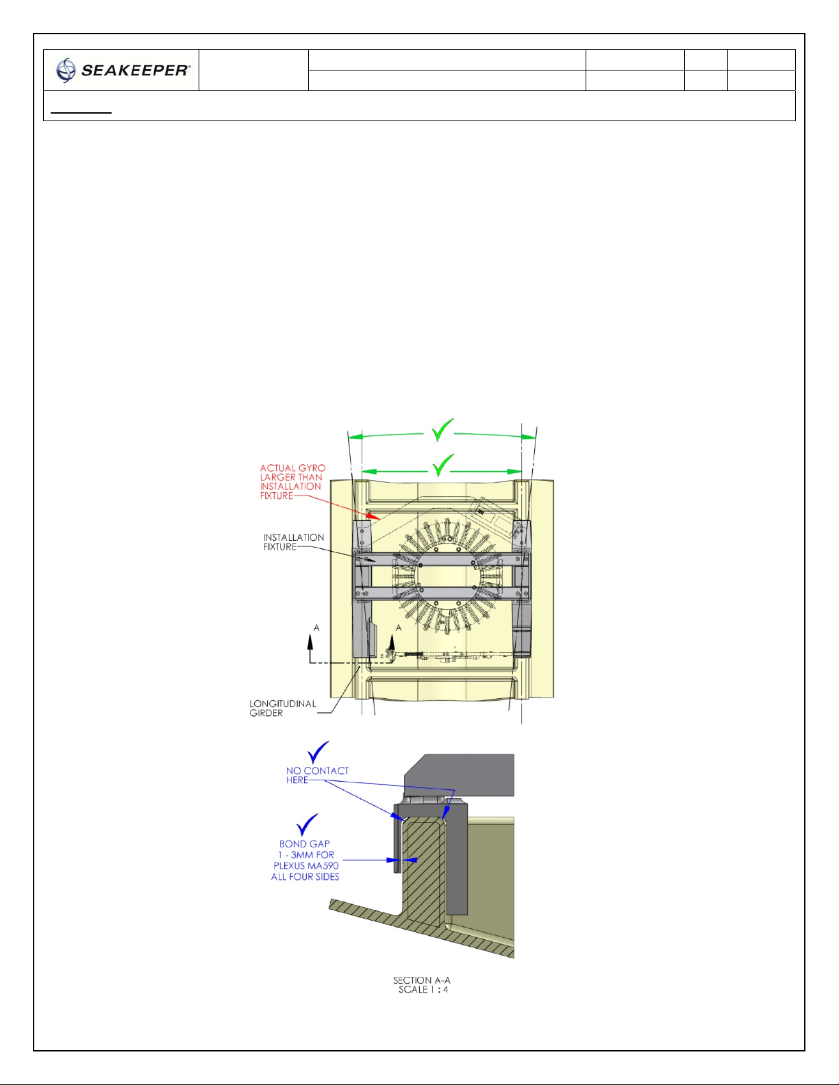
Seakeeperhasanoptionalinstallationfixtureavailable,P/N90012,thatisintendedtoduplicatethegyro
foundationgeometryinordertocheckclearancesandalignment.Thefixturewillallowthebuilder/
installertolay‐upandadjustthefoundationdimensionstocreatealow‐clearancefitbetweenthegyro
foundationsaddlesandthehullstructure.Shearstrengthoftheadhesivewillbemaximizedifthecured
thicknessbetweenthevesselstructureandgyrosaddlesisatthethinnerendoftheadhesive
manufacturersrecommendedrange.Therefore,thefixtureshouldbeusedtoconfirmthattheoverall
dimensionsofthefoundationsaresquareandlevelandthattheadhesivegapiswithintheadhesive
manufacturer’smaximumrecommendedthickness‐seeFigure5.
Thehullstructuresupportingthegyroshouldbeinstalledsothegyroisparalleltothewater‐planein
theport/starboardandforward/aftdirections.
Note:DoNOTusetheinstallationfixturetoestablishgyroenvelope
dimensions.RefertoDrawingNo.90219forenvelopedimensions.

INSTALLATION
MANUAL
Product:Document#:Rev:Page:
MODEL5500GYRO9021428of15
Section1:MECHANICALINSTALLATION
FIGURE5–INSTALLATIONFIXTURE
INSTALLATION
MANUAL
Product:Document#:Rev:Page:
MODEL5500GYRO9021429of15
Section1:MECHANICALINSTALLATION
1.4.1FiberglassHullPreparation
1) PositioninstallationjigonhullgirdersnotingrecommendedclearancesfromFigures2&3.
Checklongitudinalgirdersarealignedandspacedproperly.
Confirmfixtureislevelwhenvesselislevel.
Checkfitofsaddleovergirders.
Confirmbondgapnottoosmall,nottoolarge.
Notefixtureissmallerthanactualgyro.
FIGURE6–CHECKINGFOUNDATION
INSTALLATION
MANUAL
Product:Document#:Rev:Page:
MODEL5500GYRO90214210of15
Section1:MECHANICALINSTALLATION
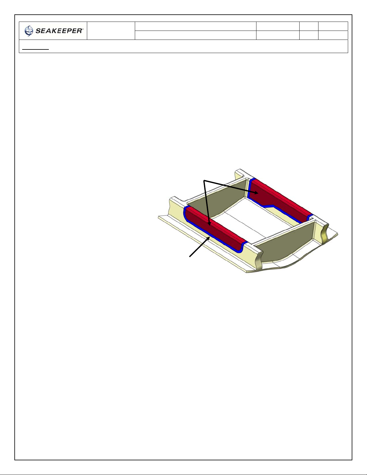
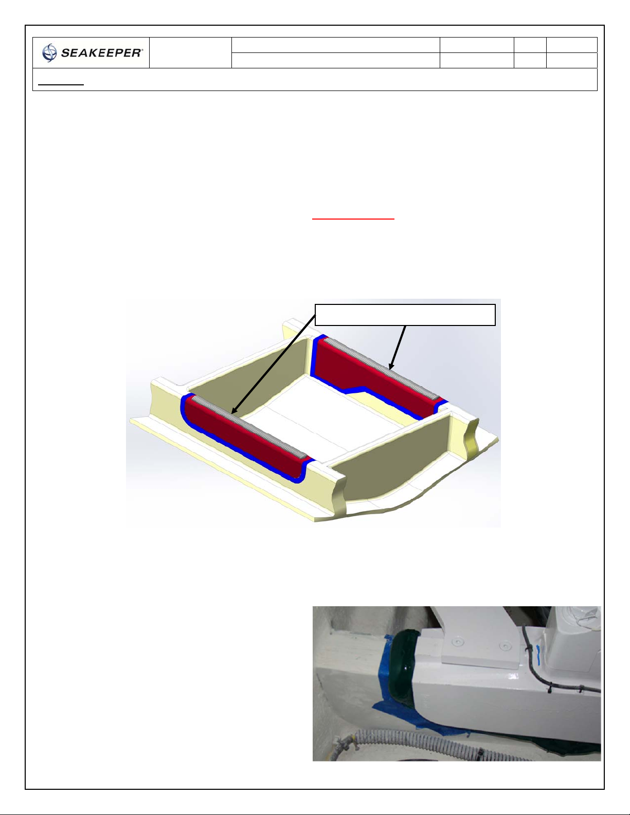
2) Maskhullareaaroundfoundationsaddlesforeasyclean‐upandtocreateoutline(highlightedin
blue)ofsurfaceareatoreceiveadhesiveasshowninred,Fig7.
3) Raisejigclearoffoundation.
4) Thoroughlycleanwithalcoholoracetoneallareas(highlightedinred,Fig7)ofgirderstobe
bondedtoremoveanycontaminates.Usenewpapertowelsforcleaning,notshoprags.
5) Removeallpaintandgel‐coatfrombondsurfacessothatadhesivewillbonddirectlytolaminate
fibersandresinasshowninFigure7.
6) Thoroughlysandgirderbond
surfaceswith80grit
sandpaper.(IMPORTANT–
BONDSTRENGTHMAYBE
REDUCEDIFTHISSTEPIS
SKIPPED.)
7) Wipesurfacescleanfromdust
withalcoholoracetoneusing
newpapertowels,notshop
rags.
8) Re‐positioninstallationjigon
girdersanddouble‐checkthat
theadhesivegapiswithinthe
adhesivemanufacturer’s
maximumrecommended
thickness.(Notegapwillbe
largerduetoabsenceofgel‐
coat.)
1.4.2Aluminum/SteelHullPreparation
1) Followsteps1‐4offiberglasshullpreparation.
2) Removealloxidationviasandingwith80gritsandpaper/grinding.(IMPORTANT–BOND
STRENGTHMAYBEREDUCEDIFTHISSTEPISSKIPPED.)
3) Wipesurfacescleanfromdustwithalcoholoracetoneusingnewpapertowels,notshoprags.
4) IfusingPlexusMA590adhesive,applyPlexusPC‐120surfaceconditionertothebonding
surfaces.Theseinstructionsarelocatedattheendofthissection.
5) ThegyroshouldbeinstalledwhenPC‐120isconfirmeddry.
Notewheninstallinggyroonaluminum/steelhull,thesandingandPC‐120(if
usingPlexusMA590adhesive)applicationforbothhullandgyrosaddles
shouldbedoneasclosetothesametimeaspossible.Thiswillminimize
oxidationonbondsurfacesandhelpimproveadhesivebondstrength.
Cleanallareasof
girderstobe
bonded–no
paint,nogel‐coat
Tapegirders
aroundfixtureto
makeclean‐up
easier FIGURE7‐MASKING&CLEANINGHULL

INSTALLATION
MANUAL
Product:Document#:Rev:Page:
MODEL5500GYRO90214211of15
Section1:MECHANICALINSTALLATION
1.5CleanGyroSaddles
1) PositionGyronearfoundation.
2) Checkthatthescrewsthatattachforward
andaftbracesaretightasthesemaintain
foundationalignmentduringbonding
process.
3) Notethateachofthesaddleshastwo
stand‐offpads(SeeFigure8)locatedon
thetopundersidesurface.DoNOT
removethesepadsastheyaremeantto
maintainasmallgapatthetopofthe
saddletoinsurethatalladhesivedoesnot
getforcedawaybytheweightofthegyro.
4) Performdryfitofgyroassemblyoverhullstructure(noadhesive)toconfirmthatfitisgood.
5) Confirmadhesivegapiswithinadhesivemanufacturer’srequirements.
6) Raisegyroclearoffoundation.
7) Thegyrocontainsholesonthesidesofthe
saddlesforinjectingadhesiveasasecondary
meansofapplyingadhesive.Thegyroshipswith
plugsintheseholes,20places.Checkthatall
plugsareinplaceasshowninFigure9.Plugs
shouldremainintheholesuntilstep1.6.2is
completed.
FIGURE9–ADHESIVEINJECTIONHOLESPLUGGED
Stand‐OffPads
FIGURE8–STANDOFFPADS

INSTALLATION
MANUAL
Product:Document#:Rev:Page:
MODEL5500GYRO90214212of15
Section1:MECHANICALINSTALLATION
8) Thoroughlycleanwithalcoholoracetonetheinsidesurfacesofgyrofoundationsaddles(see
Figure10)toremoveanycontaminates.Usenewpapertowelsforcleaning,notshoprags.
FIGURE10–FOUNDATIONPREPARATIONFORBONDING
9) Thoroughlysandallgyrobondsurfaceswith80gritsandpaper.(IMPORTANT–BOND
STRENGTHMAYBEREDUCEDIFTHISSTEPISSKIPPED.)
10) Wipesurfacescleanfromdustwithalcoholoracetoneusingnewpapertowels,notshoprags.
11) IfusingPlexusMA590adhesive,applyPlexusPC‐120surfaceconditionertoinsidesurfacesof
gyrofoundationsaddlesinaccordancewithmanufacturerinstructions.Theseinstructionsare
locatedattheendofthissection.
12) Tapeoffthecounter‐boresateachofthefourgimbalbearingbolts(4places)andholesfor
forwardbracemountingbolts(4places)tokeepadhesiveoutofscrewthreadsasshownin
Figure10.
INSTALLATION
MANUAL
Product:Document#:Rev:Page:
MODEL5500GYRO90214213of15
Section1:MECHANICALINSTALLATION
1.6InstallGyro
1) IfusingPlexusMA590adhesive,thegyroshouldbeinstalledwhenPC‐120isconfirmeddry.
Applyadhesivetothehullstructure(SeeFigure11)inamannerthatallgapsbetweenthe
saddlesandthehullstructurewillbefilledwithadhesivewhenthegyroisloweredintoposition.
ExcessadhesivewillbeneededtoinsureaCOMPLETEBOND–someadhesivewillgetsqueezed
outandmustbecleanedoffanddiscarded.IfusingthePlexusMA590AdhesiveInstallationKit
fromSeakeeper,itisrecommendedtoapply2fullcartridgestothetopofeachhullstringer.
Workdeliberateandfastasittakessometimetoapplytheadhesivetothestructure.MA590
hasa90minuteworkingtimeatroomtemperature(23°C/73°F).Thisworkingtimecanreduce
to40‐50minutesatelevatedtemperatures.
2) Oncetheadhesivehasbeenapplied,lowergyroontohullstructure.
3) Visuallyinspecttheentireperimeterofeachsaddletoconfirmthatadhesivehasfilledallthe
gapsonthesaddlesides.Ifadhesivehas
beenappliedcorrectly,itwillsqueeze
outaroundthesidesofthesaddlesas
showninFigure12.Ifadhesivehasfilled
allthegaps,gotostep6.Ifusingthe
PlexusMA590adhesivefromSeakeeper
andtheadhesivedoesnotappearin
certainareas,injectusingtheprovided
nozzleasshowninFigure13.(Note
adhesiveshowninpictureisfor
illustrativepurposesonly.MA590colorwillbegray.)
Applylargebeadontopofgirders
FIGURE11–APPLYINGADHESIVETOHULL
FIGURE12–ADHESIVESQUEEZEOUT
INSTALLATION
MANUAL
Product:Document#:Rev:Page:
MODEL5500GYRO90214214of15
Section1:MECHANICALINSTALLATION
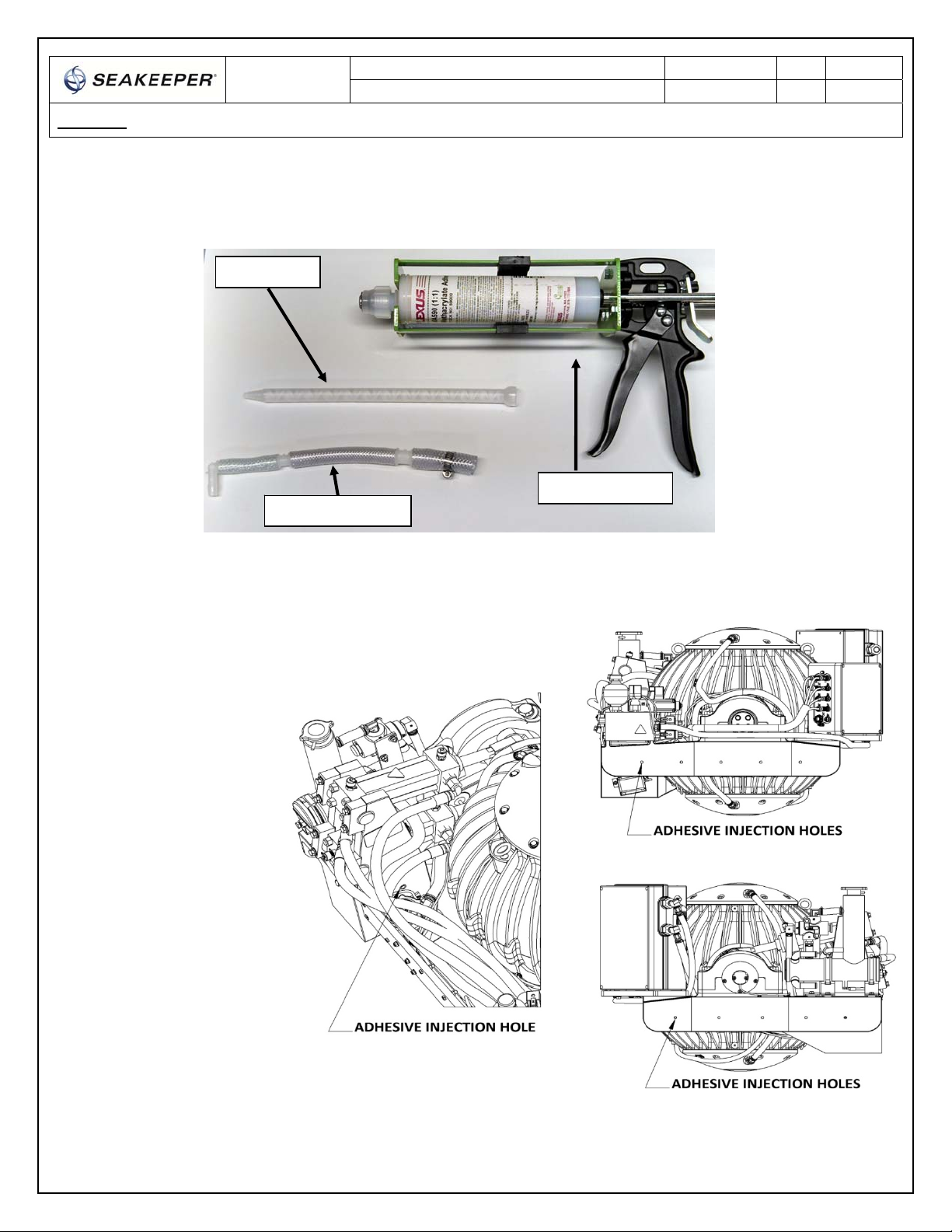
4) Attachinjectionnozzlewithclamptomixingtip.
Thereareatotalof20
adhesiveinjection
holes,with5holeson
boththeinboardand
outboardsidesof
eachsaddleasshown
inFigure14.
FIGURE14–ADHESIVEINJECTIONHOLES
FIGURE13– ADHESIVEINSTALLATIONSUPPLIES
AdhesiveGun
In
j
ectionNozzle
Mixin
g
Ti
p

INSTALLATION
MANUAL
Product:Document#:Rev:Page:
MODEL5500GYRO90214215of15
Section1:MECHANICALINSTALLATION
5) Ifneeded,insertthetipofthe
injectionnozzleintotheappropriate
holeinthesideofthesaddleas
showninFigure15.Pumpin
adhesiveuntilitfillstheobserved
gaporareathatlacksadhesiveinthe
gapbetweenthesaddlesideandthe
hullstructure.Theinjectionprocess
isonlyusedtorecoverfrom
inadequateorun‐evenadhesive
application.Thismethodshouldnot
beusedastheprimarymeansof
applyingadhesive.
6) Discardplugsandcleanupanyexcessadhesive.Allowadhesivetocurepermanufacturer’s
recommendations.DoNOToperategyrobeforeadhesivehasfullycured.
7) Afteradhesiveiscured,itisrecommendedtosealtheedgesofsaddlewithsealantorpaintto
minimizecorrosionintrusionintobondjoint.
8) Bondingofgyrointohullisnowcomplete.Proceedtoinstallationofelectricalcomponentsand
coolingplumbing.
1.7Doc#90213PlexusPC‐120ApplicationInstructions
Removeplugandinserttipof
injectionnozzleintohole
FIGURE15 –INJECTINGADHESIVE

THIS PAGE INTENTIONALLY LEFT BLANK
Table of contents
Other Seakeeper Boating Equipment manuals

Seakeeper
Seakeeper 26 User manual

Seakeeper
Seakeeper 30HD User manual

Seakeeper
Seakeeper 3 User manual

Seakeeper
Seakeeper 16 GYRO User manual

Seakeeper
Seakeeper 7000 GYRO User manual

Seakeeper
Seakeeper 7000 GYRO Service manual

Seakeeper
Seakeeper 8000 GYRO User manual

Seakeeper
Seakeeper 26000 GYRO User manual

Seakeeper
Seakeeper 1 User manual

Seakeeper
Seakeeper 3 User manual


Popular Boating Equipment manuals by other brands


Humphree
Humphree HCS-5 installation manual

Vetus
Vetus BOW4512D Operation manual and installation instructions

Dock Doctors
Dock Doctors SLIDING BOARDING STEP Assembly instructions

Mastervolt
Mastervolt Mass Combi 12/2000-100 Quick installation

SeaView
SeaView PM5-FMD-8 installation instructions

Hobie
Hobie Mirage 360 manual


