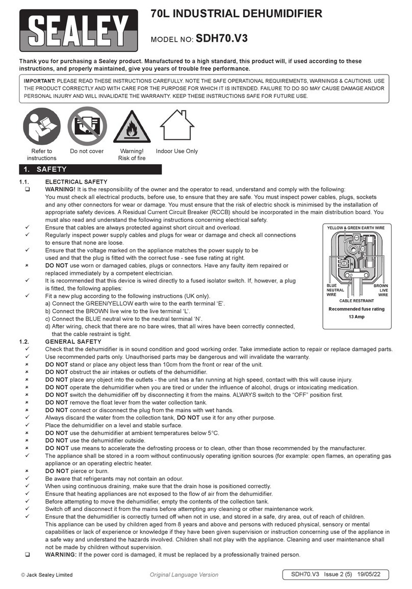
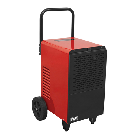
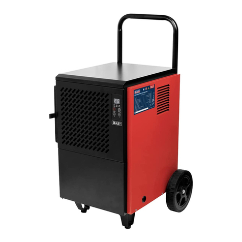
Sealey XRC25 User manual

INSTRUCTIONS FOR:
DEHUMIDIFIERS
MODEL NOS: XRC25, 40, 55 & 90
Thank you for purchasing a Sealey product. Manufactured to a high standard this product will, if used according to these instructions
and properly maintained, give you years of trouble free performance.
XRC25,40,55,90 - 1 - 060503
IMPORTANT: PLEASE READ THESE INSTRUCTIONS CAREFULLY. NOTE THE SAFE OPERATIONAL REQUIREMENTS, WARNINGS & CAUTIONS.
USE THE PRODUCT CORRECTLY AND WITH CARE FOR THE PURPOSE FOR WHICH IT IS INTENDED. FAILURE TO DO SO MAY CAUSE
DAMAGE OR PERSONAL INJURY, AND WILL INVALIDATE THE WARRANTY. PLEASE KEEP INSTRUCTIONS SAFE FOR FUTURE USE.
1.1. ELECTRICAL SAFETY
p WARNING! It is the responsibility of the owner and the operator to read, understand and comply with the following:
You must check all electrical products, before use, to ensure that they are safe. You must inspect power cables, plugs, sockets and any other
connectors for wear or damage. You must ensure that the risk of electric shock is minimised by the installation of appropriate safety devices.
A Residual Current Circuit Breaker (RCCB) should be incorporated in the main distribution board. We also recommend that a Residual Current
Device (RCD) is used. It is particularly important to use an RCD with portable products that are plugged into a supply which is not protected
by an RCCB. If in any doubt consult a qualified electrician. You may obtain a Residual Current Device by contacting your Sealey dealer.
You must also read and understand the following instructions concerning electrical safety.
1.1.1. The Electricity at Work Act 1989 requires that all portable electrical appliances, if used on business premises, are tested by a qualified
electrician, using a Portable Appliance Tester (PAT), at least once a year.
1.1.2. The Health & Safety at Work Act 1974 makes owners of electrical appliances responsible for the safe condition of those appliances
and the safety of the appliance operators. If in any doubt about electrical safety, contact a qualified electrician.
1.1.3. Ensure that the insulation on all cables and on the appliance is safe before connecting it to the power supply. See 1.1.1. and 1.1.2.
and use a Portable Appliance Tester.
1.1.4. Ensure that cables are always protected against short circuit and overload.
1.1.5. Regularly inspect power supply cables and plugs for wear or damage and check all
connections to ensure that none is loose.
1.1.6. Important: Ensure that the voltage marked on the appliance matches the power supply
to be used and that the plug is fitted with the correct fuse - see fuse rating at right.
1.1.7. DO NOT pull or carry the appliance by the power cable.
1.1.8. DO NOT pull the plug from the socket by the cable.
1.1.9. DO NOT use worn or damaged cables, plugs or connectors. Immediately have any faulty
item repaired or replaced by a qualified electrician. When a BS 1363/A UK 3 pin plug is
damaged, cut the cable just above the plug and dispose of the plug safely.
Fit a new plug according to the following instructions (UK only).
a) Connect the GREEN/YELLOW earth wire to the earth terminal E.
b) Connect the BROWN live wire to the live terminal L.
c) Connect the BLUE neutral wire to the neutral terminal N.
d) After wiring, check that there are no bare wires, that all wires have been correctly connected, that the cable outer insulation
extends beyond the cable restraint and that the restraint is tight.
Double insulated products, which are always marked with this symbol , are fitted with live (brown) and neutral (blue) wires only.
To rewire, connect the wires as indicated above - DO NOT connect either wire to the earth terminal.
1.1.10. Products which require more than 13 amps are supplied without a plug. In
this case you must contact a qualified electrician to ensure that a suitably
rated supply is available. We recommend that you discuss the installation of an
industrial round pin plug and socket with your electrician.
1.1.11. If an extension reel is used it should be fully unwound before
connection. A reel with an RCD fitted is preferred since any appliance
plugged into it will be protected. The cable core section is important and
should be at least 1.5mm2, but to be absolutely sure that the capacity of
the reel is suitable for this product and for others which may be used in the
other output sockets, we recommend the use of 2.5mm2section cable.
1. SAFETY INSTRUCTIONS
FUSE RATING 13 AMP
Blue
Neutral
Wire
Yellow & Green
Earth Wire
Cable
Restraint
Brown
Live
Wire
1.2 GENERAL SAFETY
pWARNING! Disconnect the dehumidifier from the mains power before
servicing or performing any maintenance.
3Maintain the dehumidifier in good condition (use an authorised service agent).
3Replace or repair damaged parts. Use genuine parts only. Non-authorised
parts may be dangerous and will invalidate the warranty.
3Use dehumidifier only on level and solid floors.
7DO NOT use the dehumidifier for any purpose other than that for which it
is designed.
7DO NOT operate the dehumidifier if any parts are damaged or missing as
this may cause failure and/or personal injury.
7DO NOT allow untrained persons to operate the dehumidifier.
7DO NOT use the dehumidifier where there are flammable liquids, solids or
gases such as paint solvents, etc.
7DO NOT pull the cord from the power supply.
3When not in use switch off the dehumidifier, remove plug from the power supply.

MODEL NO . .Units of measurement/spec. .XRC25 . . . . .XRC40 . . . .XRC55 . . . .XRC90
Electrical power . . . . . . . . . . .W . . . . . . . . . . . . . 650 . . . . . . . . .800 . . . . . . . .831 . . . . . . . .1205
Max. current . . . . . . . . . . . . . .A . . . . . . . . . . . . . .3 . . . . . . . . . . .4 . . . . . . . . . .5 . . . . . . . . . .7
Drying capacity . . .30OC / 80%RH (L / 24H) . . . . .23 . . . . . . . . . .42 . . . . . . . . .53 . . . . . . . . .88
. . . . . . . . . . . . . .27OC / 60%RH (L / 24H) . . . . .11 . . . . . . . . . .27 . . . . . . . . .37 . . . . . . . . .54
. . . . . . . . . . . . . .12OC / 70%RH (L / 24H) . . . . .5 . . . . . . . . . . .7 . . . . . . . . . .18 . . . . . . . . .22
Working range (Humidity) . . .%. . . . . . . . . . . .40 -100 . . . . . .40 -100 . . . . .40 -100 . . . . .40 -100
Working range (Temperature) OC. . . . . . . . . . . . .5 - 30 . . . . . . .5 - 30 . . . . . . .5 - 30 . . . . . . .5 - 30
Air flow . . . . . . . . . . . . . . . .m3/h . . . . . . . . . . . .350 . . . . . . . . .500 . . . . . . . .600 . . . . . . . .800
Cooling gas type . . . . . . . . .Gas . . . . . . . . . . .R407C . . . . . .R407C . . . . . .R407C . . . . . .R407C
Cooling gas mass . . . . . . . . .(g) . . . . . . . . . . . . .350 . . . . . . . . .500 . . . . . . . .525 . . . . . . . .700
Compressor . . . . . . . . . . . . . . . . . . . . . . . . .Reciprocating . . . .Rotary . . . . . .Rotary . . . . . .Rotary
Container full LED . . . . . . . . . . . . . . . . . . . . . . . .Yes . . . . . . . . .Yes . . . . . . . .Yes . . . . . . . .Yes
Compressor protection . . . . . . . . . . . . . . . . . . . . .Yes . . . . . . . . .Yes . . . . . . . .Yes . . . . . . . .Yes
Filter . . . . . . . . . . . . . . . . . . . . . . . . . . . . . . . . . .Yes . . . . . . . . .Yes . . . . . . . .Yes . . . . . . . .Yes
Tank capacity . . . . . . . . . . .Litres . . . . . . . . . . . .10 . . . . . . . . . .10 . . . . . . . . .10 . . . . . . . . .10
Weight . . . . . . . . . . . . . . . . .Kg . . . . . . . . . . . . .34 . . . . . . . . . .51 . . . . . . . . .57 . . . . . . . . .63
Dimensions . . . . . . . . . . . . .mm . . . . . . . . .455x370x635 .540x460x860 .970x670x650 .985x700x700
3. TRANSPORT & ASSEMBLY
4. INSTALLATION
2. INTRODUCTION & SPECIFICATIONS
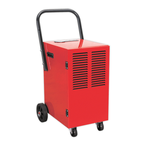
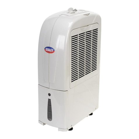
The XRC commercial/industrial dehumidfier range is designed to remove moisture from the air in high humidity environments such as cellars,
kitchens, bathrooms etc. The units are designed for continuous operation either manually or automatically if connected to an optional hygrostat
sensor. The internal cooling units use the more environmentally friendly R407C cooling gas. All units have an air filtering system, electronic
control, a defrost system for compressor protection, and an automatic stop when the water collection tank is full. The units are easy to move
and robustly constructed.
3.1 Transit. The unit should be transported in a vertical position or inclined on the handle
side. If it has been transported in a horizontal position allow the unit to stand in the
vertical position for about one hour to allow the lubrication to be rebalanced.
3.2 Check that the unit has not been damaged in any way and that all parts are present. If
there are any problems contact your local Sealey dealer.
3.3 Packaging. Packaging materials such as cartons, polythene bags etc should not be
left within the reach of children as such items could be dangerous to them. Dispose of
all packaging materials in accordance with local authority requirements.
3.4 Assembly. Assemble the main handle to the body of the unit as shown in fig.1 using
the fixing screws provided.
fig.1
fig. 4
4.1 It is important that the air inlet and air outlet remain unobstructed at all times.
4.2 The following minimum safety distances are recommended between the unit and
walls or objects.
Ÿ
Minimum distance from air inlet - 0.6m.
Ÿ
Minimum distance from air outlet - 3.0m.
4.3 Ideally the unit should be installed in the centre of the room to guarantee the best
possible air circulation.
4.4 DO NOT install the unit near heat sources. Keep windows and doors closed whilst the
unit is operating.
4.5 Dual voltage models (XRC55 & 90). The dual voltage models are designed to run off
either a 230V 50Hz supply or a 110V 50Hz supply. To select the required voltage do
the following:
Ÿ
Remove the two fixing screws holding the voltage selector cover plate.
Ÿ
Move the selector switch to the required voltage.
Ÿ
Reverse the cover plate and screw it back into position.
4.6 Water drain. Drained water can be collected and eliminated in 2 ways:
A) Using the tank supplied as shown in fig.2. The tank must be emptied when the yelow tank full LED lights up. Switch the unit off
before emptying the tank and disconnect the mains plug. Remove the tank carefully to avoid spills and empty it. Slide the tank back
into the unit ensuring that the level sensor is correctly placed within the tank.
NOTE: When the dehumidifier is switched off and then restarted, the compressor will not start to run immediately but will cut in again
after some minutes. This waiting time protects the compressor from repeated starts at short intervals.
B) Water may be removed by connecting a plastic hose with an internal diameter of 14mm to the hose holder in the drain
compartment. ( Plastic hose not supplied.) See fig.3.
Special attention should be paid not to raise the outlet of the hose over the drain level of the unit. (Max height 1ft, see fig.4) Failure to
do this will result in water spillage and flooding of the unit.
4.7 Connection of a Hygrostat. A hygrostat control is also available as an optional accessory. This enables the unit to function automatically.
The remote hygrostsat will be located near the air inlet and is connected to the unit via a jack plug on the units control panel
fig. 2
fig. 3
XRC25,40,55,90 - 1 - 060503

5. OPERATION
6. MAINTAINANCE
5.1 Dual Voltage Models XRC55 & XRC90. Before operating the
unit ensure that the correct voltage has been selected.
5.2 Continuous operation in manual mode.
5.2.1 Connect the unit to the mains power supply.
5.2.2 Switch the unit on by moving the on/off switch to the I position at
which point the switch should illuminate. After a few minutes the
green LED on the control panel will illuminate indicating that the
compressor has started. In this mode the unit will dry the air
continuously until the unit is switched off again.
5.2.3 To switch the unit off move the on/off switch to the O position.
5.3 Automatic operation using a remote hygrostat. (Optional)
5.3.1 Connect the unit to the mains power supply.
5.3.2 Connect the hygrostat lead to the jack socket on the units control
panel. Switch the unit on. After a few minutes the green LED will
illuminate and the compressor will start to rotate. Set the desired
level of humidity on the hygrostat. If the general humidity is
higher than the preset value the unit will start to operate. When
the humidity has reached the preset value the compressor will be
switched off automatically but the fan will continue to operate.
When the air humidity increases above the preset value the
compressor will cut in again. This automatic cycling will continue
until the unit is switched off.
5.4 Electronic control.
5.4.1 Each dehumidifier is equiped with an electronic control
unit with related LED display panel which can be seen on the
rear of the dehumidifier. The functions of the LEDs are as
follows, (see fig.6).
5.4.2 ORANGE LED. The room temperature is too low or the unit
is in defrost mode.
5.4.3 RED LED. The room temperature is too high or a reduction
of air flow has occurred. Check filter and remove obstructions to
air flow if required. Check that the fan is rotating.
5.4.4 YELLOW LED. The water tank is full. Empty tank or check pump.
5.4.5 GREEN LED. The compressor is running.
6.1 Unplug the unit from the power supply before carrying out any maintenance or service.
6.2 Cleaning the filter. To maintain the efficiency of the unit wash the filter in luke warm water on a regular basis.
6.3 Cleaning the unit. Clean the unit at least once a year. Remove air filter, remove front and rear panels to gain access to inner
parts. Clean inner parts using compressed air paying particular attention to the condenser, evaporator and water drainage tray.
fig. 6
NOTE: It is our policy to continually improve products and as such we reserve the right to alter data, specifications and component parts without prior notice.
IMPORTANT: No liability is accepted for incorrect use of this product. WARRANTY: Guarantee is 12 months from purchase date, proof
of which will be required for any claim. INFORMATION: Call us for a copy of our latest catalogue on 01284 757525 and leave your full name
and address including your postcode.
01284 757500
01284 703534 sales@sealey.co.uk
Sole UK Distributor
Sealey Group,
Bury St. Edmunds, Suffolk.
www.sealey.co.uk
Web
email
Declaration of Conformity We, the sole importer into the UK, declare that the products listed below are in conformity withthe following standards and directives.
The construction files for these products are held by the Manufacturer and may
be inspected, by a national authority, upon request to Jack Sealey Ltd.
For Jack Sealey Ltd. Sole importer into the UK of Sealey Power Tools.
Signed by Mark Sweetman 14th April 2003
Dehumidifiers
Models XRC25, 40, 50 & 90
73/232/EEC Low Voltage Directive
89/336/EEC EMC Directive
XRC25,40,55,90 - 1 - 060503
This manual suits for next models
3
Table of contents
Other Sealey Dehumidifier manuals

Sealey
Sealey SDH30 User manual

Sealey
Sealey SDH101 User manual

Sealey
Sealey SDH102.V2 User manual

Sealey
Sealey SDH50110V User manual

Sealey
Sealey SDH30.V2 User manual

Sealey
Sealey SDH50.V3 User manual

Sealey
Sealey SDH70 User manual

Sealey
Sealey SDH20.V5 User manual

Sealey
Sealey SDH90 User manual

Sealey
Sealey SDH20.V4 User manual