3. SPECIFICATION
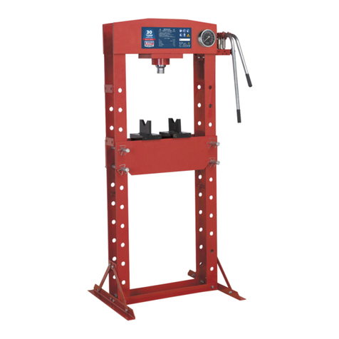
Model No: ............................................................ YK759F.V3
Bench or Floor Mounting:...............................................Floor
Capacity:................................................................... 75tonne
Gauge Included:............................................................... Yes
Lateral Ram Travel:.................................................... 260mm
Maximum Height-Ram to Table: ................................. 884mm
Minimum Height-Ram to Table: .................................. 170mm
Optional Accessories: ............................................................
................... YKSG75 - Safety Guard, YKPP8 - Press Pin Set
Overall Height: ......................................................... 1925mm
Ram Diameter:.......................................................... Ø93mm
Ram Stroke:............................................................... 250mm
Table Aperture:.................................................... 251/201mm
Type: ....................................................................... Hydraulic
Working Table Depth:................................................. 279mm
Working Table Width: ............................................... 1020mm
4. ASSEMBLY
Unpack the product and check contents. Should there be any damaged or missing parts contact your supplier immediately.
▲DANGER! Take care to ensure safety when moving main frame from packing as the unit is very heavy. Use a suitable hoist or
gantry.
Refer to attached parts list.
Seek assistance from another person on assembly of heavy parts.
Assemble press, if possible, in close proximity to where the press will be located.
4.1. FRAME ASSEMBLY
4.1.1. Attach load slings around the top cross member of the frame and using a suitable hoist or gantry, slowly, and in a controlled
manner lift the frame up and out of the transportation crate, into an upright position.
WARNING! Take care when lifting the frame not to damage the pre-assembled ram assembly, pump assembly, bed frame
assembly and winch assembly.
4.1.2. Keep the frame assembly in an upright position, held safely by the load slings.
▲DANGER! DO NOT allow the frame to fall over.
4.1.3. Position base section (#1) and secure with M12 x 35 hex head set screw (#2), M12 flat washer (#6), M12 spring washer (#5)
and M12 nut (#4) loosely.
4.1.4. Repeat for other side base section (#1).
4.1.5. Position the supports (#3) to base section (#1) and frame (#43) and secure with M12 x 35 hex head set screw (#2), M12 flat
washer (#6), M12 spring washer (#5) and M12 nut (#4) loosely.
4.1.6. Repeat for other side supports (#3).
4.1.7. On a flat level floor, level the frame using a good quality spirit level. Fully tighten all fixings.
WARNING! Take care and seek assistance from another person when lowering and levelling the frame assembly onto the floor.
4.2. ATTACH THE WINCH ASSEMBLY
WARNING! Seek assistance from another person with this task as the hand winch assembly is heavy.
4.2.1. Transfer the hand winch assembly (#12, #13) from its transport location by firstly removing the fixings M12 x 35 hex head set screw
(#2), M12 flat washer (#6), M12 spring washer (#5) and M12 nut (#4) from hand winch support (#13). Retain the fixings.
4.2.2. Move the hand winch assembly (#12, #13) to the outside of the left hand post (position H on the parts diagram) and secure with the
retained fixings, loosely.
4.2.3. Ensure that the cables are correctly located in the rollers prior to fully tightening fixings.
4.3. ATTACH THE PUMP ASSEMBLY
WARNING! Seek assistance from another person with this task as the pump assembly is heavy.
4.3.1. Transfer the pump (#53) assembly from its transport location by firstly removing the fixings, hex head screw M10 x 45 (#54) and
M10 flat washer (#15). Retain the fixings.
4.3.2. Attach the pump (#53) assembly in position at the top, right hand side of frame (#43) and secure with the retained fixings.
4.4. ATTACH THE HANDLE
4.4.1. Remove the locking fixings hex head screw M8 x 20 (#62) and M8 flat washer (#63) from the handle (#61) and retain.
4.4.2. Insert the handle into the pump handle holder and secure with the retained fixings.
4.5. ATTACH THE PRESSURE GAUGE
NOTE: The pressure gauge and fittings are supplied pre-assembled.
4.5.1. Remove half nut M20 x 1.5 fine pitch (#52) from gauge fitting (#51) and retain.
4.5.2. Insert gauge fitting assembly through hole in top right side of frame at position A on the parts diagram.
4.5.3. Secure into place with half nut M20 x 1.5 fine pitch (#52).
4.6. ATTACH THE PUMP HOSE.
NOTE: The short hose A (#56) is pre-assembled to the pump (#53).
4.6.1. Remove the dust plug from the end of short hose (#56).
4.6.2. Attach hose to pressure gauge fitting (#51) at position A on the parts diagram.
4.7. ATTACH THE OIL HOSE
NOTE: The oil hose B (#58) is pre-assembled to the ram (#46).
4.7.1. Remove the dust plug from the end of oil hose (#58).
4.7.2. Remove the dust plug from the oil filler nut (#70) and attach the oil hose, at position B on the parts diagram.
YK759F.V3 Issue 1 08/12/21
Original Language Version
© Jack Sealey Limited
