Sealey TS12CZ.V2 User manual

INSTRUCTIONS FOR:
CONTRACTOR’S SAW 315mm 230V
Model: TS12CZ.V2
Thank you for purchasing a Sealey product. Manufactured to a high standard this product will, if used according to these instructions
and properly maintained, give you years of trouble free performance.
1. SAFETY INSTRUCTIONS
IMPORTANT: PLEASE READ THESE INSTRUCTIONS CAREFULLY. NOTE THE SAFE OPERATIONAL REQUIREMENTS, WARNINGS AND
CAUTIONS. USE THIS PRODUCT CORRECTLY AND WITH CARE FOR THE PURPOSE FOR WHICH IT IS INTENDED. FAILURE TO DO SO MAY
CAUSE DAMAGE AND/OR PERSONAL INJURY AND WILL INVALIDATE THE WARRANTY. PLEASE KEEP INSTRUCTIONS SAFE FOR FUTURE USE.
1.1. ELECTRICAL SAFETY
! WARNING! It is the user’s responsibility to read, understand and comply with the following:
You must check all electrical equipment and appliances, before using, to ensure that they are safe. You must inspect power supply leads, plugs
and all electrical connections for wear and damage. You must ensure the risk of electric shock is minimised by the installation of appropriate
safety devices. An RCCB (Residual Current Circuit Breaker) should be incorporated in the main distribution board. We also recommend that an
RCD (Residual Current Device) is used with all electrical products. It is particularly important to use an RCD with portable products that are
plugged into an electrical supply not protected by an RCCB. If in doubt consult a qualified electrician. You may obtain a Residual Current Device
by contacting your Sealey dealer. You must also read and understand the following instructions concerning electrical safety.
1.1.1. The Electricity At Work Act 1989 requires all portable electrical appliances, if used on business premises, to be tested by
a qualified electrician, using a Portable Appliance Tester (PAT), at least once a year.
1.1.2. The Health & Safety at Work Act 1974 makes owners of electrical appliances responsible for the safe condition of the appliance
and the safety of the appliance operator. If in any doubt about electrical safety, contact a qualified electrician.
1.1.3. Ensure the insulation on all cables and the product itself is safe before connecting to the mains power
supply. See 1.1.1. & 1.1.2. above and use a Portable Appliance Tester (PAT).
1.1.4. Ensure that cables are always protected against short circuit and overload.
1.1.5. Regularly inspect power supply leads, plugs for wear and damage and power connections, to
ensure that none is loose.
1.1.6. Important: Ensure the voltage marked on the product is the same as the electrical power supply
to be used, and check that plugs are fitted with the correct capacity fuse. A 13 amp plug may require
a fuse smaller than 13 amps for certain products, see fuse rating at right.
1.1.7. DO NOT pull or carry the appliance by its power supply lead.
1.1.8. DO NOT pull the plug from the socket by the power cable.
1.1.9. DO NOT use worn or damage leads, plugs or connections. Immediately replace or have repaired by
a qualified electrician. A U.K. 3 pin plug with ASTA/BS approval is fitted. In case of damage, cut it off
and fit a new plug according to the following instructions (discard old plug safely).
(UK only - see diagram at right). Ensure the unit is correctly wired via a three-pin plug.
a) Note that this saw is double insulated and therefore there is no GREEN/YELLOW earth wire.
b) Connect the BROWN live wire to live terminal ‘L’.
c) Connect the BLUE neutral wire to the neutral terminal ‘N’.
d) After wiring, check that there are no bare wires, that all wires have been correctly connected, that the cable outer insulation
extends beyond the cable restraint and that the restraint is tight.
Double insulated products are fitted with live (BROWN) and neutral (BLUE) wires only. Double insulated products are always marked with
this symbol . To re-wire, connect the brown & blue wires as indicated above. DO NOT connect the brown or blue to the earth terminal.
1.1.10. Some products require more than a 13 amp electrical supply. In such a case, NO plug will be fitted. You must contact a qualified electrician
to ensure a 30 amp fused supply is available. We recommend you discuss the installation of a industrial round pin plug and socket with your electrician.
1.1.11. Cable extension reels. When a cable extension reel is used it should be fully unwound before connection. A cable reel with an RCD
fitted is recommended since any product which is plugged into the cable reel will be protected. The section of the cores of the cable
is important and should be at least 1.5mm2, but to be absolutely sure that the capacity of the cable reel is suitable for this product and
for others that may be used in the other output sockets, we recommend the use of 2.5mm2section cable.
1.2. GENERAL SAFETY
#Familiarise yourself with the applications, limitations and potential hazards of the saw.
!WARNING! Disconnect the saw from the mains power before changing accessories, servicing or performing any maintenance.
#The machine must only be serviced by a qualified person or service agent. Contact your Sealey dealer for information.
#Select a work area suitable for the saw and keep the area clean, tidy and free from unrelated materials. Ensure that there is adequate lighting.
#Stand the saw on a stable floor strong enough to take the weight of the machine and workpiece.
#Wood dust can be harmful to health by inhalation and skin contact and concentrations of small dust particles in the air can form an
explosive mixture. Ensure that there is adequate ventilation and that the saw is attached to a dust-extraction unit.
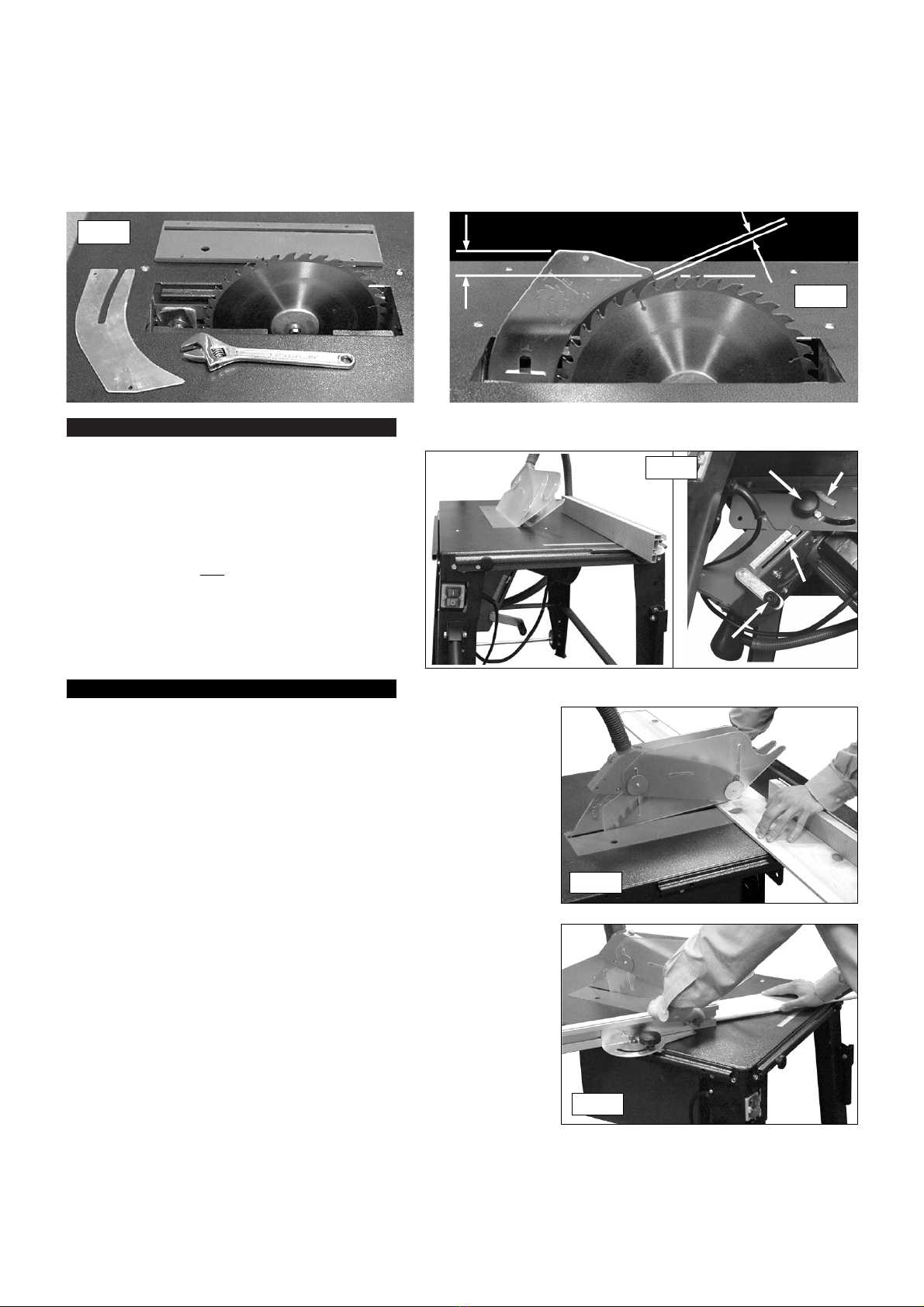
#Maintain the saw in good condition, check moving parts alignment regularly. Keep saw blades clean and sharp. ,
#Replace or repair damaged parts. Use recommended parts only. Unauthorised parts may be dangerous and will invalidate the warranty.
!WARNING! Keep all guards in place and in good working order. Check regularly for damaged parts.
A guard, or any other part, that is damaged must be repaired or replaced before the saw is next used. The safety guard is a mandatory
fitting where the saw is used on premises covered by the Health & Safety at Work Act.
#Before commencing work, ensure that the saw blade is set to cut in the correct direction, securely fastened, sharp and is compatible with the
machine, spindle speed and the material to be cut. Never use a saw blade if damaged, bent or warped. Use only recommended saw blades.
#Remove adjusting keys and wrenches from the machine and the vicinity before switching on.
#Machine operators must have received sufficient training and instructions relating to the dangers associated with the machine, the
precautions to be observed and those requirements of the Wood Working Machines Regulations which apply. Inexperienced operators must
be under the adequate supervision of a person who has a thorough knowledge and experience of the machine and the required guards.
$DO NOT operate the saw if any parts are damaged or missing as this may cause product failure and/or personal injury.
$DO NOT operate the saw when you are tired or under the influence of alcohol, drugs or intoxicating medication.
#When not in use, switch off the saw and unplug from the power supply.
TS12CZ.V2 - 1 - 080107
FUSE RATING 13 AMP
Blue
Neutral
Wire
Yellow & Green
Earth Wire
Cable
Restraint
Brown
Live
Wire

2. INTRODUCTION & DESCRIPTION
!WARNING! Wear approved safety eye protection, ear defenders and respiratory protection.
#Remove ill fitting clothing. Remove ties, watches, rings and other loose jewellery and contain long hair.
#Keep hands and body clear of the blade when operating the saw.
#Maintain correct balance and footing. Ensure the floor is not slippery and wear non-slip shoes.
#Keep children and unauthorised persons away from the work area.
#Avoid unintentional starting and never leave the saw operating unattended.
$DO NOT use the saw for a task it is not designed to perform and ensure that operators are trained to use the saw.
$DO NOT get the saw wet or use in damp or wet locations or areas where there is condensation.
$DO NOT use the saw where there are flammable liquids, solids or gases such as paint solvents and including waste cleaning rags etc.
1.3. SPECIFIC SAW SAFETY RULES
#Connect to a suitable extraction system. Failure to do so will result in the build-up of sawdust which will become a fire hazard.
#Keep riving knife and blade guard in place and operational, and replace table insert when worn.
#Ensure that the saw blade is suitable for the material to be cut.
!WARNING! Before each use, check that the saw blade is secure and not worn or damaged.
#Use the blade guard for all “through-sawing” operations. Through-sawing operations are those where the blade cuts completely through the
workpiece as in ripping or cross-cutting.
#Check workpiece to ensure that there are no nails or other items which may foul the saw blade.
#Hold the work firmly against the fence bar.
#Only feed the workpiece into the blade against the rotation of the blade.
#Avoid subjecting the saw blade to excessive strain - never force the workpiece. Maintain a controlled, steady progression.
#Should the saw blade jam, switch the power off immediately to prevent damage to the motor.
#To avoid “kickback” (when a workpiece is violently thrown back towards the operator) implement the following:
a) Keep the blade sharp. b) Keep the fence parallel to the saw blade. c)DO NOT release the workpiece before it is pushed all the way
past the saw blade. d) DO NOT rip work that is twisted or warped or does not have a straight edge to guide along the fence.
#Use a push stick for ripping narrow stock.
#Provide adequate support to the rear and sides of the saw table for long or wide workpieces.
$DO NOT use your hands alone (“free-hand”) to guide the workpiece. Hold work firmly against the fence bar to guide work through the saw.
$DO NOT place yourself in an awkward operating position where a slip could cause your hand to move into the blade.
$DO NOT stand, or have any part of your body, in line with the path of the saw blade.
$DO NOT use the fence as a cut-off gauge when cross-cutting.
$DO NOT hold what will become the off-cut (the waste part of the workpiece).
!WARNING! DO NOT reach behind or over the saw blade.
!WARNING! DO NOT attempt to free a jammed saw blade without first switching off and removing the plug from the mains power supply
and ensure that the blade has come to a complete stop.
$DO NOT cut metals or substances that may produce toxic dust. Saw must only be used to cut wood or wood derived materials.
$DO NOT attempt to cut round section wood.
$DO NOT use solvents to clean plastic parts. Use a soft damp cloth only.
#Store saw and blades in a safe, dry childproof location.
CONTENTS:
1 Main saw table (with motor/saw box
attached plus wired on/off switch)
2 Table extension (1)
3 Table extension struts (2)
4 Leg with switch aperture (1)
5 Standard leg (3)
6 Leg struts (long ) (2)
7 Leg struts (short) (2)
8 Wheel parts - Wheels (2)
9 - Wheel brackets (2)
10 - Axle (1)
11 - Circlips (4)
12 Handle parts - Handle tubes (2)
13 - Brackets (2)
14 - Bolts M13 x 50 (2)
15 - Nuts M13 (2)
16 Fence guide (1)
17 Sliding guide (1)
18 Angle ruler (1)
19 Sliding plate (1)
20 Fence (aluminium) (1)
21 Blade guard (1)
22 Riving knife (1)
23 Saw table insert (1)
24 Dust extraction pipe (1)
25 Dust extraction duct (1)
26 Dust extraction pipe bracket (1)
27 Pack of fixings (1)
28 Push stick (1)
TS12CZ.V2 - 1 - 080107
fig. 1
MAIN SAW
TABLE
TABLE
EXTENSION
DUST EXTRACTION PIPE BLADE GUARD
FENCE
ON/OFF
SWITCH
TRANSIT
HANDLES
TRANSIT
WHEELS
DUST EXTRACTION DUCT
TABLE
EXTENSION
STRUTS
Fully approved to CE regulations this 315mm contractor’s saw is full of features and ideal for the serious enthusiast and professional
workshop. Fitted with no-volt release safety switch, extended outfeed table and dust extraction. Full blade tilt up to 45°, with a maximum cut of
90mm at 90°. Fitted with handle and wheels for easy manoeuvrability around the workshop. Includes sliding carriage.

4. ASSEMBLY
!WARNING! ENSURE THAT THE SAW IS NOT
CONNECTED TO THE MAINS POWER BEFORE
COMMENCING ASSEMBLY.
4.0. Fixings. Most of the saw is assembled using M6
nuts, bolts and washers. To tighten these fixings you
will need two 10mm spanners.
Unless otherwise stated, where the text refers to
‘a set of fixings’ this will mean
- 1 M6 x 16mm hex headed bolt
- 1 M6 flat washer (diameter 18mm)
- 1 M6 lock nut
4.1. Saw stand.
The main saw stand will be assembled upside down on a suitable clean/flat surface. If necessary place some protective material down
first. Place the main table with the blade/motor box attached upside down on the surface so that there is room to subsequently fix
the table extension to it. The corners of the table are labelled 3,4,5 & 6 and these numbers will be matched to the corresponding
numbers on the legs.
Motor . . . . . . . . . . . . . . . . . . . . . . . . 2000W - 230V
Speed . . . . . . . . . . . . . . . . . . . . . . . . . . . . .2950rpm
Saw Blade . . . . . . . . . . . . . . . . .Ø315 x Ø30 x 3mm
Max. Depth of 90OCut . . . . . . . . . . . . . . . . . .90mm
Max. Depth of 45OCut . . . . . . . . . . . . . . . . . .60mm
Main Table . . . . . . . . . . . . . . . . . . . . .800 x 550mm
Output Table . . . . . . . . . . . . . . . . . . . .800 x 400mm
Dust Extraction Port . . . . . . . . . . . . . . . . . . .Ø28mm
3. SPECIFICATION
3.1. Specification
leg 3
leg 4
leg 5
F
dust extraction
duct
leg strut
(long)
leg strut
(short)
leg 6
fig. 2
fig. 3 fig. 4 fig. 5
F
F
F
push
stick
hook
leg
leg
leg
4.2 Match leg 3 to the corresponding numbered label attached to the side of the main table (See fig.3.) Use only sets of fixings at
positions 3A and 3B at this stage. The other two fixing points will be shared with the fence guides which are fitted later.
4.3 Mount the switch unit to leg 3 using two self tapping screws (ST4. 2x13mm as indicated at ‘A’ in fig.3).
4.4 Attach leg 4 as shown in fig.4. Use 3 sets of fixings at positions 4A, 4B & 4C at this stage.
4.5 Attach leg 5 as shown in fig.5 using 4 sets of fixings in positions 5A, 5B, 5C & 5D.
4.6 Attach leg 6 as shown in fig.6 using 2 sets of fixings at positions 6C & 6D. At the same time attach the dust extraction pipe bracket
which uses the same fixing positions. The other two fixing points will be shared with the table extension which is fitted later.
4.7 Assemble a short leg strut between legs 3 & 4 and between legs 5 & 6 using a single set of fixings at each end of each strut (see fig.2)
Ensure that the bent metal edges of the struts will be facing the floor when the unit is turned the right way up.
4.8 Assemble a long leg strut between legs 3 & 5 and between legs 4 & 6 using a single set of fixings at each end of each strut (see fig.2)
Ensure that the bent metal edges of the struts will be facing the floor when the unit is turned the right way up.
4.9 Where the struts overlap each other on the inside of each leg (four places) bolt them together with a single set of fixings. (See ‘F’ in fig.2)
4.10 If required, extend the length of the table by bolting the table extension to the end of the main table as shown in fig.2 & 6. The extension
is offset towards leg 6 and shares two of the leg fixings. Use 3 sets of fixings in positions 6A, 6B and at position ‘F’ as shown in fig.6.
4.11 Attach the two bracing struts between the outer edge of the extension and the adjacent leg cross brace as shown in fig.2. Use a single
set of fixings at each end of each strut.
4.12 Attach fence guide (97) to the front table edge between legs 3 &
4 using two brackets (98) and supplied screw fixings etc.
4.13 Attach the sliding guide (63) to the long side of the table edge
adjacent to the switch leg using supplied nuts and bolts etc.
4.14 Attach the dust extraction duct (part no.38) to the lower face of the red box
enclosing the blade using 4 bolts M4 x 12mm. See fig.2.
fig. 6
leg
table extension dust extraction
pipe bracket

5. FITTING / CHANGING THE BLADE
TS12CZ.V2 - 1 - 080107
4.15 Attaching the wheels. The wheels, axle and wheel brackets should be assembled as shown in fig.2. The wheel brackets are ‘handed’
and should be orientated as shown in fig.7. Take the wheel axle and attach two circlips to the two grooves nearest to the centre of the
axle. Slide a wheel over each end of the axle followed by the correct bracket. Retain the wheels and brackets by attaching another
circlip to each end of the axle.
4.16 Attach the wheel brackets to legs 5 & 6 respectively using two sets of fixings for each bracket as shown in fig.7. Leave the fixings
loose at this stage.
4.17 Final tightening of bolts. Prior to turning the machine upright, finally tighten all bolts except those holding the wheel brackets.
4.18 Turn the saw over to stand upright. Do not do this on your own but get someone to help you as the machine is too heavy and large for
one person to lift and manoeuvre.
4.19 Loosen the wheel brackets slightly and position the wheels so that they are just touching the ground. Re-tighten the wheel brackets.
4.20 Attaching the transit handles. The transit handles need to be assembled to legs 3 and 4 as shown in fig.3. Take the two brackets
(part no.125) and bolt one to each leg using two sets of fixings for each one. Slide each handle (part no.122) into the bracket and
retain it with an M8 x 50mm pivot bolt (part no.124) and locknut.
4.21 Bolt the push stick hook to leg 4 in the position shown in fig.4.
4.22 Assembling the angle ruler. Slide the angle ruler assembly onto the sliding guide at the side of the table. Pass two M6 x 16mm bolts
through the angle ruler plate and retain them loosely with the two butterfly nuts as shown in fig.X . The fence is usually vertically
orientated as indicated in fig.Y. When cutting thin and narrow workpieces the fence can be assembled flat onto the table as shown in
fig.Z. Fit the fence to the angle plate by sliding one of the grooves in the bar over the head of each M6 bolt. The fence bar is free to
slide backwards and forwards against the angle plate and can be locked in any position by tightening the butterfly nuts.
4.23 For cross cutting, the fence assembly will be a sliding fit in the fence guide on the side of the table. The angle of the fence can be
altered for cross cutting by loosening the large black knob. The required angle can be set using the scale before re-tightening the knob.
NOTE: When rip cutting set the angle to zero so that the fence is always parallel to the blade. Check this alignment on a
regular basis when rip cutting.
fig. 8
fig. 9
!WARNING! ENSURE THAT THE SAW IS NOT CONNECTED TO THE MAINS POWER BEFORE MAKING ANY ADJUSTMENTS.
5.1. Removal of an existing blade.
5.1.1 Remove the blade guard assembly by undoing the single bolt which passes through the riving knife and lift off the assembly.
5.1.2. Remove the six screws holding the table insert and lift it out.
5.1.3. The blade height adjustment handle is mounted at one end of the motor/blade box. Wind this handle clockwise to raise the inner blade
mounting flange up to its highest point to make it more accessible. (See fig.8)
5.1.4 When fitting/changing the blade the riving knife should be removed. Loosen the riving knife nut as shown in fig.8 and slide the riving
knife upwards and out of the clamp.
5.1.5. Wear gloves when handling the blade. To remove an existing blade stop the blade from turning by placing the rod provided in front of
one of the teeth as shown in fig.9. The blade retaining bolt has a reverse thread. Loosen it by turning it clockwise and remove the bolt
and outer blade mounting flange whilst continuing to hold the blade. Lift the blade off the inner flange and out of the recess.
5.2. Fitting a new blade.
5.2.1. The blade is held between the inner and outer mounting flanges. The outer blade mounting flange has two small recesses on its inner
face which must align with two pins protruding from inner blade mounting flange. (See reference arrows in fig.8)
5.2.2 Lower the blade into the recess and place it onto the inner blade mounting flange.
5.2.3 Place the outer blade mounting flange over the blade and rotate until it aligns with the inner flange.
5.2.4 Insert the blade retaining bolt and tighten it by hand.
5.2.5 Hold the blade firmly and tighten the nut in an anticlockwise direction as (See fig.9).
outer blade
mounting
flange
inner blade
mounting flange
riving knife nut
riving knife
clamp
fig. Y
fig. Z
fig. 7 fig. X

6. SETTING BLADE ANGLE & HEIGHT
7. OPERATING THE SAW
fig. 10
fig. 11
20mm 3 - 8mm
6.1 Adjusting the blade angle. To adjust the angle of the
blade, loosen the two clamp knobs to be found at either
end of the motor/blade box close to the underside of
the table. (See fig.12-A).
6.1.1 Take hold of the bottom of the motor/blade box and
move it to the required angle which can be read off
the scale adjacent to the knob. (See fig.12-B).
6.1.2 When the required angle has been set tighten the
clamp knobs at both ends of the box.
6.2 Adjusting the depth of cut/blade height. To adjust
the height of the blade, use the winding handle mounted
on one end of the motor/blade box as shown in fig.12-D.
The depth of cut can be read from the adjacent pointer
and scale. (See fig.12-C). Wind the handle clockwise to
raise the blade and anticlockwise to lower it.
fig. 12 AB
C
D
!WARNING! As with all power tools, there are potential hazards involved in the
use of this saw. It is, therefore, vital to ensure you have read and understood all
the safety instructions in Section 1. Familiarise yourself again with the specific
saw safety rules for each step of the following operation. Failure to do so could
cause serious damage and/or personal injury and may invalidate your warranty.
Disconnect the saw from the mains power before making any adjustments or
removing/fitting the blade. Ensure that all screws and nuts are secure and that the
blade is in good condition and correctly fitted.
Wear approved safety eye and respiratory protection.
!WARNING! Wood dust can be harmful to health by inhalation and skin contact
and concentrations of small dust particles in the air can form an explosive mixture.
Therefore, ensure that there is adequate ventilation and that the saw is attached to a
dust-extraction unit.
7.1. Cross cutting
7.1.1 When cross cutting, the fence assembly is mounted to the sliding guide on
the side of the table and will slide within the guide (fig.14). For angled cuts
loosen the large black knob on the angle plate and set the required angle
using the scale provided. Firmly tighten the black knob.
7.1.2 Adjust the side to side positioning of the fence bar so that as the workpiece is
moved towards the blade the bar is out of the line of cut and will not make
contact with any part of the blade guide.
7.1.3 If a bevelled cut is required set the blade angle as described above.
7.1.4. When the cross cut has been completed, the waste off-cut will be
unsupported and will either remain on the saw table or fall off. Before starting,
therefore, consider how you will handle the off-cut.
7.1.5. Check that everything is ready and that the blade guard is fully down.
Plug the saw into the mains power supply and switch the saw on.
7.1.6. Hold workpiece firmly against the guide assembly and table as shown in fig.13
7.1.7. Slowly move the workpiece forward into the rotating blade. Continue holding
the workpiece firmly whilst passing it completely past the blade so that it is cut into two.
7.1.8. Before drawing the workpiece back towards yourself, move it slightly to the side so that it is clear of the saw blade.
7.1.9 Switch the machine off.
!WARNING! DO NOT attempt to pick up an off-cut before the saw blade has completely stopped.
!WARNING! DO NOT use the fence as a cut-off gauge when cross-cutting.
fig. 13
fig. 14
5.3. Fitting the riving knife.
5.3.1. To fit the riving knife (shown in fig.10) firstly loosen the riving knife clamp then slide the slotted end of the riving knife between
the two halves of the clamp and move it downwards into the position shown in fig.11.
5.3.2 The position of the knife can be adjusted by moving it up or down and/or sliding the whole clamp towards or away from the blade.
Adjust the position according to the dimensions in fig.11 then firmly tighten the clamp nut.
5.4.Fitting the blade guard. The blade guard assembly should be attached to the riving knife using the M6 x 25 bolt and lock nut
provided. Do not overtighten. The guard should be free to hinge up and down as different thickness of wood pass underneath it.
5.4.1 Attach the dust extraction pipe to the outlet on the blade guide. Attach the other end to the dust extraction duct mounted on the
blade/motor box. Slide the loose centre portion of the pipe into the bracket attached to leg 6.

Declaration of Conformity We, the sole importer into the UK, declare that the product listed below is in conformity with the following
standards and directives.
The construction file for this product is held by the Manufacturer and may
be inspected, by a national authority, upon request to Jack Sealey Ltd.
For Jack Sealey Ltd. Sole importer into the UK of Sealey Quality Machinery.
TABLE SAW MODEL: TS12CZ.V2
73/23/EEC Low Voltage Directive
89/336/EEC EMC Directive
98/37/EC Machinery Directive
2002/95/EC RoHS Directive
2002/96/EC WEEE Directive
93/68/EEC EC Marking Directive
Signed by Steve Buckle 8th January 2007
NOTE: It is our policy to continually improve products and as such we reserve the right to alter data, specifications and component parts without prior notice.
IMPORTANT: No responsibility is accepted for incorrect use of this equipment.
WARRANTY: Guarantee is 12 months from purchase date, proof of which will be required for any claim.
INFORMATION: For a copy of our latest catalogue and promotions call us on 01284 757525 and leave your name and address, including postcode.
9. DECLARATION OF CONFORMITY
8. MAINTENANCE
8.1. Regularly clean the saw to remove dirt, dust and chippings using a brush and cloth.
8.2. Clean plastic components with water and detergent, never use caustic or abrasive cleaners.
8.3 Replace the table insert (part No.76) should it become worn or damaged
TS12CZ.V2 - 1 - 080107
7.2. Rip cutting
!WARNING! The safety precautions stated at the beginning of this section must
be adhered to.
Ripping is when a board or similar workpiece is held against the fence and
cut along the length (fig.15). The fence is used to position and guide the
workpiece during cutting. The workpiece is laid flat on the saw table with one
edge held tightly against the fence. The riving knife will prevent the saw cut from
closing and binding the blade. Proceed as follows:
7.2.1 To rip cut, the sliding plate assembly is mounted onto the fence guide at the
front of the table and the fence is attached to it by slackening the two black
plastic knobs, sliding the fence onto the two M6 bolt heads, setting in position
and locking in place by tightening the two black plastic knobs.
7.2.2 Set the width of cut and then clamp the fence assembly in place by pushing
down the locking handle (fig.15).
7.2.3. Adjust the blade height to just exceed the thickness of the workpiece.
7.2.4. Ensure that the blade guard and its side plates are free to move as the workpiece
passes beneath them.
7.2.5. Before starting consider how you will handle the workpiece and the off-cut when
ripping is complete. Depending on the size and type of workpiece, off-cuts and
workpiece may remain on the table or fall to the floor. Ensure that the table
extension provided is fitted at the rear of the main saw table to prevent long
workpieces and off-cuts from falling. Off-cuts that remain on the table must not be
touched until the blade has completely stopped.
7.2.6. Ripping a workpiece more than 120mm wide
a) Hold the workpiece firmly against the fence and the table, and turn the saw on.
b) Ensure you are NOT standing in line with the blade. Hold workpiece firmly with both hands, pushing it along fence and into blade (fig. 15).
c) Continue to gradually feed the workpiece past the saw blade keeping your hands away from the blade guard.
d) Move the workpiece completely past the saw blade.
e) Once the cut is complete handle the workpiece and off-cut according to 7.2.5.
7.2.7. Workpiece less than 120mm but more than 30mm wide
Use the push stick provided to feed workpiece forward.
7.2.8. Workpiece 30mm wide or less
When ripping stock 30mm or less, position the fence as for thin workpieces (See fig.Z) and use a push block.
7.3. On/Off switch
The saw has a No-volt load switch which automatically switches the power off in the case of a power interruption. The
saw will not then restart ‘automatically’ when the power supply is reinstated.
fig.15
01284 757500
01284 703534 sales@sealey.co.uk
Sole UK Distributor
Sealey Group,
Bury St. Edmunds, Suffolk.
www.sealey.co.uk
Web
email
Environmental Protection.
Recycle unwanted materials instead of disposing of them as waste. All tools,
accessories and packaging should be sorted, taken to a recycle centre and
disposed of in a manner which is compatible with the environment.
When the product is no longer required, it must be disposed of in
an environmentally protective way. Contact your local solid waste authority for
recycling information.
fig.16
Table of contents
Other Sealey Saw manuals

Sealey
Sealey SM355CE User manual

Sealey
Sealey Quality MACHINERY TS10SEW.V2 User manual

Sealey
Sealey SM64.V2 User manual

Sealey
Sealey SA348 User manual

Sealey
Sealey SA650.V3 User manual

Sealey
Sealey SMS8 User manual

Sealey
Sealey TS10SEW User manual

Sealey
Sealey SM45 User manual

Sealey
Sealey SMS255.V3 User manual

Sealey
Sealey SM35CE User manual

Sealey
Sealey CP108VCSBO User manual

Sealey
Sealey Quality machinery SM43.V3 User manual

Sealey
Sealey SM354CE User manual

Sealey
Sealey SM355D User manual

Sealey
Sealey SM62 User manual

Sealey
Sealey SA342 User manual

Sealey
Sealey SM1305 User manual

Sealey
Sealey CP20VRS User manual

Sealey
Sealey SCT125 User manual

Sealey
Sealey SMS216.V2 User manual