Sealey SB951.V5 User manual

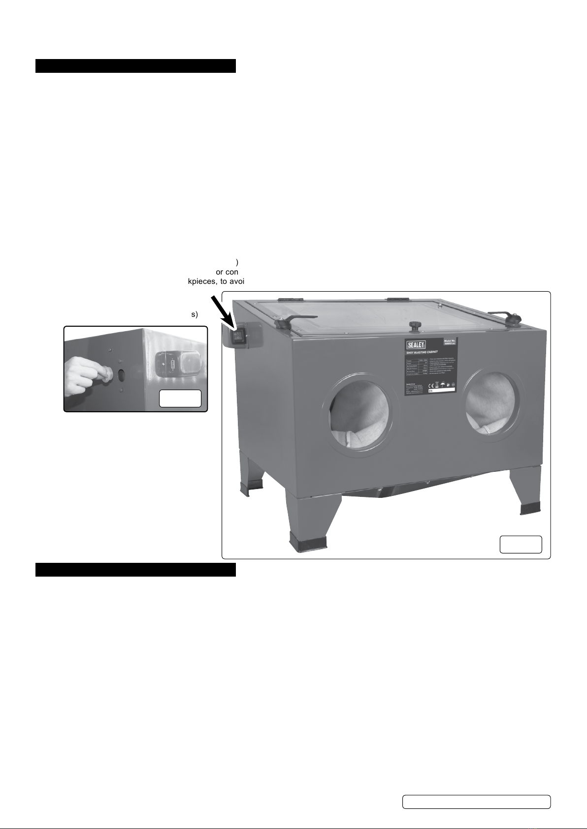
SHOT BLAST CABINET WITH GUN
640mm x 490mm x 490mm
MODEL NO: SB951.V5
Thank you for purchasing a Sealey product. Manufactured to a high standard, this product will, if used according to these
instructions, and properly maintained, give you years of trouble free performance.
IMPORTANT: PLEASE READ THESE INSTRUCTIONS CAREFULLY. NOTE THE SAFE OPERATIONAL REQUIREMENTS, WARNINGS & CAUTIONS. USE
THE PRODUCT CORRECTLY AND WITH CARE FOR THE PURPOSE FOR WHICH IT IS INTENDED. FAILURE TO DO SO MAY CAUSE DAMAGE AND/OR
PERSONAL INJURY AND WILL INVALIDATE THE WARRANTY. KEEP THESE INSTRUCTIONS SAFE FOR FUTURE USE.
1. SAFETY
1.1. ELECTRICAL SAFETY
WARNING! It is the user’s responsibility to check the following:
Check all electrical equipment and appliances to ensure that they are safe before using. Inspect power supply leads, plugs and
all electrical connections for wear and damage. Sealey recommend that an RCD (Residual Current Device) is used with all electrical
products. You may obtain an RCD by contacting your local Sealey dealer.
If the product is used in the course of business duties, it must be maintained in a safe condition and routinely PAT (Portable
Appliance Test) tested.
Electrical safety information, it is important that the following information is read and understood.
1.1.1. Ensure that the insulation on all cables and on the appliance is safe before connecting it to the power supply.
1.1.2. Regularly inspect power supply cables and plugs for wear or damage and check all connections to ensure that they are secure.
1.1.3. Important: Ensure that the voltage rating on the appliance suits the power supply to be used and that the plug is tted with the
correct fuse - see fuse rating in these instructions.
8DO NOT pull or carry the appliance by the power cable.
8DO NOT pull the plug from the socket by the cable. Remove the plug from the socket by maintaining a rm grip on the plug.
8DO NOT use worn or damaged cables, plugs or connectors. Ensure that any faulty item is repaired or replaced immediately by a
qualied electrician.
1.1.4. This product is tted with a BS1363/A 13 Amp 3 pin plug.
If the cable or plug is damaged during use, switch the electricity supply and remove from use.
Replace a damaged plug with a BS1363/A 13 Amp 3 pin plug. If in doubt contact a qualied electrician.
Class II products are wired with live (brown) and neutral (blue) only are marked with the
Class II symbol;
A) Connect the BROWN live wire to the live terminal ‘L’.
B) Connect the BLUE neutral wire to the neutral terminal ‘N’.
C) After wiring, check that there are no bare wires and ensure that all wires have been correctly
connected.
Ensure that the cable outer sheath extends inside the cable restraint and that the restraint is tight.
8DO NOT connect either wire to the earth terminal.
Sealey recommend that repairs are carried out by a qualied electrician.
1.2. REGARDING DIRECT MAINS POWER USE WITH THE TRANSFORMER PLUG.
You must also read and understand the following instructions concerning electrical safety.
1.2.1. The Electricity At Work Act 1989 requires all portable electrical appliances, if used on business premises, to be tested a
qualified electrician, using a Portable Appliance Tester (PAT), at least once a year.
1.2.2. The Health & Safety at Work Act 1974 makes owners of electrical appliances responsible for the safe condition of the appliance
and the safety of the appliance operator. If in any doubt about electrical safety, contact a qualied electrician.
1.2.3. You must ensure that you:
9Inspect the transformer plug, cable, and plug for wear and damage to ensure items are safe before connecting to the mains power
supply. If worn or damaged DO NOT use and immediately replace, or contact a qualified electrician.
9Check cables are always protected against short circuit and overload.
IMPORTANT: Check that the voltage marked on the transformer plug is the same as the power supply to be used.
9 Uncoil the lead from the transformer before use.
8DO NOT attempt to pull the transformer plug from the mains socket by the lead.
8DO NOT use any other type of transformer with the cabinet.
8DO NOT try to open or dismantle the transformer plug or charging base.
8DO NOT use the transformer plug to power any other electrical item.
8DO NOT get the transformer wet, or use in wet, damp conditions (for indoor use only).
WARNING! NEVER substitute a standard 13 amp 3 pin plug, or any other type of plug, for the transformer plug .
1.3. GENERAL SAFETY
WARNING! Ensure Health & Safety, government and local authority regulations relating to the use of shot blasting are adhered to
when using this equipment. Familiarise yourself with the applications, limitations and potential hazards peculiar to the cabinet.
WARNING! Disconnect the cabinet from the mains power and the air supply before attempting to change accessories or carry out
any servicing or maintenance.
Recommended fuse rating
3 Amp
SB951.V5 Issue 3 (HF) 25/10/18
Original Language Version
© Jack Sealey Limited
Refer to
instructions
Wear eye
protection
Wear protective
clothing
Keep away from
rain

9Maintain the cabinet in good condition Replace or repair damaged parts. Use genuine parts only. Unauthorised parts may be
dangerous and will invalidate the warranty.
9Locate cabinet in a suitable work area and keep area clean, tidy and free from unrelated materials. Ensure there is adequate lighting.
9Use only dry abrasives such as proprietary brands of glass beads, silicon carbide, aluminium oxide and silica sand. We recommend
Sealey item B5KG. Never use fluids or mix fluids with another media in the unit.
WARNING! Always wear coveralls, approved eye or face and when operating the cabinet.
9Keep the unit lid closed and secured when in use.
WARNING! Ensure correct air pressure is maintained and not exceeded. (Max 90psi).
9Always keep the blast nozzle directed at the workpiece. Never use outside the unit and always use with the lid closed.
9Regularly check that the exhaust vent at the back of the cabinet is clear and not blocked and that there is space between it and any
wall.
9Ensure the floor is clean and free from blasting media spillage; use a type “H” vacuum cleaner with a hepa filter.
9Keep children and non-essential persons away from the work area.
9 When not in use disconnect from the electrical mains and the air supply.
8DO NOT clean up media spillage with a brush or compressed air.
8DO NOT use the cabinet for a task it is not designed to perform.
8DO NOT operate the cabinet if any parts are damaged or missing as this may cause failure and/or personal injury.
8DO NOT operate the cabinet with the lid open.
8DO NOT stand on the cabinet.
8DO NOT get the cabinet wet or use in damp or wet locations or areas where there is condensation.
8DO NOT operate the cabinet when you are tired or under the influence of alcohol, drugs or intoxicating medication.
8DO NOT leave the cabinet operating unattended.
2. INTRODUCTION
Steel cabinet with replaceable viewing screen and internal illumination. Fitted with shot blasting gun and suitable for proprietary brands of glass
beads, silicon carbide, aluminium oxide and silica sand only. Excellent for a wide variety of workshop and bodyshop cleaning applications.
Requires a standard, dry workshop air supply. Supplied assembled and ready for use.
3. SPECIFICATION
Model No: ................................................................... SB951
Air Consumption: ......................................................... 12cfm
Door Size: .........................................................530 x 440mm
Doors: ..................................................................................1
Inlet Size: ..................................................................1/4”BSP
Nett Weight: ..............................................................15.99Kg
Operating Pressure:...................................................... 90psi
Overall Dimensions (W x D x H):.............640 x 490 x 490mm
Viewing Area: ....................................................490 x 395mm
4. ASSEMBLY
4.1. AIR SUPPLY FIG.1
4.1.1. You will require an air pressure of 60-90psi, and an air volume of 12cfm to operate the unit efficiently.
WARNING! Ensure air supply is clean, dry and does not exceed 90psi. Too high an air pressure and/or unclean or damp air will
shorten the product life due to excessive wear and may be dangerous, causing possible damage and/or personal injury.
4.1.2. Drain the air supply tank daily. Clean compressor air inlet filter weekly. For recommended hook-up see diagram below.
4.1.3. Line pressure should be increased to compensate for unusually long air hoses (over 8 metres).The minimum hose and fittings
bore should be 10mm.
4.1.4. Keep hoses away from heat, oil and sharp edges. Check hoses for wear and poor connections.
4.1.5. Cabinet input connection is 1/4”BSP.
4.2. ASSEMBLY
4.2.1. Unpack the product and check contents. Should there be any damaged or missing parts contact your supplier immediately.
4.2.2. Push plastic suction hose (14) onto small diameter end of steel suction tube (15). Fit suction tube (15) under clips in base of cabinet.
4.2.3. Remove fitting (18) and one steel washer (17) from air hose connector (16), leaving on one steel washer (17) and rubber washer.
Put connector (16) through hole in side of cabinet and secure with washer (17) and fitting (18).
g.1
Recommended hook up diagram
Note: Numbers in brackets refer to item numbers shown in the associated Parts List.
SB951.V5 Issue 3 (HF) 25/10/18
Original Language Version
© Jack Sealey Limited

4.2.4. Remove blanking plug from rear panel arrow “A” Fig.2.
4.2.5. Fit screen (23) into cabinet with angled corner to rear right hand side, to allow suction hose (14) through.
5. OPERATION
WARNING! Ensure you read, understand and apply safety instructions in Section 1 before using the unit.
NOTE! We strongly recommend that a suitable dust extraction system is used with this unit.
If dust extraction is not used, media may be forced out of the joints as pressure builds up. You can alleviate this to some
extent by removing the white blanking plug (Fig.2) situated on the upper left corner at the rear of the tank when viewed
from the front. This however, will not substitute for a suitable dust extraction system.
5.1. Connect the air supply to the inlet on the side of the cabinet. Ensure the gun valve is in the “o” position before connecting the air
supply.
5.2. Check all fittings to ensure there are no air leaks.
5.3. Pour the abrasive media into the centre of the cabinet. DO NOT use more than 10lbs (4.5kg). Excessive amounts of abrasive will
impair visibility, create poor blasting performance and could block the air exhaust.
5.4. The unit is supplied with four ceramic nozzles being 4, 5, 6, & 7mm hole diameter respectively. The choice of nozzle depends on the
size of the blasting media. Coarse media should be used with the larger nozzles, fine media should be used with the smaller
nozzles. To fit a new nozzle, unscrew the nozzle retaining ring, remove the existing nozzle and replace with the new one.
5.5. Plug the transformer into mains socket and transformer lead plug into light switch box and the unit is ready for use.
5.6. Place the workpiece in the cabinet and close and latch the lid securely.
WARNING! Failure to securely close the lid could result in damage and/or personal injury.
5.7. Turn on light and air supply and insert hands into cabinet gloves. Grasp gun and depress the trigger to start the blasting process.
5.8. Move the blast media (which looks like steam) continuously over the workpiece in an even and circular motion. To avoid undesirable
peening the flow should not be too hard or concentrated. The surface finish may vary from coarse to fine depending on the size of the
abrasive media. On delicate workpieces, to avoid unnecessary peening or excessive abrasion, begin the blasting with a low airflow.
6. MAINTENANCE
WARNING! Ensure the cabinet is disconnected from the electrical mains and the air supply before attempting any
maintenance.
6.1. Ensure the blasting media does not become damp. Keep the air supply dry at all times. Dispose of any damp media.
6.2. Replace media when it has become excessively dusty, loses its granular or spherical appearance, or is significantly contaminated
with debris from workpieces. This is usually noticed when media from the nozzle looks like a smoke cloud rather than steam.
6.3. Regularly check that the exhaust vents at the side and rear of the cabinet are clear.
6.4. Regularly check gun blast nozzle to ensure it does not become blocked with media. Immediately replace worn or damaged nozzle.
6.5. If abrasive pick-up hose becomes blocked, cover the gun tip to force air back through the hose. Ensure the lid is correctly closed.
6.6. Replace the transparent protective sheet on the underside of the Perspex window when visibility becomes reduced.
Part view on arrow "A"
showing white blanking plug.
(See note in Operating Instructions)
g.2
A
g.3
SB951.V5 Issue 3 (HF) 25/10/18
Original Language Version
© Jack Sealey Limited

7. TROUBLESHOOTING
PROBLEM POSSIBLE CAUSE REMEDY
Excessive dust cloud in the cabinet. 1. Exhaust vent or air flow is blocked.
2. Abrasive is worn.
3. Too much abrasive in the cabinet
4. Loose air line or fittings.
1. Clean vent and keep vent away from any wall.
Connect to a suitable dust extraction system.
2. Replace.
3. Remove excess with a type "H" vacuum cleaner.
4. Check and tighten all air fittings.
Uneven blasting. 1. Too much abrasive in cabinet.
2. Moisture inside cabinet.
1. Remove excess with a type "H" vacuum cleaner.
2. Check air line for moisture.
Inadequate speed or efficiency of blast. 1. Abrasive is worn.
2. Pressure is too low.
1. Replace.
2. Check that there are no supply blockages or leaks.
Increase pressure. Max:90psi
Static electricity. 1. Dry weather conditions. 1. Leave the workpiece to stand for a while.
Blast pattern too wide or ineffective. 1. Nozzle blocked or worn. 1. Unblock or replace nozzle
Sealey Group, Kempson Way, Suffolk Business Park, Bury St Edmunds, Suffolk. IP32 7AR
01284 757500 01284 703534 sales@sealey.co.uk www.sealey.co.uk
ENVIRONMENT PROTECTION
Recycle unwanted materials instead of disposing of them as waste. All tools, accessories and packaging should be sorted, taken to
a recycling centre and disposed of in a manner which is compatible with the environment. When the product becomes completely
unserviceable and requires disposal, drain any fluids (if applicable) into approved containers and dispose of the product and fluids
according to local regulations.
WEEE REGULATIONS
Dispose of this product at the end of its working life in compliance with the EU Directive on Waste Electrical and Electronic Equipment
(WEEE). When the product is no longer required, it must be disposed of in an environmentally protective way. Contact your local solid
waste authority for recycling information.
Note: It is our policy to continually improve products and as such we reserve the right to alter data, specifications and component parts without prior
notice.
Important: No Liability is accepted for incorrect use of this product.
Warranty: Guarantee is 12 months from purchase date, proof of which is required for any claim.
SB951.V5 Issue 3 (HF) 25/10/18
Original Language Version
© Jack Sealey Limited

EC DECLARATION
OF CONFORMITY
Description and Function:������������������������������������������������������������������������������������������������������������������������������������������������������������������������
Model/Type:���������������������������������������������������������������������������������������������������������������������������������������������������������������������������������������������
Manufacturing Date/Serial Number where applicable: ����������������������������������������������������������������������������������������������������������������������������
This declaration of conformity is issued under the sole responsibility of the manufacturer:
Jack Sealey Ltd, Kempson Way, Suffolk Business Park, Bury St Edmunds, Suffolk. IP32 7AR
Declaration of Conformity in accordance with the above Directive(s)�
Technical le compiled by: Jack Sealey Ltd
Being the responsible person appointed by the manufacturer.
Signed�������������������������������������������������������������������������������������������
Date�����������������������������������������������������������������������������������������������
Name���������������������������������������������������������������������������������������������
Position�����������������������������������������������������������������������������������������
Place: Bury St Edmunds
Shot Blast Cabinet with Gun 640 x 490 x 490mm
SB951 v5
2014/30/EU EMC Directive
2014/35/EU Low Voltage Directive
2011/65/EU RoHS Directive
References to harmonised standard(s)
EN 61000-3-2:2014 ����������������������������������������������������������������������
EN 61000-3-3:2013 ����������������������������������������������������������������������
EN 60204-1:2006+A1:2009+AC:2010������������������������������������������
������������������������������������������������������������������������������������������������������
������������������������������������������������������������������������������������������������������
������������������������������������������������������������������������������������������������������
������������������������������������������������������������������������������������������������������
������������������������������������������������������������������������������������������������������
������������������������������������������������������������������������������������������������������
������������������������������������������������������������������������������������������������������
������������������������������������������������������������������������������������������������������
������������������������������������������������������������������������������������������������������
4 July 2018
Steve Buckle�
Marketing Director�
XVII2813
Sealey Group, Kempson Way, Suffolk Business Park, Bury St Edmunds, Suffolk. IP32 7AR
01284 757500 01284 703534 sales@sealey.co.uk www.sealey.co.uk

SB951.V5 Issue 3 PL 7/12/17
Sealey Group, Kempson Way, Suffolk Business Park, Bury St Edmunds, Suffolk. IP32 7AR
01284 757500 01284 703534 sales@sealey.co.uk www.sealey.co.uk
Page 1 of 1
NOTE: It is our policy to continually improve products and as such we reserve the right to alter data, specifications and component parts without prior notice.
IMPORTANT: No liability is accepted for incorrect use of product.
WARRANTY: Guarantee is 12 months from purchase date, proof of which will be required for any claim.
Parts Information:
Shot Blast Cabinet with Gun 640 x 490 x
490mm
Model No: SB951.V5
Item Part No. Description
1 SB.V LID, TOP, TRANSPARENT
1.1 SB.V. CHAIN, TOP LID
1.2 SB.V. SCREW
1.3 SB.V. NUT
1.4 SB.V. HINGE
1.5 SB.V. KNOB
2 SB.V FRONT PANEL
3 SB.V REAR PANEL
4L SB.VL LEFT PANEL
4R SB.VR RIGHT PANEL
5 SB.V BASE
6 SB.V LAMP CLAMP
7A SB.VA FRONT LEG (LEFT)
7B SB.VB FRONT LEG (RIGHT)
-- MSP.S MACHINE SCREW PAN HEAD PHILLIPS
M4x16mm
9 MSP.S MACHINE SCREW PAN HEAD PHILLIPS
M6x12mm
9.1 SN.S STEEL NUT M4 ZINC DIN934 (SINGLE)
10 SB.V NUT
11 SB.V SANDING GUN
12 SB.V SANDING GUN NOZZLE (PK OF 4)
Item Part No. Description
13 SB.V AIR HOSE
14 SB.V SUCTION HOSE, PLASTIC
15 SB.V SUCTION HOSE, STEEL
16 SB.V CONNECTOR
17 SB.V WASHER
18 SB.V AIR SUPPLY FITTING
19 SB.V HOSE CLAMP 1/4"
20 SB.V GLOVE CLAMP
21 SB.V GLOVES
22 SB.V SCREW
23 SB.V SCREEN
24 SB.V FILTER
24.1 SB.V. FILT ER
25 SB.V PRESSING RING
26 SB.V WORKLIGHT
26.1 SB.V. CABLE GRIP
27 SB.V SWITCH BOX
27.1 SB.V. MAINS TRANSFORMER
-- SB.V PVC MAIN SCREEN
-- SB.V PVC WINDOW FRAME
-- SB.V PROTECTIVE SHEET
This manual suits for next models
1
Table of contents
Other Sealey Shot Blasting Machine manuals

Sealey
Sealey SB993.V2 User manual

Sealey
Sealey SB970.V4 User manual

Sealey
Sealey SB994 User manual

Sealey
Sealey PSB10 User manual

Sealey
Sealey SB951/C User manual

Sealey
Sealey SB972.V3 User manual

Sealey
Sealey SG10.V2 User manual

Sealey
Sealey Power PRODUCTS SB970.V3 User manual

Sealey
Sealey SB993 User manual

Sealey
Sealey SB993.V2 User manual