Sealey ST80 User manual

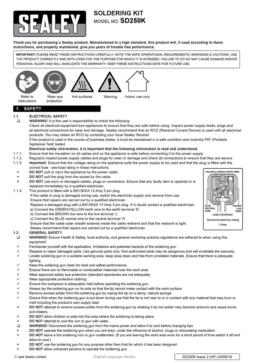
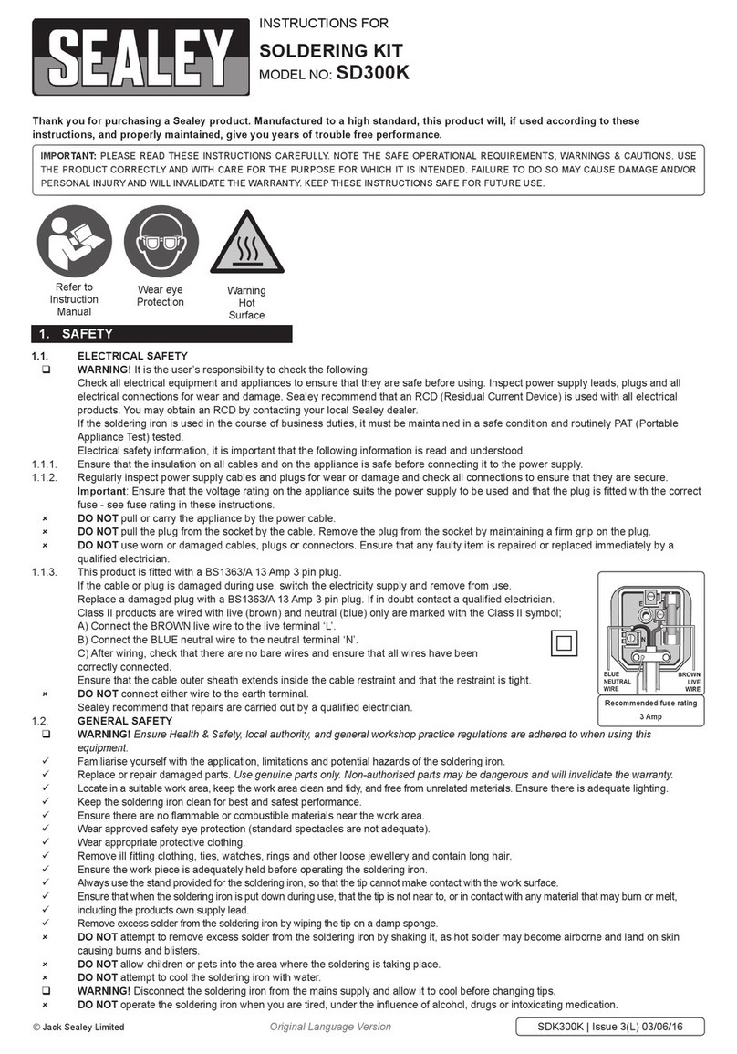
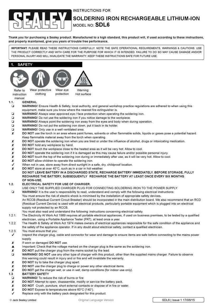
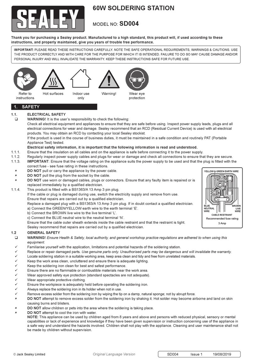
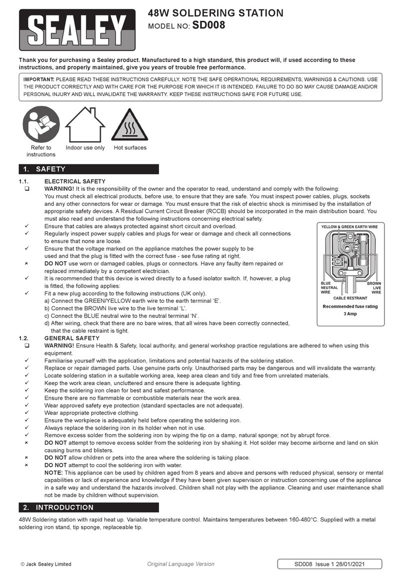
1.1. ELECTRICAL SAFETY
WARNING! It is the responsibility of the owner and the operator to read, understand and comply with the following:
You must check all electrical products, before use, to ensure that they are safe. You must inspect power cables, plugs, sockets and any other
connectors for wear or damage. You must ensure that the risk of electric shock is minimised by the installation of appropriate safety devices. A
Residual Current Circuit Breaker (RCCB) should be incorporated in the main distribution board. We also recommend that a Residual Current
Device (RCD) is used. It is particularly important to use an RCD with portable products that are plugged into a supply which is not protected by
an RCCB. If in any doubt consult a qualified electrician. You may obtain a Residual Current Device by contacting your Sealey dealer.
You must also read and understand the following instructions concerning electrical safety.
1.1.1. The Electricity at Work Act 1989 requires that all portable electrical appliances, if used on business premises, are tested by a
qualified electrician, using a Portable Appliance Tester (PAT), at least once a year.
1.1.2. The Health & Safety at Work Act 1974 makes owners of electrical appliances responsible for the safe condition of those appliances
and the safety of the appliance operators. If in any doubt about electrical safety, contact a qualified electrician.
1.1.3. Ensure that the insulation on all cables and on the appliance is safe before connecting it to the power supply. See 1.1.1. and 1.1.2.
and use a Portable Appliance Tester.
1.1.4. Ensure that cables are always protected against short circuit and overload.
1.1.5. Regularly inspect power supply cables and plugs for wear or damage and check all
connections to ensure that none is loose.
1.1.6. Important: Ensure that the voltage marked on the appliance matches the power supply
to be used and that the plug is fitted with the correct fuse - see fuse rating at right.
1.1.7. DO NOT pull or carry the appliance by the power cable.
1.1.8. DO NOT pull the plug from the socket by the cable.
1.1.9. DO NOT use worn or damaged cables, plugs or connectors. Have any faulty item repaired or
replaced immediately by a qualified electrician. When a BS 1363/A UK 3 pin plug is damaged, cut
the cable just above the plug and dispose of the plug safely.
Fit a new plug according to the following instructions (UK only).
a)Connect the GREEN/YELLOW earth wire to the earth terminal ‘E’.
b)Connect the BROWN live wire to the live terminal ‘L’.
c)Connect the BLUE neutral wire to the neutral terminal ‘N’.
d)After wiring, check that there are no bare wires, that all wires have been connected
correctly, that the cable outer insulation extends beyond the cable restraint and that the
restraint is tight.
Double insulated products, which are always marked with this symbol , are fitted with live (brown)
and neutral (blue) wires only.
To rewire, connect the wires as indicated above - DO NOT connect either wire to the earth terminal.
1.1.10. Products which require more than 13amps are supplied without a plug. In this case you must contact a qualified electrician to ensure
that a suitably rated supply is available. We recommend that you discuss the installation of an industrial round pin plug and
socket with your electrician.
1.1.11. If an extension reel is used it should be fully unwound before connection. A reel with an RCD fitted is preferred since any appliance
plugged into it will be protected. The cable core section is important and should be at least 1.5mm², but to be absolutely sure that the
capacity of the reel is suitable for this product and for others which may be used in the other output sockets, we recommend the use
of 2.5mm² section cable. If an extension reel is to be used outdoors, ensure it is marked for outdoor use.
1.2 GENERAL SAFETY
WARNING! Ensure Health & Safety, local authority, and general workshop practice regulations are adhered to when using this
equipment.
Familiarise yourself with the application , limitations and potential hazards of the soldering station.
Replace or repair damaged parts. Use genuine parts only. Unauthorised parts may be dangerous and will invalidate the warranty.
Locate soldering station in a suitable working area, keep area clean and tidy and free from unrelated materials.
Keep the work area clean, uncluttered and ensure there is adequate lighting.
Keep the soldering iron clean for best and safest performance.
Ensure there are no flammable or combustible materials near the work area.
Wear approved safety eye protection (standard spectacles are not adequate).
Wear appropriate protective clothing.
Ensure the workpiece is adequately held before operating the soldering iron.
Always replace the soldering iron in its holder when not in use.
INSTRUCTIONS FOR:
SOLDERING STATION 80w
MODEL NO: ST80
IMPORTANT: PLEASE READ THESE INSTRUCTIONS CAREFULLY. NOTE THE SAFE OPERATIONAL REQUIREMENTS, WARNINGS & CAUTIONS. USE THE PRODUCT
CORRECTLY AND WITH CARE FOR THE PURPOSE FOR WHICH IT IS INTENDED. FAILURE TO DO SO MAY CAUSE DAMAGE AND/OR PERSONAL INJURY AND WILL
INVALIDATE THE WARRANTY. KEEP THESE INSTRUCTIONS SAFE FOR FUTURE USE.
Thank you for purchasing a Sealey product. Manufactured to a high standard, this product will, if used according to these instructions
and maintained properly, give you years of trouble free performance.
REFER TO
INSTRUCTIONS
GENERAL
WARNING
INDOOR USE
ONLY
HOT SURFACE
RECOMMENDED
FUSE RATING: 3AMP
1. SAFETY
ST80 Issue:1 31/03/15
© Jack Sealey Limited Original Language Version

Remove excess solder from the soldering iron by wiping the tip on a damp, natural sponge; not by abrupt force.
DO NOT attempt to remove excess solder from the soldering iron by shaking it. Hot solder may become airborne and land on skin causing
burns and blisters.
DO NOT allow children or pets into the area where the soldering is taking place.
DO NOT attempt to cool the gun with water.
2. INTRODUCTION
80W Soldering Station with large LCD display and backlight. Three adjustable heat settings with ± 10°C accuracy as well as manual temperature
selection. Features auto-standby and shutdown, settable between 1-120 minutes to ensure reduced energy consumption. Takes just 10 seconds to
heat from 0-350°C. ESD Safe. Supplied with soldering sponge and aluminium soldering iron stand.
3. SPECIFICATION
Model No: ...................................................................ST80
Supply/Power: ............................................................230V/80W
Frequency:...................................................................50Hz
Heating Element Voltage: ..................................................... 28V AC
Temperature Stability: ...........................................±2°C (in still air, no load)
Temperature Accuracy: ........................................................ ±10°C
Maximum Temperature range:.......................................150-480°C/302-896°F
Tip-to-Ground resistance: ........................................................<2Ω
Tip-to-Ground Voltage: .........................................................<2mV
4. OPERATION
1 . . . . . . . . . . Set Temperature Mode
2 . . . . .Real-Time Temperature Mode
3 . . . . . . . . . . . . . . . Calibration Mode
4 . . . . Temperature Stored: Channel1
5 . . . . Temperature Stored: Channel2
6 . . . . Temperature Stored: Channel3
7 . . . . . . . . Analogue Current Display
8 . . . . . . . . . . . . . . Fahrenheit Values
9 . . . . . . . . . . . . . . . . .Celsius Values
10 . . . . . .Real-Time Tip Temperature
fig.1
fig.2
ST80 Issue:1 31/03/15
© Jack Sealey Limited Original Language Version
NOTE: This appliance can be used by children aged from 8 years and above and persons with reduced physical, sensory or mental capabilities or
lack of experience and knowledge if they have been given supervision or instruction concerning use of the appliance in a safe way and understand
the hazards involved. Children shall not play with the appliance. Cleaning and user maintenance shall not be made by children without supervision.

NOTE: Dampen the sponge wiper before using the soldering station.
4.1. Connection
4.1.1. Push the DIN plug attached to the iron lead into the socket on the front panel of the control unit (fig.1).
4.1.2. Push the power cord into the socket at the rear of the control unit, after ensuring that the power supply is to the correct standard.
4.2. Switching On
4.2.1. Switch the on/off switch to the ‘.’ setting.
4.2.2. The display will show ‘80’ briefly, denoting the model number.
4.2.3. The last temperature set will be displayed for 3 seconds.
4.2.4. After a further 3 seconds, the display will show the real-time temperature of the tip.
NOTE: The number of bars shown by the analogue current display (fig.1.7) represent the current being applied to the tip.
4.3. Temperature Setting
4.3.1. The default temperatures stored by buttons: 1, 2 and 3 are 200,300 and 400°C respectively.
4.3.2. Withthenormalsettingsapplied,thetemperaturecanbeadjustedbymeansofthe▲and▼buttons(fig.1).
4.3.3. The display will go to ‘set’ and the required temperature will either increase or decrease. Holding the button down will allow rapid
adjustment.
4.3.4. When the button is released, the display will revert to ‘real’ to illustrate the current temperature.
4.3.5. To store a required temperature, set as in 4.3.1., then hold one of the the preset buttons down for 3 seconds. The new temperature will
then become the stored value assigned to that button.
4.3.6. The default temperature setting is in 5°C graduations. For finer adjustment see section 4.7.
4.4. Locking the Keypad
4.4.1 The keypad may be locked by pressing all three preset buttons simultaneously for 3 seconds.
4.4.2. The display will show ‘loc’ (fig.3) and none of the buttons will function.
4.4.3. To unlock the keypad, press all three keys again for 3 seconds; the display and button functions will revert to normal.
4.5. System Setting
4.5.1. Toaccessthesystemsettingpages,press▲and▼buttonssimultaneouslyfor3seconds.Thiswilldisplaypage1ofthesystemsmenu
(fig.4).
4.5.2. Toscrollbetweensystemsettingpages,usethe▲and▼buttons.Eachclickofthe▼buttonadvancesbyonepage,andviceversa.
fig.3
page 1 page 2 page 3
fig.4
4.6. Calibration
4.6.1. Toaccessthesystemsettingpages,press▲and▼buttonssimultaneouslyfor3seconds.
4.6.2. To start calibration: press ‘1’ on page1. ‘CAL’ will flash.
4.6.3. Ensure that the tip of the soldering iron is well tinned with solder to disperse the heat.
4.6.4. Measure the tip temperature (T1) and compare with the reading (T2).
4.6.5. IfT1exceedsT2,press▲untilthedifferenceisdisplayed.IfT2exceedsT1,press▼untilthedifferenceisdisplayed.
E.G: Ifmeasuredtemperature(T1)is350°,anddisplay(T2)shows370°,thedisplaywillneedreducingby20°.Scrollwillthe▼button
until -20° is reached.
4.6.6. Press button ‘1’ to save the setting.
4.7. Fine Temperature Adjustment
4.7.1. Toaccessthesystemsettingpages,press▲and▼buttonssimultaneouslyfor3seconds.
4.7.2. Toaccessthesystemsettingpages,press▲and▼buttonssimultaneouslyfor3seconds.
4.7.3. To alter the temperature adjustment between 5° and 1° increments: press ‘2’ on page1. ‘Fin’ will flash.
4.7.4. Scrollbetween‘Off’(5°)and‘On’(1°)bymeansofthe▲and▼buttons.
4.7.5. Press button ‘2’ to save the setting.
4.8. Temperature Scale Selection
4.8.1. Toaccessthesystemsettingpages,press▲and▼buttonssimultaneouslyfor3seconds.
4.8.2. To switch between Celsius and Fahrenheit scales: press ‘3’ on page 1.’C-F’ will flash.
4.8.3. Toggleeitherthe▲and▼buttontochangefromCtoFandback.
4.8.4. Press button ‘3’ to save the change.
ST80 Issue:1 31/03/15
© Jack Sealey Limited Original Language Version
Page Functions

4.9. Stand-by Mode
4.9.1. Toaccessthesystemsettingpages,press▲and▼buttonssimultaneouslyfor3seconds.
4.9.2. In stand-by mode the iron will, if not touched during the selected time, cool down to 150° C and remain at that temperature until the iron is
next removed from the rest or any control pressed. At this point it will re-establish the set temperature.
4.9.3. Tosetthestand-bytime:selectpage2bypressingthe▼buttonandthenpress‘1’.‘Stb’willflash.
4.9.4. Thedefaultsettingis‘OFF’.Toselectastand-bytime:pressthe▲keytoincreasetheperiod(keepingthebuttonpressedallowsthetime
to increase rapidly).
4.9.5. Usethe▲and▼buttontoalterthesettimeorthe▼buttontoscrolldownto‘OFF’.
4.9.6. Press button ‘1’ to store the setting.
4.10. Automatic Shutdown Mode.
NOTE: automatic shutdown can only be selected if the stand-by time (section 4.9.) has been set. The shutdown time must be greater
than the stand-by time.
4.10.1. Toaccessthesystemsettingpages,press▲and▼buttonssimultaneouslyfor3seconds.
4.10.2. Tosettheautomaticshutdowntime:selectpage2bypressingthe▼buttonandthenpress‘2’.‘SdΠ’willflash.
4.10.3. Thedefaultsettingis‘OFF’.Toselectaashutdowntime:pressthe▲keytoincreasetheperiod.Keepingthebuttonpressedallowsthe
time to increase rapidly.
4.10.4. Press ‘2’ to save the setting.
4.10.5. To reactivate from shutdown mode: switch the soldering station off and restart.
NOTE: When in shutdown mode, a small amount of current is still being consumed. If not being used, switch off and isolate from the
power supply to ensure absolute safety.
4.11. Touch tone
4.11.1. Toaccessthesystemsettingpages,press▲and▼buttonssimultaneouslyfor3seconds.
4.11.2.Todisableorenabletheaudibletouchtone:selectpage2bypressingthe▼buttonandthenpress‘3’.‘bL’willflash.
4.11.3. Toggleeitherthe▲or▼buttontoswitchthetoneonoroff.
4.11.4. Press ‘3’ to save the setting.
4.12. Factory Settings
4.12.1. Toaccessthesystemsettingpages,press▲and▼buttonssimultaneouslyfor3seconds.
4.12.2. Tocancelanymanualsettingsandreturntothefactorysettings:selectpage3bypressingthe▼buttontwiceandpressingthe‘1’button.
‘FAC’ will flash.
4.12.3. Toggleeitherthe▲or▼buttontoselectfactorysettingsornot.
4.12.4. Press ‘1’ to apply.
NOTE: Once the settings have been reset, adjustments can again be made. To retain factory settings, lock the keypad as in section 4.4.
4.13. Escape
4.13.1 Toaccessthesystemsettingpages,press▲and▼buttonssimultaneouslyfor3seconds.
4.13.2. Toexitthesystemsettingpages:selectpage3bypressingthe▼buttontwice.Pressingthe‘2’(ESC)buttonwillreturnthedisplaytothe
main functions.
NOTE: the display will return to the main functions automatically after 10 seconds if no key is pressed.
DO NOT open the casing; there are no user-servicable parts inside. In case of malfunction, return to your Sealey dealer or Service
Agent.
5.1. Cleaning
DO NOT shock the iron tip to remove excess solder; use the dampened sponge wiper.
Clean the casing with a moist, soapy cloth, having ensured that the unit is isolated from the electrical supply.
5.2. Fault Codes
Fault Code/Fault Description Cause/Remedy
E-0: Abnormal Heating Alarm Transformer damaged. Power chip damaged. Short circuit in soldering iron lead
E-1: Abnormal Heating Alarm Open circuit in heating element. Heating element wiring fault.
E-2: Open Circuit Alarm Heating element damaged. Heating element wiring damaged
Poor Connections Check DIN plug and socket. Check fuse (replace if necessary with fuse of same specification)
Temperature Display Incorrect Check soldering iron for damage. Recalibrate (see section 4.6.)
Illegible code Switch off and restart.
`
5. MAINTENANCE
Environmental Protection
Recycle unwanted materials instead of disposing of them as waste. All tools, accessories and packaging should be
sorted, taken to a recycling centre and disposed of in a manner which is compatible with the environment.
When the product becomes completely unserviceable and requires disposal, dispose of it according to local regulations.
WEEE Regulations
Dispose of this product at the end of its working life in compliance with the EU Directive on Waste Electrical and
Electronic Equipment (WEEE). When the product is no longer required, it must be disposedof in an environmentally
protective way. Contact your local solid waste authority for recycling information.
NOTE: It is our policy to continually improve products and as such we reserve the right to alter data, specifications and component parts without prior notice.
IMPORTANT: No liability is accepted for incorrect use of this product.
WARRANTY: Guarantee is 12 months from purchase date, proof of which will be required for any claim.
01284 757500
01284 703534
sales@sealey.co.uk
Sole UK Distributor, Sealey Group,
Kempson Way, Suffolk Business Park,
Bury St. Edmunds, Suffolk,
IP32 7AR
www.sealey.co.uk
ST80 Issue:1 31/03/15
© Jack Sealey Limited Original Language Version
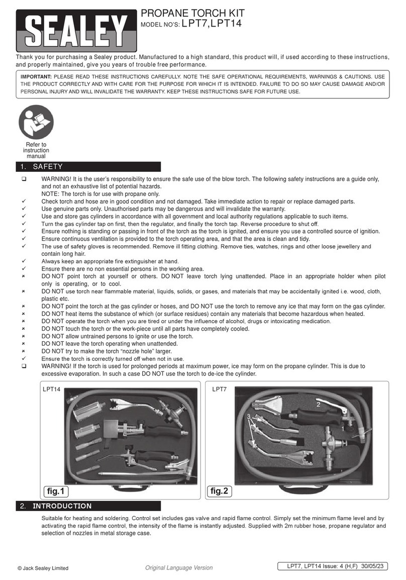
Table of contents
Other Sealey Soldering Gun manuals

Sealey
Sealey SD004 User manual

Sealey
Sealey AK2933 User manual

Sealey
Sealey SD003 User manual

Sealey
Sealey SD006 User manual

Sealey
Sealey SDL6 User manual

Sealey
Sealey SD005 User manual

Sealey
Sealey LPT7 User manual

Sealey
Sealey SD300K User manual

Sealey
Sealey SD200 User manual

Sealey
Sealey SD250K User manual
Popular Soldering Gun manuals by other brands

Weller
Weller WT 1011H Translation of the original instructions

Fervi
Fervi 443 Operation and maintenance manual

Xytronic
Xytronic LF-1000 instruction manual

Weller
Weller KHE 81 operating instructions

EINHELL
EINHELL BT-SG 100 operating instructions

Circuit Specialists
Circuit Specialists CSI PREMIER 75W instruction manual