AB932.V4 Issue 2 (ALL) 20/07/23
Original Language Version
© Jack Sealey Limited
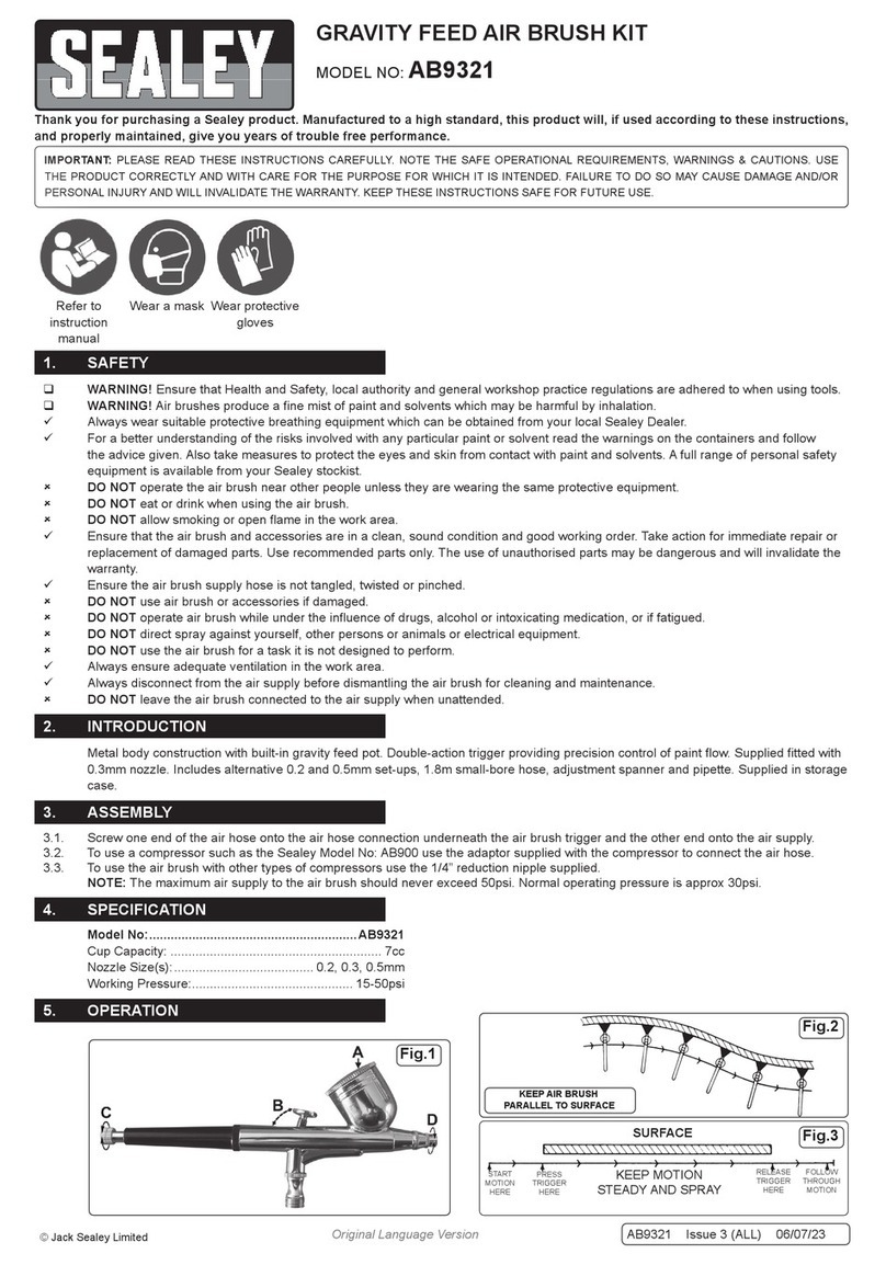
5.5. Make any necessary spray adjustments. The paint spray pattern can be adjusted by turning the xing nut (Fig.2D). The nut is fully
closed, when it has been turned clockwise to the stop point. The volume of paint dispensed can be adjusted by varying the backward
movement of the trigger (Fig.2B). This can be pre-set using the micro adjust screw (Fig.2C).
5.6. Holding the air brush about 6 inches from the surface press the trigger (Fig.2A) down. Using short strokes, move the air brush at a
steady rate, parallel to the surface, g.4.
5.7. Apply a light coat of paint, let it dry, then apply another coat. Continue with this method until the desired coverage is reached.
DO NOT spray too heavily.
NOTE: When using quick drying paints, it is advisable to clean or immerse the uid end of the air brush in a compatible solvent
between sprays.
5.8. Once you are satised with the results of your test pieces and have made any necessary adjustments to the air brush, continue with
the task to be performed. Best results are achieved with a good constant motion. Start the motion before pressing the trigger and follow
a through motion after releasing the trigger, g.5.
6. MAINTENANCE
Numbers refer to the attached parts list.
NOTE: To achieve the best results when spraying it is always best to start with the air brush clean and totally free from old paint
deposits, dirt etc. Therefore the air brush should be thoroughly cleaned immediately after each operation.
6.1. Remove the empty paint container, wipe the inside thoroughly, including the lid.
6.2. Fill the container half full of a compatible solvent and re-attach to the air brush.
6.3. Spray into a suitable container, this will clean the needle and nozzle assembly. Hold a soft cloth over the xing nut and spray again, this
will force air and the compatible solvent back through the air brush and clean the internal moving parts.
6.4. Should the air brush become clogged with paint, dismantle the air brush and clean the component parts as follows:
6.4.1. Turn off the air and disconnect the air hose from the air brush.
WARNING! The uid needle has a long sharp point and great care should be exercised when handling it.
6.4.2. Unscrew the needle cover (16) from the main body of the air brush and slide it off.
6.4.3. Unscrew the needle xing screw (15) and slide it off the needle. Carefully withdraw the needle (18) and place it somewhere safe to
avoid bending it or damaging the sharp point.
6.4.4. Unscrew the air cap (2) from the front of the air brush.
6.4.5. Loosen the air cap body (4) with the wrench provided and unscrew it. If the nozzle needs to be soaked in solvent remove the ‘O’ ring
(5) as it may be damaged by the solvent.
6.4.6. Unscrew the needle guide assembly (12, 13, 14 & 17) from the rear of the air brush body. Test the action of the sprung plunger. If this
operates smoothly no further disassembly is required.
6.4.7. The adjustment lever (10) and lever guide (11) will now be loose in the body and should be removed.
6.4.8. Any components with dried paint on them should be cleaned with a solvent suitable for the paint last used and may need to be soaked
for a while before the paint will come off. Take great care not to bend the needle when cleaning it and avoid the sharp point.
6.5. Reassemble the cleaned air brush as follows:
6.5.1. Replace ‘O’ ring (5) onto the air cap body (4) and screw nozzle into place on body (8).
8DO NOT overtighten as this may restrict the effectiveness of the spray pattern.
6.5.2. Position the adjustment lever (10) into the opening in the top of the air brush so that it sits on top of the air valve.
6.5.3. The slot in the stem of the trigger should be orientated to allow the needle to pass through it when the needle is reinserted.
6.5.4. Insert the lever guide (11) into the rear opening of the air brush body such that the convex face of the upper section rests against
the trigger.
6.5.5. Screw the needle guide assembly (12, 13, 14 & 17) into the back of the air brush until it makes contact with the lever guide (11).
Continue to screw it in until the trigger moves forwards and makes contact with the air adjustment screw (9).
6.5.6. Carefully insert the needle into the needle guide assembly and push it through until the needle tip just emerges from the air cap body
(4). Do not force it into position but allow the needle to ‘rest’ in place.
6.5.7. Slide the needle xing screw (15) over the end of the needle and screw it into the rear of the needle guide assembly.
6.5.8. Test the action of the trigger to ensure that the needle withdraws smoothly into the nozzle as the trigger is pulled back.
6.5.9. Screw the air cap (2) onto the nozzle. DO NOT do it up too tightly. Screw the needle cover (16) onto the back of the air brush body.
Fig.2
Fig.3
RELEASE
TRIGGER
HERE
FOLLOW
THROUGH
MOTION
KEEP AIR BRUSH
PARALLEL TO SURFACE
SURFACE
START
MOTION
HERE
PRESS
TRIGGER
HERE
KEEP MOTION
STEADY AND SPRAY
Fig.4 Fig.5
Fig.1
