Table of contents
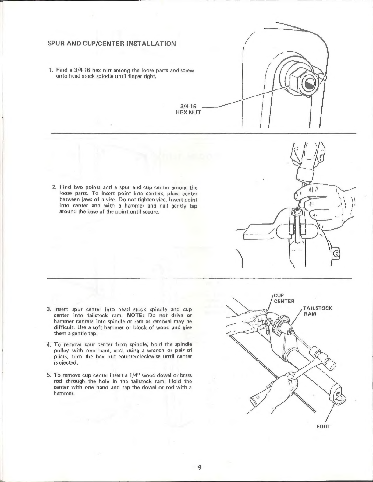
Holzmann
Holzmann VD 1100ECO user manual
Grizzly
Grizzly G0632 Parts Breakdown
Grizzly G0462 owner's manual
Grizzly G0709 owner's manual
Grizzly G0949G owner's manual
Kval
Kval 990-H Service manual
Teknatool
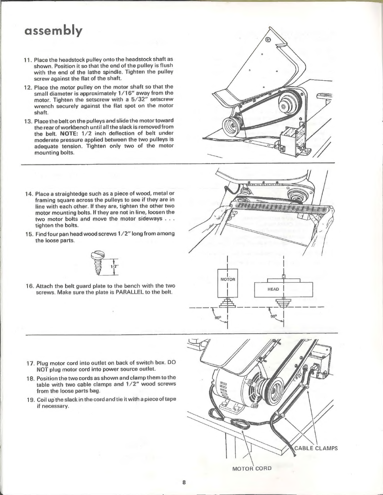
Teknatool Nova Mercury operating manual
Traub
Traub TNL12.2 operating instructions
WoodFast
WoodFast M305 instruction manual
Milltronics
Milltronics ML Series Instruction handbook
Milltronics SL6 Series Instruction handbook
OmniTurn
OmniTurn GT-75 user manual
Axminster
Axminster CQ6230A-2/910 user manual
Jet
Jet JWL-1640EVS Operating instructions and parts manual
Grizzly G4000 owner's manual
HOLZMANN MASCHINEN
HOLZMANN MASCHINEN ED1000FB user manual
Hercus
Hercus 260 Maintenance manual
Optimum
Optimum OPTIturn TM 3310 operating manual