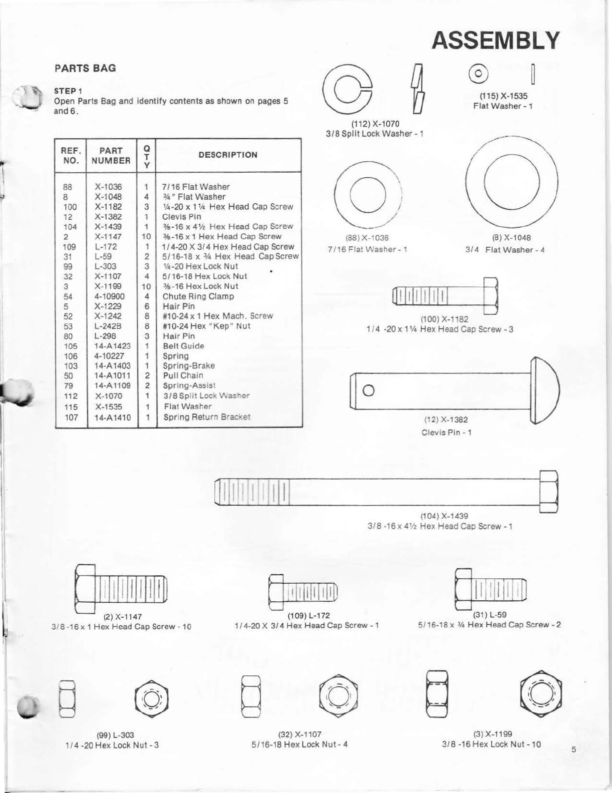
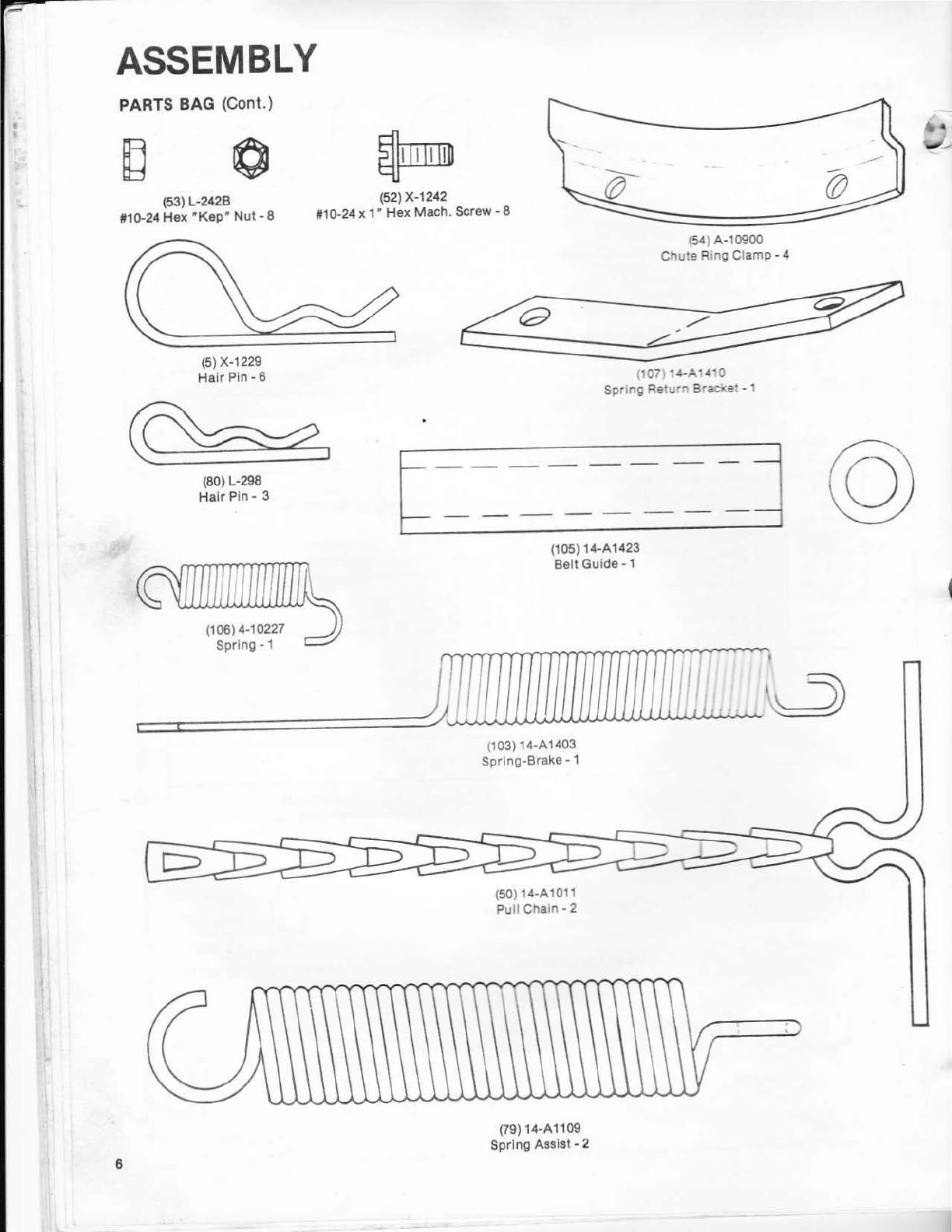
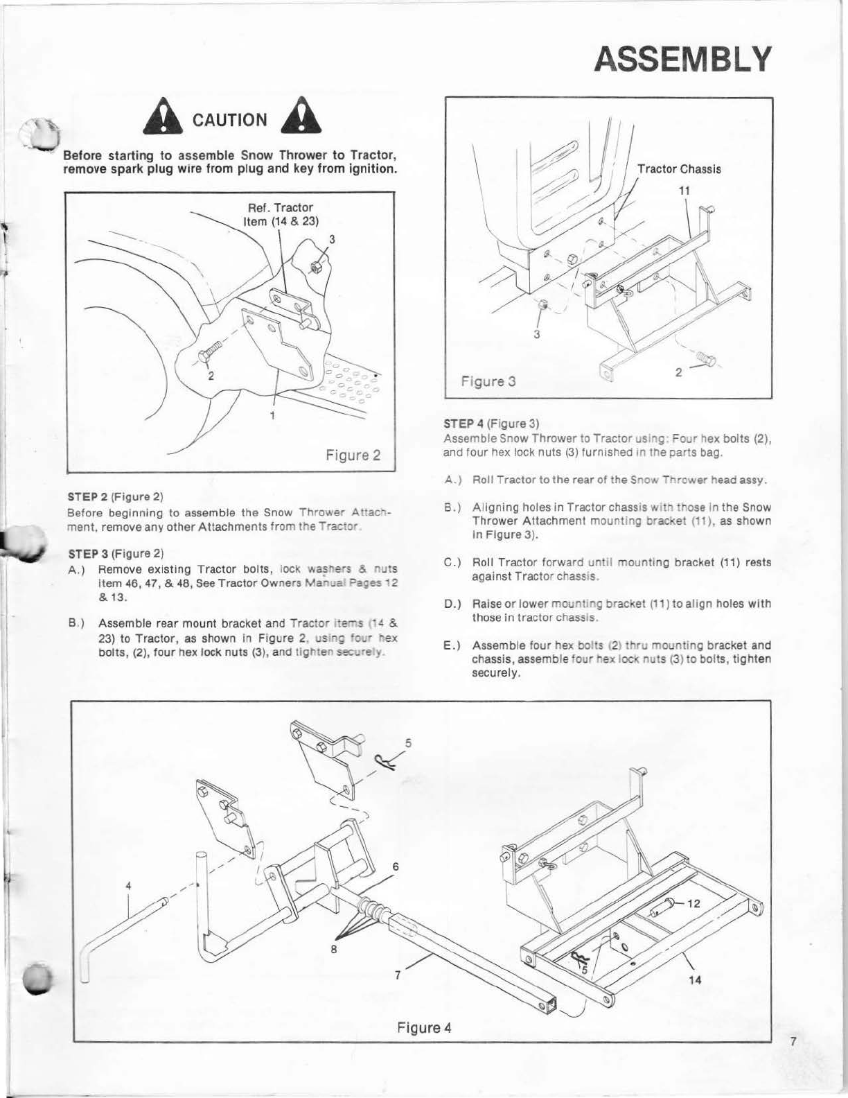
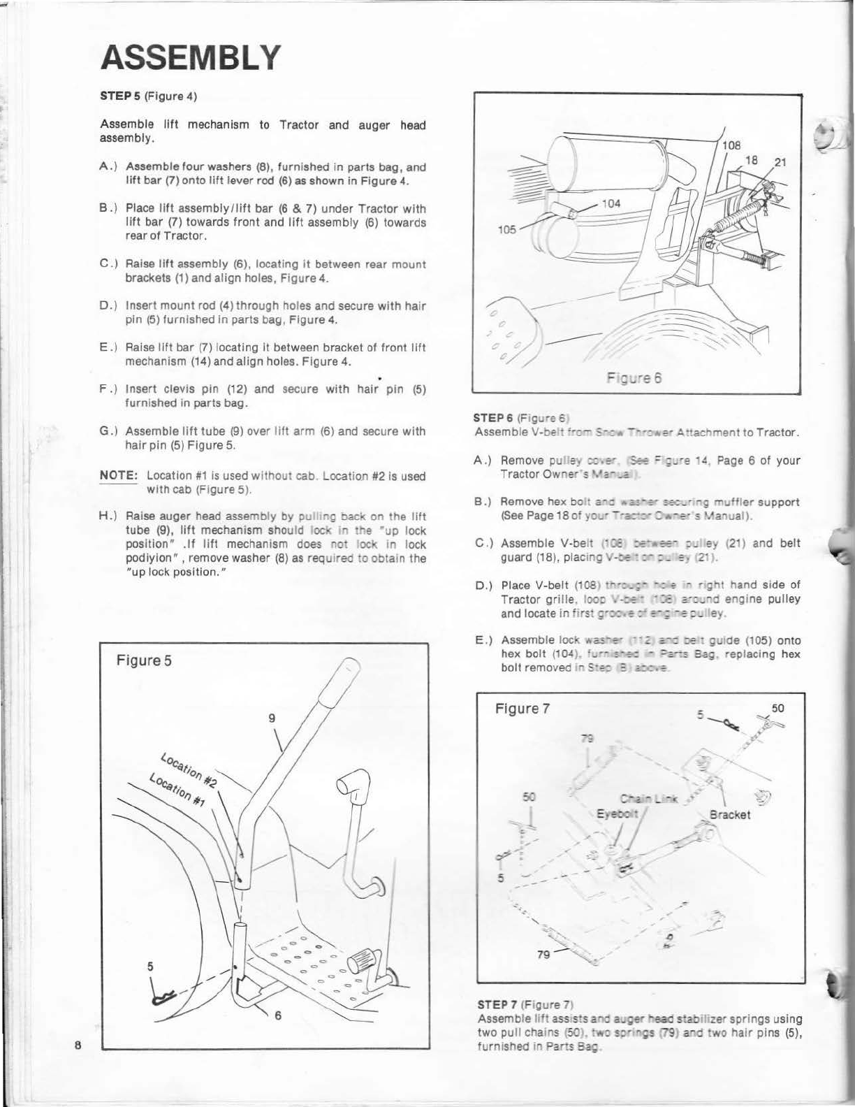
•
RULES FOR SAFE OPERATION
1.
Know
the contro
ls
and how
to
stop
quickly,
READ
THE
OWNER'S
MANUAL,
2. Do
not
allow
children to operate
the
vehicle. Do not
allow
adults to operate
without
proper Instruction.
3. Do
not
carry passengers. Keep children and pets a safe
distanceaway.
4.
Always
wear substantial footwear. Do
not
wear loose
fitting
clothing
that
could
get
caught
in
moving parts.
5. Keep
your
eyesand
mind
on
your
tractor, snow
thrower
and the area being cleaned.
Don't
let
other
interests
distract
you.
6. Do
not
attempt
to operate
your
tractor
or
mower when
not
in the
drivers
seat.
7.
Always
get
on
or
off
your
tractor
from the operators.Jeft
hand side.
8. Clear the work area of objects which
might
be picked
up
and
thrown.
9. Disengage all attachment clutches and
shift
into
neu
tra
l
before
attempting
to
start
the engine.
10.
Disengage power
to
attachments and stop the engine
before leaving
the
operator's
position.
11.
Disengage all power
to
snow
thrower
, stop the e
ngine
and disconnect spark
plug
wire
(s)
from spark p
lu
g(s)
beforecleaning making an adjustme
nt
or
repa1rs.
12. Disengage power
to
attachments when
traospon
.:-~
g
or
not in use.
Drive
slowly when
front
or
rear
rrount
ed
attachment is in transport position.
13. Take
all
possible precautions when leaving :he venicle
unattended, such
as
disengaging the power-
<aJ<e-off
lowering the attachments,
shifting
into
neutra
l.
se
ttin
g
the parking brake, stopping
the
eng
in
e, and
remov
i
ng
the key.
14.
Do
not
stop or start suddenly when going
uphill
or
downhill.
15. Reduce speed
on
slopes and make
turns
gradua
lly
to
prevent
tipping
or
loss
of
control. Exercise extreme
caution when changing
direction
on
slopes.
16. Do not
shift
gears
while
going up
or
down slopes.
Choose a gear low enough to negotiate
the
slope
without
stopping and
shifting
gears. To reduce speed,
move
throttle
lever
to
slow.
17. Stay al
er
t
for
holes in the terrain and
other
hidden
hazards.
18.
Do
not
drive
too close to creeks, ditches and pub
li
c
highwa
ys.
19. Exercise special care when removing snow around fixed
objects in
order
to
prevent the auger
from
striking
them. Never deliberately run tractor
or
mower Into
or
over any foreign object.
20. Never
shift
gears
until
tractor
comes
to
stop.
21. Never place hands
or
feet near the snow
thrower
auger,
in the deflector (discharge chute)
or
near any
moving
parts
while
tractor
or
mower are
running.
Always
keep
clear
of
discharge chute.
22. Usecare when
pulling
loads
or
using heavy
equipment.
a.
Use
only
approved draw
bar
hitch
points.
b.
Limit
loads
to
those you can safelycontrol.
c.
Do not
turn
sharply. Usecare when backing.
d. Use counterweights
or
wheel
we
ights
and
tire
chains when suggested In
this
owner's
manual.
e.
Never run snow
thrower
into
heavy material
at
high
speeds.
23.
Watch
out for
traffic
when crossing
or
near roadways.
24.
When
using
any
attachments, never
direct
discharge
of
material toward bystanders nor
allow
anyone near the
vehicle
while
in operation.
25.
Handle
gasoline
with
care
it
is
highly
flammable.
a.
Useapproved gasoline
co
nt
a ners.
b. Never remove the cap
of
the
iuel
tank
or
add gaso-
line
to a
running
or
hot e
ngire.
or
fill the fuel tank
indoors.
Wipe
up spilled gaso
~e
c.
Open doors
if
the engine is r..,.-r
:19
in the garage
exhaust fumes are dange·ous Do not run the
engine indoors.
26. Keep the vehicle and attachments
in
good operating
condition, and keep
sa'et
y devices in place.
When
using Three
Po
int
Hucn
remove attachments
from
hitch
before making a
ny
repa
ir
son attachment
or
hi
tch.
27.
Keep all nuts, bo ts. and screws
tight
, all cotter pins
and reta
iner
springs
'n
pl
ace
to
be sure the
equipment
is
in safe
work
ing conditi
On
.
28. Never store equ
ipment
with
gaso
lin
e in the tank inside
a
building
where fumes may reach an open flame
or
spark.
Allow
the engine to
coo
l before storing in any
enclosure.
29
.
To
reduce
fire
hazard, keep the engine free of grass
leaves
or
excessivegrease.
30. The vehicle and attachments should be stopped and
inspected
for
damage
after
striking
a foreign object,
and damage should be repaired before restarting and
operating the
equipment.
31.
Do not change the engine
governor
settings
or
over-
speed
the
engine.
32.
When
us
ing
the vehicle
with
snow
thrower
, proceed
as
follows.
a. Remove snow
on
ly
in
daylight
or
in good
artificial
light
.
b. Never make
any
adjustments
while
the engine is
runni
ng
if
the operator
must
dismount
to
do
so
.
c.
Shut theengine
off
when unclogging chute.
3
another free manual from www.searstractormanuals.com