Sears 917.253010 User manual

Sears
Owners manual
PLOW
MODEL NO.
917.253010
CAUTION:
Read Rules for
Safe Operation
and Instructions
Carefully
•Assembly
•Operating
•Maintenance
•Repair Parts
SEARS, ROEBUCK AND CO. U.S.A.
SIMPSONS-SEARS LIMTED, CANADA
another free manual from www.searstractormanuals.com

SETTING UP INSTRUCTIONS
Setting Up and Operating Instructions should be studied very closely before beginning to assemble your Plow. When
R.H. (Right Hand), and L.H. (Left Hand), are used, it should be understood to mean from a position behind and facing the
Plow (or direction of travel).
A letter in parentheses in the following instructions
refer to an arrow in Fig. 1.
1. Cut all wires holding Plow to wood pallet in bottom
of carton. Also, cut wires holding hitch bracket
(A), and weed rod (B), to plow beam (C). Remove
Plow from carton.
2. Remove nuts and bolts (D), from beam ©, and
coulter bracket (E), refer to Fig. 1.
3. Assemble hitch bracket (A), to beam (C), as
shown in Fig. 1, with bolts (D), removed in step 2.
NOTE: Extra hole (F), in hitch bracket will be
toward rear of Plow.
4. Assemble coulter bracket (E) with coulter to beam
using center holes as shown in Fig. 1. NOTE: Be
sure spacer is replaced on rear bolt between
beam and coulter bracket. Secure with lock
washers and hex nuts. Tighten nuts securely.
Refer to page 4 for coulter adjustment for other
than normal soil conditions.
5. Attach weed rod (B), to center hole in coulter
bracket (E). Position flat washer between nut and
weed rod.
another free manual from www.searstractormanuals.com

INSTRUCTIONS FOR ASSEMBLING PLOW TO TRACTOR
NOTE: See Three Point Hitch Owners Manual for assembling Three Point Hitch to tractor.
A letter in parentheses in the following instructions refer to an arrow in Fig. 2, page 2.
6. Back tractor into position to attach plow. Slip L.H. hitch bar and bushings (G), over L.H. plow beam hitch bar (H), and
secure with retainer spring (I).
7. Slip R.H. hitch bar and bushings (J), over R.H. plow beam hitch bar (K), and secure with retainer spring (I). NOTE:
R.H. hitch bar and bushings (J), is adjustable. Rotate turnbuckle (L), so that R.H. hitch bar and bushings slide over
R.H. plow beam hitch bar easily and beam is level.
8. Assemble clevis (M), to Plow hitch bracket (A), as shown. Secure with clevis pin and retainer spring (N).
9. Grease the hub of the coulter by means of the grease fitting. CAUTION: Care should be taken to avoid excessive
pressure when greasing so as not to force hub cap off the hub.
OPERATINGINSTRUCTIONS
INSTRUCTIONS BEFORE OPERATING
All varnish must be completely removed from the plow bottom before starting to plow. We suggest a good grade of
varnish remover. We also suggest that this manual be studied carefully before operating your plow. Much though must
be given to the time of year to plow and to the ground conditions. This ground may be plowed either in the spring or fall or
both.
There are several ways of opening a field or garden to plow. Perhaps the most practical method is to lay out a land and
plow out in straight furrows as shown in Fig. 3. The plow will be raised at each end of the plot being plowed and returned
to the ground after turning and crossing the end of the plowed ground or land. The ends or headlands will be plowed last.
A good practice is to leave the same space on each side of the first furrow plowed, if the plot is not too big, so as to cause
excessive idle time while traveling across the end. If the plot is too big, additional lands should be plowed out. Another
method is to plow round and round the field without taking the plow from the ground as shown in Fig. 4. This system has
the advantage of greater speed and minimum of idle travel. This method may be used in a large plot of ground, but is not
practical in small plots since the corners remain unplowed.
Most plowmen like to throw soil toward the fence one year and toward the land the next. This can easily by accomplished
by either of the two general methods of plowing described i.e. When the method of plowing around the field is used, this
can be alternated by starting at the fence and turning to the left one year and beginning at the center and plowing around
to the right the next.
another free manual from www.searstractormanuals.com

OPERATING INSTRUCTIONS – Continued
In laying out a land, the plot should be measured and staked out so that the furrows will come out even when the ploot is
finished. Stakes at each end, will enable the operator to drive the tractor straight across the field so that the furrows will
make a neat appearance. Set the plow so that the first furrow is plowed about one half the depth you would normally
plow; beam must be vertical. This half depth is required so that first furrows are turned properly. Drive the tractor across
the plot in as straight a line as possible. Turn tractor and plow back across the plot, running the R.H. wheel of the tractor
as close to the previously plowed ground as possible, o if desired directly on the first plowed ground.
The tractor can now be driven with the R.H. front wheel next to the furrow wall of the first furrow made and plow
immediately returned to the ground. The top linkage (adjusting screw and clevises), must be shortened so that plow will
penetrate (or plow), to the desired depth. Adjust R.H. lift links to keep beam vertical. Upon arriving at the opposite end,
lift the plow from the ground and turn tractor around driving with R.H. front wheel next to the furrow wall. Proceed by
following in each successive furrow until the plot has been completely plowed.
If you decide to fall plow, your gardening should be planned so that your plowing can be done as early as possible;
especially before the ground becomes dry and hard. Ground which is dry and hard will cause the plow to be unstable and
you will be unable to penetrate the ground to an even depth. Also, these conditions will cause the plow to pull hard and
overload the tractor.
It is undesirable to plow when the ground is too wet. This condition is most likely to occur when attempting to spring plow.
If the ground is too wet, the soil will slide from the moldboard in an almost solid mass, slick and shiny. After the ground
has been exposed to the sun and starts to dry it will become hard and you will be unable to work it into a suitable seed
bed. A good test to determine if the soil is too wet is to take a handful of soil and try to compress it into a ball, if it
crumples as soon as released from the hand, it probably is suitable to plow.
PLOW ADJUSTMENTS
DEPTH
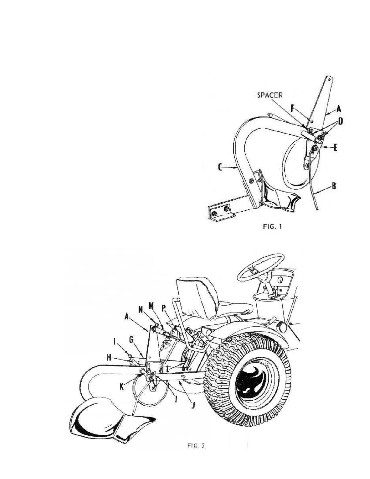
To increase the plowing depth, adjust the top linkage by turning adjusting screw (P, Fig. 2), to shorten the linkage. The
plow will go deeper until plow levels, and under normal conditions will hold that depth. This levels the plow and will leave
a level furrow bottom. Adjustment can be varied to give a better furrow turning.
Actually measure the width of the cut with a ruler to determine width of cut. This should be done where the furrow is
straight to get an accurate measurement. A depth of more than 6 inches is not recommended.
COULTER
The depth to which the coulter cuts is adjusted by raising or lowering the counter bracket with respect to the beam by the
three sets of holes provided.
When the ground is very hard, the coulter should be raised so that it will not interfere with depth of plowing. The blade
should run just deep enough to cut through all trash and leave a smooth furrow wall. When operating in soil where large
stones are prevalent, the coulter and bracket should be removed as a complete unit from the beam, to prevent the coulter
from holding or raising the plow bottom from the ground.
A grease fitting is provided in the coulter hub and should be greased before first operation and after every four hours of
operation. CAUTION: Care should be taken to avoid excessive pressure when greasing so as not to force hub cap off the
hub.
The cutting edge should be kept sharp at all times and can be sharpened by filing or grinding on an emery wheel. If the
coulter blade becomes rusty it should be repolished with 00 sandpaper and crocus cloth.
WEED ROD
The purpose of the weed rod is to aid in tuning under all weeds, grass, etc. It is adjustable by means of its attaching biolt.
It should be set according to the depth of plowing and material being turned under.
COUNTERWEIGHT
A front end counterweight should be attached to tractor if front end of tractor becomes too light and is difficult to steer in a
heavy pull.
TRACTION
Two wheel weights assembled to L.H. rear wheel is
necessary for satisfactory plowing. The L.H. rear wheel
runs on top of the unplowed ground. Most of the weight
of the tractor is shifted to the R.H. rear wheel. This is
the reason for assembling the two wheel weights to the
L.H. rear wheel to prevent it from slipping.
If wheels still slip, another weight can be added to R.H.
rear wheel, and a calcium chloride solution can be
added to both rear tires. This added weight will increase
the traction to about half the weight added. Refer to
wheel weight manual for assembly instructions.
another free manual from www.searstractormanuals.com

OPERATING INSTRUCTIONS – Continued
HEEL
The landside adjustable heel, refer to Figure 5, is made with
the rear hole slotted to enable the operator to adjust it to
compensate for ware and to increase suction in extremely
hard plowing conditions. A normal amount of suck is built into
the plow bottom. Figure 6 shows a plow bottom with 3/16
inch suck. Increase the suck by lowering the landside heel N,
Figure 5. This will give the plow a tendency to penetrate the
ground more readily.
For normal plowing operating the heel should be set in its
highest position. When plowing very hard o dry ground or if
the share has become worn, it may be difficult to get the plow
to penetrate the ground properly. In this case the heel may
be lowered slightly, see Figure 5. The distance that it can be
lowered must be determined by trial and error. In most cases
a slight adjustment at this point will be sufficient. If the share
has become badly worn and dull, it should be replaced.
PLOW SHARE
A dull or worn plow sharer is perhaps, the greatest cause of failure to do good plowing. The share may become worn
quickly, depending upon the type of soil encountered. Sand, rocks, and had dry, soil act as an abrasive and generally
wear the share faster than loam or ordinary black dirt. If the plow has a tendency to rise out of the ground, is unstable, o
will not penetrate to the desired depth we recommend that you check the amount of suction in the bottom and the curtin g
edge of the share to be sure that it is sharp. Measure the amount of suck as shown in Fig. 6. It should not be less thatn
1/16 of an inch.
A share that has become dull can be sharpened on an emery wheel by passing the share back and forth across the
wheel, engaging the area of the share shown in Fig. 7. Always grind the share from the underside as indicated.
If one of the following conditions should exist the share should be replaced with a new one.
1. Share has worn more than enough to cause it to lose suck. Measure the amount of suck as indicated above.
2. Plow shares have a tendency to wear off the cutting edge of the point, resulting in the area approximately ½ to 1 inch
behind the point engaging the ground. This results in a sled runner effect, and will hold the plow out of the ground.
another free manual from www.searstractormanuals.com

MAINTENANCE AND SERVICE – Continued
CARE OF PLOW BOTTOM
YOUR PLOW BOTTOM MUST BE KEPT IN A HIGH STATE OF POLISH AT ALL TIMES,
PROTECT IT FROM RUST BY COVERING IT WITH GREASE, OIL OR RUST PREVENTIVE
WHENEVER IT IS NOT IN USE.
Over Night Storage – Clean and cover moldboard, share, landside and coulter with heavy oil and store plow inside. If
unable to store plow inside cover same parts with grease.
Long Period Storage – Clean and cover all polished surfaces with a thick covering of grease or rust preventative, and stoe
in a dry area.
If the moldboard, share, or landslide should become rusted or otherwise mared, re-establish the finish by cleaning with 00
sandpaper and polishing with crocus cloth.
STORAGE
When the plow is to be stored for several days or longer, clean the bottom thoroughly and cover the moldboard, share,
landside and coulter with a heavy grease or rust preventative. Always keep plow in a dry area.
Sears Roebuck and Co. U.S.A. or Simpsons-Sears Limited in Canada reserves the right to make any changes in design
or improvements without imposing any obligations to install the same upon its items heretofore manufactured.
another free manual from www.searstractormanuals.com

NOTES
another free manual from www.searstractormanuals.com

another free manual from www.searstractormanuals.com

SEARS MOLDBOAD PLOW – MODEL NUMBER 917.253010
WHEN ORDERING REPAIR PARTS, ALWAYS GIVE THE FOLLOWING INFORMATION AS SHOWN IN THIS LIST:
1. THE PART NUMBER
2. THE PART NAME 3. THE MODEL NUMBER – 917.253010
4. THE NAME OF THE ITEM – PLOW
PARTS LIST
Do not use Illustration Numbers when ordering Repair Parts, always use Part Numbes.
KEY
NO. PART
NO. DESCRIPTION
16328E Coulter Blade
21513H1 Coulter Bracket
31514H2 Hitch Bracket
46324M Weed Rod
56327M Shoulder Bolt
66328M Coulter Hub
76335M Frog
86340M Heel
96341M Hub Cap
10 6342M Dust Cap
11 6343M Coulter Washer
12 6348M Bushing
13 6349M Felt Seal
14 6488M Spacer
15 6855M Grease Fitting
6 & 12 575PA223 Coulter Hub and Bearing
17 575PA224 Coulter Blade, Hub and Bearings
18 575PA226 Moldboard w/ Bolts
19 575PA227 Landside w/ Bolts
606A336A Plow Bottom, Complete
21 606A335A Share w/ Bolts
22 606A107A Beam and Hitch Bar
24 3000P Hex Bolt ½” x 1½” – 13NC
25 3001P Hex Bolt ½” x 1¾” – 13NC
26 25P Bolt, Sq. Neck Carr. ½” x 1¼” – 13
27 30P Bolt, Sq. Neck Plow –3/8” x 1” – 16
28 32P Bolt, Sq. Neck Plow –7/16” x 1¼” – 14
29 2P Bolt, Sq. Neck Plow –½” x 2” – 13
30 1500P Washer, Flat 17/32” x 11/16” x 13 Ga.
31 1544P Washer, Flat 15/32” x 15/16” x 16 Ga.
32 1000P Washer, Lock ½“
33 1001P Washer, Lock 7/16”
34 2000P Rivets, R.H. ¼” x 1¼”
35 500P Nut, Hex 7/16” – 14
36 501P Hex Nut 3/8– 16
37 502P Hex Nut ½ - 13
-- 9820H Instuction Sheet and Parts List for 917.253010
another free manual from www.searstractormanuals.com
Table of contents
Other Sears Lawn And Garden Equipment manuals

Sears
Sears BugWacker 557-5199 User manual

Sears
Sears 917.253311 User manual

Sears
Sears 486.244031 User manual

Sears
Sears Craftsman 316.794450 User manual

Sears
Sears Craftsman 900 Series User manual

Sears
Sears 917.252031 User manual

Sears
Sears 180.260250 User manual

Sears
Sears 917.250550 User manual

Sears
Sears 486.244062 User manual
Popular Lawn And Garden Equipment manuals by other brands

Craftsman
Craftsman 486.248474 Operator's manual

Stratco
Stratco HOMESHEDS Assembly instructions

Makita
Makita DUM604SFX instruction manual

Liberty Garden
Liberty Garden 870 owner's manual

plastia
plastia Urbalive Berberis DUO Assembly instructions

Protect
Protect GB-16L USER MANUAL, INSTALLING AND OPERATING MANUAL