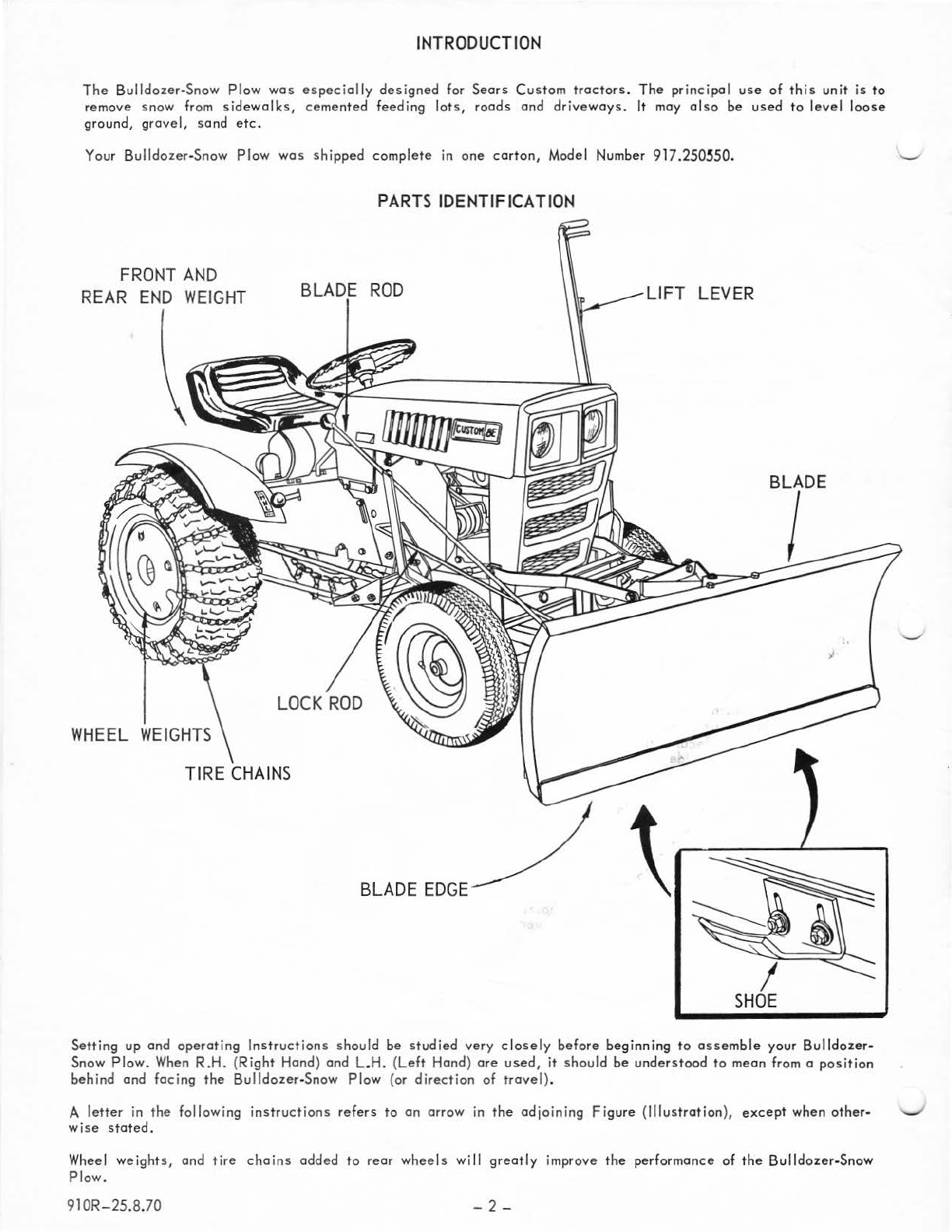
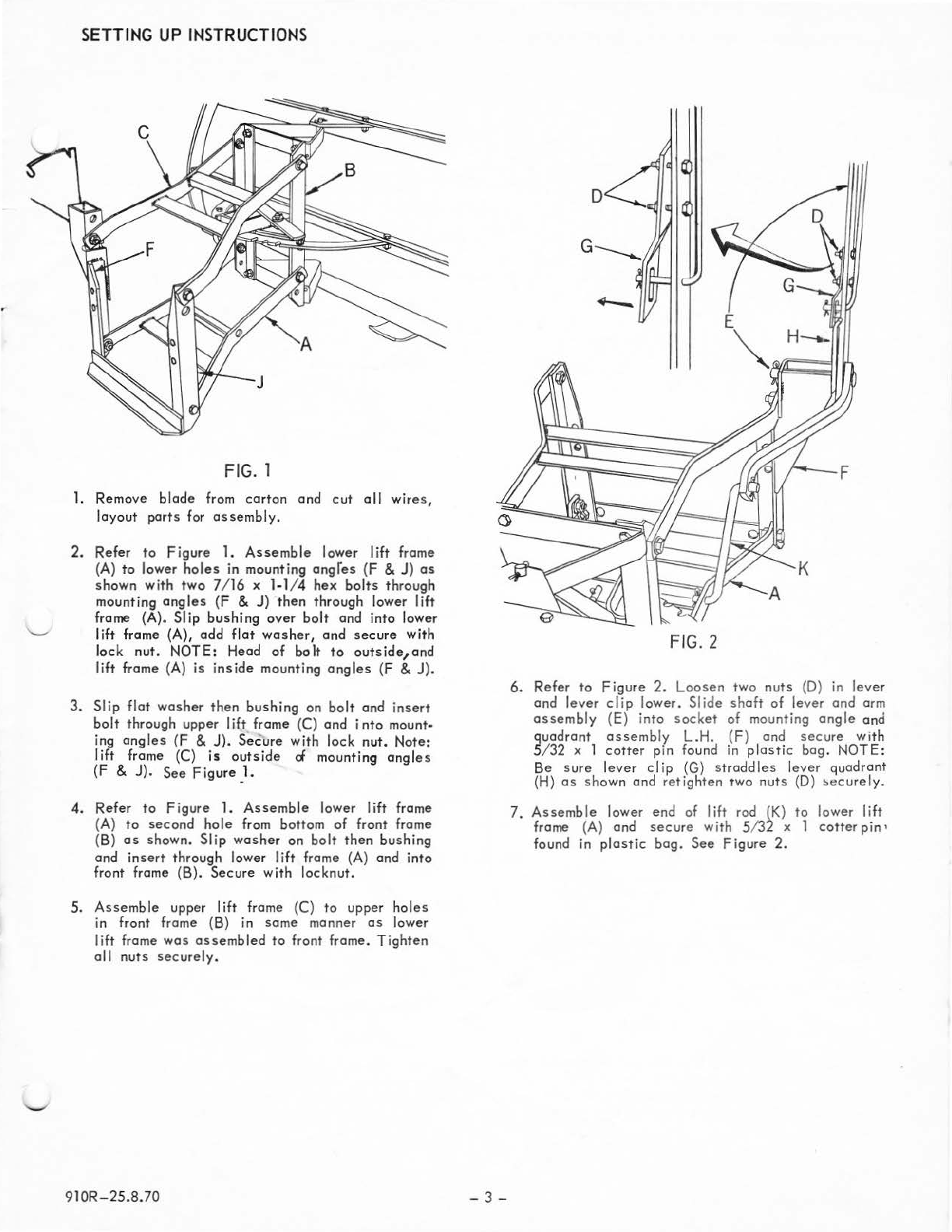
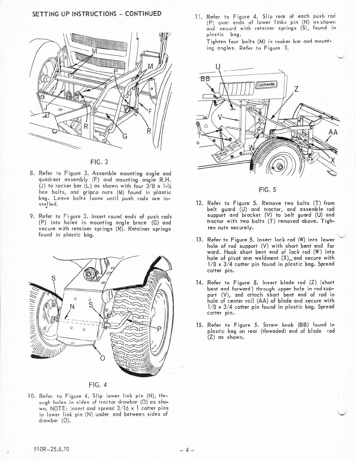
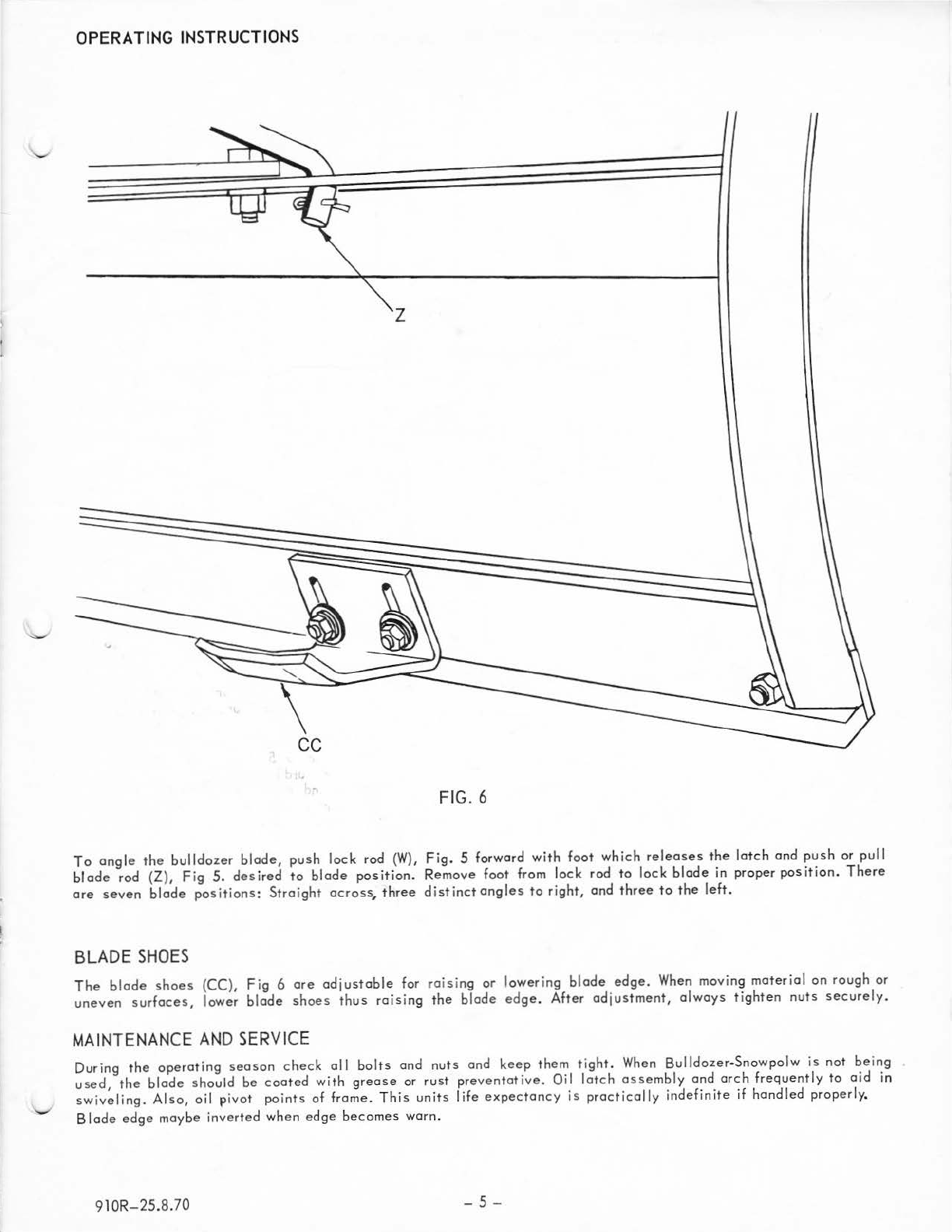
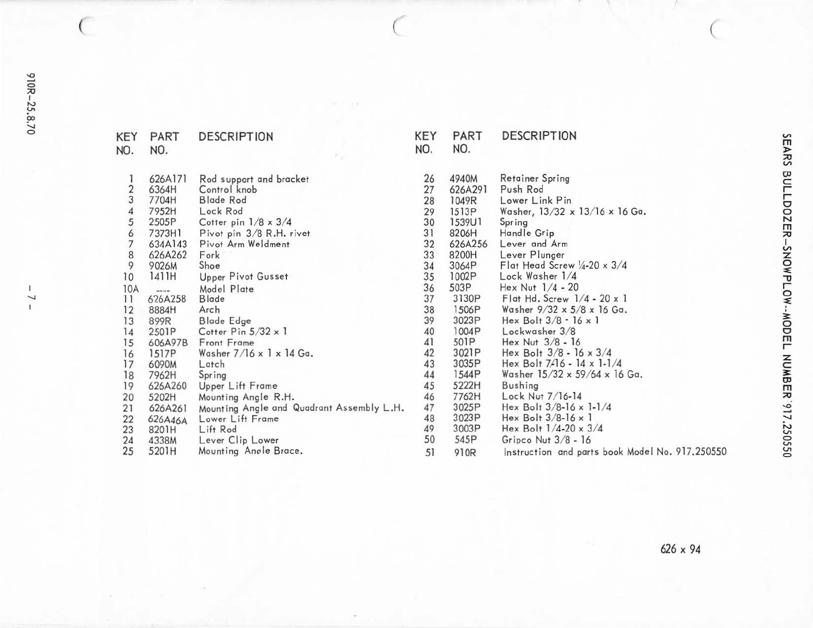
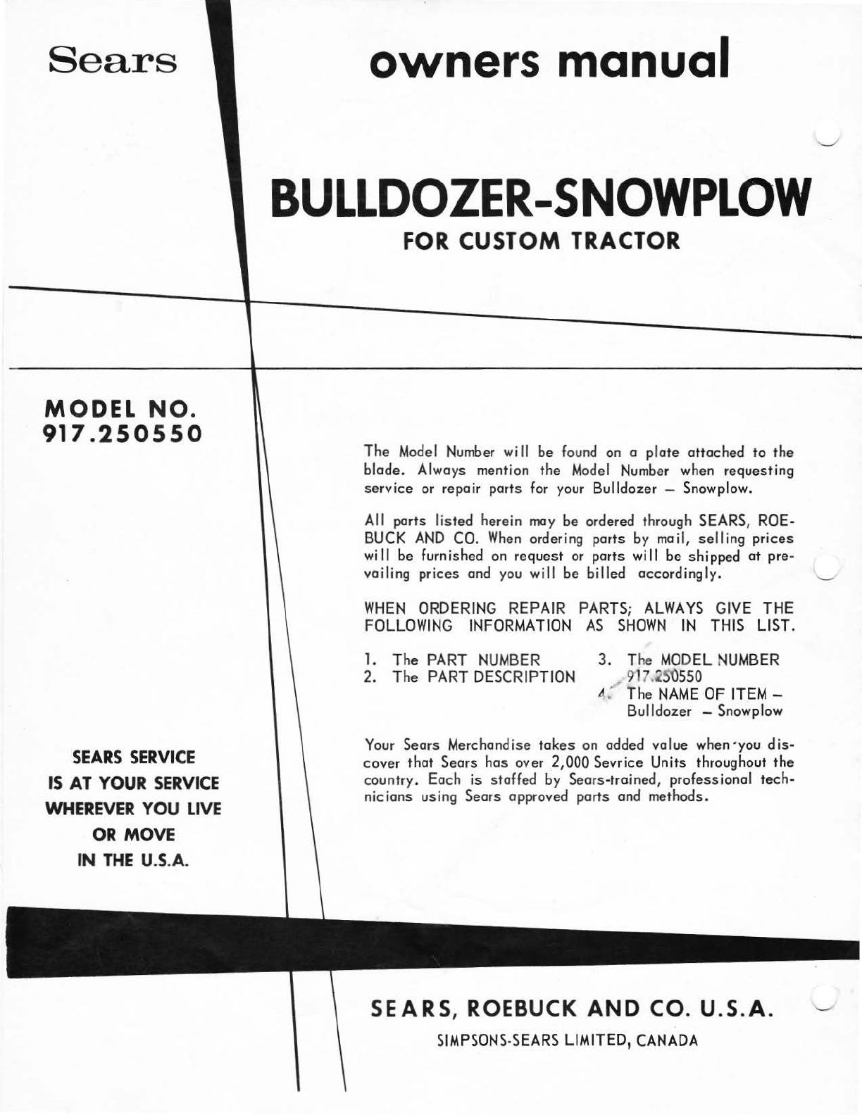
Sears 917.250550 User manual

Sears
MODEL
NO.
917.2505
50
":
.
!\UTI
ON:
'------'
Read
:'ules
for
Safe
Operation
and
lnstrut
tions
Carefully
•
Assembly
•
Operating
•
Maintenance
•
Repair
Parts
owners
manual
BULLDOZER-SNOWPLOW
FOR
CUSTOM
TRACTOR
SEARS,
ROEBUCK
AND CO. U.S.A.
SIMPSONS-SEARS
LIMITED,
CANADA
Pr
inted in U.SA.
another free manual from www.searstractormanuals.com

INTRODUCTION
The
B
ulldozer
-Snow
Plow
was
especially
designed
for
Sears
C
ustom
tractors.
The
principal
use
of
this
unit
is
to
remove
snow
from
sidewalks,
cement
ed
feeding
lots,
roods
and
driveways.
It
may
also
be
used
to
level
loose
ground,
grovel,
sand
etc.
Your
Bulldozer-Snow
Plow
was
shipped
complet
e in
one
carton,
Model Number
917.250
5
50.
FRONT
AND
REAR
END
WEIGHT
WHEEL
WEIGHTS
PARTS
IDENTIFICATION
BLADE
ROD
LIFT LEVER
BLADE
EDGE
BLADE
I
Setting
up
and
operating
Instructions
should
be
studied
very
closely
before
beginning
to
assemble
your
Bulldozer-
Snow
Plow
. When
R.H.
(R
ight
Hand)
and
L.H.
(L
eft
Hand)
ore
used,
it
should
be
understood
to
mean
from a
position
behind
and
facing
the
Bulldozer-Snow
Plow
(or
direction
of
travel)
.
A
letter
in
the
following
instr
uctions
refers
to
on
arrow
in
th
e
adjoining
Figu
re
(Illust
ration
),
except
when
other-
wise
stated.
Wh
eel
weight
s,
and tire
chains
added
to
rear
wheels
will
greatly
imp
rove
the
performance
of
the
Bulldozer
-Snow
Plow.
910R-25.8.70
-2
-
another free manual from www.searstractormanuals.com

SE
T
TING
UP
IN
ST
RUCTIO
NS
FIG. 1
1.
Remove
blade
from
carton
and
cut
all
wi
res,
layout
parts
for
assembly
.
2.
Refer
to
Fi
gure
1.
Assemble
lower
lift
frame
(A)
to
lower
holes
in
mounting
angres
(F & J)
as
shown
wi
th
two
7/ 16 x
1-1/4
hex
bolts
through
mounting
angles
(F
&
J)
then
through
lower
lift
frame (A).
Slip
bushing
over
bolt
and
into
lower
lift
frame (A),
add
flat
washer,
and
secure
with
lock
nut.
NOTE:
Head
of
bo
It
to
outside_,and
lif
t frame (A)
is
inside
mounting
angles
(F & J).
3.
Slip
flat
washer
then
bushing
on
bolt
and
ins
ert
bolt
th
rough
upper
I
ift
frame (C) and
into
mount-
ing
angles
(F
& J).
Secure
with
lock
nut.
Note:
lift
frame (C)
is
outside
d mounting
angles
(F
& J).
See
Figure
_1.
4.
Refer
to
Fi
gure
1.
Assemble
lower
lift
frame
(A)
to
second
hole
from bottom
of
front
frame
(B)
as
shown.
Sl ip
washer
on
bolt
then
bushing
and
insert
through
lower Iift frame (A) and
into
front frame
(B).
Secure
with
locknut.
5.
Assemble
upper
lift
frame (C)
to
upper
holes
in
front
frame (B) in
same
ma
n
ne
r
as
lower
lift
frame
wa
s
assembled
to
front
frame.
Tighten
all
nuts
securely
.
910R-25.8.70
-3-
FIG. 2
6.
Refer
to
Figure
2.
Loosen
two
nuts
(D) in
lev
er
and
lever
clip
lower.
Slide
sh
aft
of
lever
and
arm
as
se mbly (E)
into
socket
of
mounting
angle
and
quadrant
asse
mbly L.H. {F) and
secure
wi
th
5
/3
2 x 1
cotte
r pin found in
plastic
bag.
NOTE
:
Be
sure
lever
clip
(G)
str
addles
lever
quadrant
(H)
as
sh
own
an
d
retighten
rwo
nuts
(D)
~ecurel
y.
7.
A
ssemble
lower end of Iift rod (K)
to
lower
lift
frame (A)
and
secure
with
5132 x 1
cotte
r
pin'
fou
nd
in
plastic
bag.
See
Fi
gure
2.
another free manual from www.searstractormanuals.com

SETTING
UP
I
NS
TR
UCTI
ONS
- C
ONT
I
NUED
FIG.
3
8.
Refer
to
Figure
3.
Assemble
mounting
angle
and
quadrant
assembly
(F)
and
mounting
angle
R.H.
(J)
to
rocker
bar
(L)
as
shown
with
four
3/8
x
1-y,j
hex
bolts,
and
gripco
nuts
(M)
found in
plastic
bag.
Leave
bolts
loose
until
push
rods
are
in·
stalled.
9.
Refer
to
Figure
3.
Insert
round
ends
of
push
rods
(P)
into
holes
in mounting
angle
brace
(G)
and
secure
with
retainer
springs
(R).
Retainer
springs
found in
plastic
bag.
FIG.
4
10.
Refer
to
Figure
4.
Slip
lower
link
pin
(N),
thr·
ough
holes
in
sides
of
tractor
drawbar
(0)
as
sho-
wn.
NOTE:
Insert
and
spread
3/ 16 x 1
cotter
pins
in lower
link
pin
(N)
under
and
between
sides
of
drawbar
(0}.
910R-25.8.70
-4-
11.
Refer
to
Figu
re
4.
Slip
rear
of
each
push
rod
(P)
over
ends
of
lower
I
inks
pin
(N)
as
shown
and
securd
with
retainer
springs
(S),
found
in
plastic
bag.
Tighten
four
bolts
(M)
in
roo
ker
bar
and
mount·
ing
angles.
Refer
to
Figu
re
3.
FIG.
5
12.
Refer
to
Figure
5.
Remove
two
bolts
(T) from
belt
guard
(U)
and
tractor,
and
assemble
rod
support
and
bracket
(V)
to
belt
guard
(U}
and
tractor
with
two
bolts
(T)
removed
above
. T
igh·
ten
nuts
securely.
13.
Refe
r
to
Figure
5.
Inse
rt
lock
rod
(W)
into
lower
hol
e
of
rod
support
(V)
with
sho
rt
bent
end
for
ward. Hook
short
bent
end
of
lock
rod (W)
into
hole
of
pivot
arm
weldment
(X),.
and
secure
with
1/8
x
3/4
cotter
pin
found
in
plastic
bag.
Spread
cotter
pin.
1
4.
Refer
to
Figure
5.
Insert
blade
rod
(Z)
(short
bent
end
forwar
d)
through
upper
hole
in rod
sup
·
port
(V),
and
attach
short
bent
end
of
rod in
hole
of
center
rail
(AA)
of
blade
and
secure
with
1/8
x
3/4
cotter
pin
found
in
plastic
bag.
Spread
cotter
pin.
1
5.
Refer
to
Figure
5.
Screw
knob (BB) found in
plastic
bag
on
rear
(threaded}
end
of
blade
rod
(Z)
as
shown.
another free manual from www.searstractormanuals.com

OPERATING
INSTRUCTIONS
z
FI
G.
6
To
angle
the
bulldozer
blade,
push
loc
k rod
(W),
Fig.
5 forward
with
foot
which
releases
the
latch
and
push
or
pull
bl
ade
rod (Z),
Fig
5.
desired
to
blade
position.
Remove
foot
from
lock
rod
to
lock
blade
in
proper
position
.
There
are
seven
blade
positions:
Straight
across,
three
distinct
angles
to
right,
and
three
to
the
left
.
BL
AD
E
SHOES
The
blade
shoes
(CC),
Fig
6
are
adjustable
for ra1s1ng
or
lowering
blade
edge.
When moving
material
on
rough
or
uneven
surfaces,
lower
blade
shoes
thus
raising
the
blade
edg
e.
After
adjustment,
always
tighten
nuts
securely.
MAINTENANCE
AND
SERVICE
During
the
operating
season
check
all
bolts
and
nuts
and
keep
them
tight.
When Bu
lldo
zer
-Snowpolw
is
not
being
used,
the
blade
should
be
coated
with
grease
or
rust
preventat
ive.
Oil
latch
assembly
and
arch
frequently
to
aid
1n
swiveling.
Also,
oil
pivot
points
of
frame.
This
units
life
expectancy
is
prac
tically
indefinite
if
handled
properly
.
Blade
edge
maybe
inverted
when
edge
becomes
warn.
91
OR
-25
.8.
70
-5-
another free manual from www.searstractormanuals.com

':£
0
::0
I
tV
VI
?>
-...J
0
I
0..
I
A
~
2
I -
-====~===-=-
·-
.g -
-'
3
:
""
5
'
_;
- -
..
--
0101:>....._5
-
---
0 :
---
--
--
6
-u
,
--
' '
-
---
7¢
,I 5
I
-~
8 I
_
,_~
--
-
~
s
-
~
1
:-
~-
-
~
·-
=
a
r-~
~
~
-
• ; o I •
,
......
........
' '
--,
t(
---~
v·
. 9 l
14 c •
18 E,-
15---l
r _
ii'J.
21
9
i 8 s"
.t
~
- -
.
~
...
t;J
___
__
s16
1
I o -
-,.
•
--
I Q I
E.'
--
----~
22
I._ I • t
-I
14
-:_:_::.;.,1
~
~
: :
~
...._
I
I
'-J
I
~
A 8 C D E F G
'
H
/
/
I
F
e-
32
20
/
~
--
====
==--'~
i34
,37
'39
,42
,43
147
@
35
@38 @
40
®
40
@)
44
,48
@40
@41
,49
~35
@36
~
v"
31
5
-
2~
--
HA
-=
7
1(-
rr l
@
36
~35
@
41
@4
1
{9
45
@
0
50
~36
~46
IL
7
[_
__
,'
29
Jo
29
33
( (
&
V\
m
)>
:::0
V\
o:J
c
r
r
0
0
N
m
:::0
I
V\
z
0
:::E
-o
r
0
~
I
I
3:
0
0
m
r
z
c
3:
o:J
m
:::0
'-0
'J
N
VI
0
VI
VI
0
another free manual from www.searstractormanuals.com

( (
"'
-
0
;o
I
N
(.n
(X)
~
0
KEY
PART
DESCRIPTION
KEY
PART
DESCRIPT
I
ON
~
NO.
NO.
NO.
NO.
m
)>
;:u
~
1
626A
171
Rod
support and brocket
26
4940M
Retainer Spring
OJ
c:
2
6364H
Control
knob
27
626A291
Push
Rod
r
3
7704H
Blade
Rod
28
1049R
Lower Link Pin r
0
4
7952H
Lock
Rod
29
1513P Washer,
13
/3
2 x
13
/
16
x 16
Go.
0
5 2505P Cotter pin 1
/8
x 3/ 4 30 1539Ul Spring N
m
6
7373H
1 Pivot pin 3
/8
R.H
. rivet 31
8206H
Handle Grip ;:u
7
634A
143
Pivot
Arm
Weldment
32
626A256 Lever and
Ar
m I
8 626A262 Fork 33
8200H
Lever PIunger
~
z
9
9026M
Shoe
34
3064P
Flat
Head Screw
~-20
x 3/ 4 0
10
14
11H
Upper
Pivot Gusset 35 1002P Lock Washer 1/4
~
-u
lOA
.........
Model
Plate 36 503P
Hex
Nut
1/4
-20 r
'-I
11
6'26A258
Blade
37
3130P Flat
Hd.
Screw
1/4-
20
x 1 0
~
I
12
8884H
Arch
38 1506P Washer 9/
32
x 5/ 8 x
16
Go
. I
I
13
899R Blade Edge
39
3023P
Hex
Bolt 3/ 8 •
16
x 1
~
0
14
2501P Cotter Pin 5/
32
x 1 40 1004P Lockwosher 3/ 8 0
15
606A97B Front Frome 41 501P
Hex
Nut
3/ 8 - 16 m
16
1517P Washer 7/
16
x 1 x 14
Go.
42
3021p
Hex
Bolt 3/ 8 -
16
x 3/ 4 r
z
17
6090M
Latch 43 3035P
Hex
Bolt
7J16-
14
x 1-
1/4
c:
18
7962H
Spring 44 1544P Washer
15
/32 x
59
/
64
x
16
Go.
3:
19
626A260 Upper Lift Frome 45
5222H
Bushing
OJ
m
20
5202H
Mounting Angle R.H. 46
7762H
Lock Nut 7/
16
-1
4 ;:u
21
626A261
Mounting
Angle and Quadrant Assembly L.H.
47
3025P
Hex
Bolt 3/
8-
16 x 1-1/4
-o
__,
22
626A46A
Lower Lift Frome 48 3023P
Hex
Bolt 3/ 8-
16
x 1
-.....!
23
8201H
Lift
Rod
49
3003P
Hex
Bolt 1/4-20 x 3/4 N
V1
24
4338M
Lever Clip Lower
50
545P Gripco
Nut
3/ 8 -
16
0
V1
25
5201H
Mounting Anole Broce.
51
910R
Instruction and ports
book
Model
No.
917.250550
V1
0
626
X
94
another free manual from www.searstractormanuals.com

Sear
s
MODEL
NO.
917.2505
50
SEARS
S
ERVI
CE
IS
AT
YOUR
SERV
I
CE
WHEREV
ER
Y
OU
LIVE
OR
MO
VE
IN
THE
U.S.
A.
owners manual
BULLDOZER-SNOWPLOW
FOR
CUSTOM
TRACTOR
The
Model
Number
wi
II
be
found
on
a plate
attached
to
the
blade.
Always
mention
the
Model
Number
when
requesting
service
or
repair
ports
for
your
Bulldozer -
Snowplow.
All
parts
listed
herein
may
be
orde
r
ed
through
SEARS,
RO
E-
BUCK
AND
CO.
When
ordering
ports
by
moil, selling prices
will
be
furnished
on
request
or
parts
will
be
shippe
d at pre-
vailing prices
and
you
will
be
billed accordingly.
WHEN
ORDERING
REPA
IR
PARTS;
ALWAYS
GIVE
THE
FOLLOWING
INFORMATION
AS
SHOWN
IN
THIS
LI
ST
.
1.
The
PART
NUMBER
3.
T
he
MODEL
NUM
BE
R
2.
The
PART
DESCRIPTION
_..
917
.
~5()
550
4.'
The
NAM
E·OF I
TEM
-
Bulldozer -
Snowplow
Your
Sears
Merchandise
tokes
on
added
value
when
·you
dis-
cover
that
Sears
has
over
2,000
Sev
rice
Un
it
s thr
ougho
ut
the
country.
Each
is staffed
by
Sears
-trained,
profess
i
on
al t
ech-
nicians
using
Sears
approved
ports
and
methods.
SEARS
, ROEBUCK
AND
CO.
U.S.A .
SIM
P
SONS-S
E
ARS
LIMI
TED,
CANA
DA
another free manual from www.searstractormanuals.com
Table of contents
Other Sears Lawn And Garden Equipment manuals

Sears
Sears 917.253311 User manual

Sears
Sears Craftsman 316.794450 User manual

Sears
Sears 486.244062 User manual

Sears
Sears Craftsman 900 Series User manual

Sears
Sears 917.253010 User manual

Sears
Sears 917.252031 User manual

Sears
Sears 486.244031 User manual

Sears
Sears 180.260250 User manual

Sears
Sears BugWacker 557-5199 User manual
Popular Lawn And Garden Equipment manuals by other brands

Craftsman
Craftsman 486.248463 owner's manual

CAMPAGNOLA
CAMPAGNOLA T-REX quick guide

Perel
Perel GMK2LAMP user manual

Everbloom
Everbloom R1421E4821 installation guide

Woodland
Woodland WOODLAND SCENICS JUST PLUG JP5950 instructions

New England Arbors
New England Arbors The 4x4 Composite Garden Bed Assembly instructions