OPERATING
INSTRUCTIONS
BEFORE
CUTTING
AN
UNFAMILIAR
PLOT
OF
GRASS,
ALWAYS
STOP
TO
ANALYZE
THE
LAWN
OR
FIELD
FOR
BEST
MOWING
PROCE-
DURE.
CONSIDER
ALSO
THE
HEIGHT
OF
GRASS
TO
BE
MOWED.
TYPE
OF
TERRAIN
(LEVEL,
HILLY
OR
PITTED),
AS
WELL
AS
THE
PRESENCE
OF
ROCK
OR
TRASH.
EACH
CONDITION
WILL
REQUIRE
CERTAIN
AD-
JUSTMENTS
OR
PRECAUTIONS
AS
OUT-
LINED
IN
THIS
MANUAL.
I
/
DO
NOT
STOP
OR
START
SUDDENLY
WHEN
GOING
UPHILL
OR
DOWNHILL.
OPERATE
MOWER
UP
AND
DOWN
THE
FACE
OF
SLOPES;
NEVER
ACROSS
THE
FACE.
NEVER
OPERATE
MOWER
ON
SLOPES
WITH
MORE
THAN
A
15
DEGREE
SLOPE.
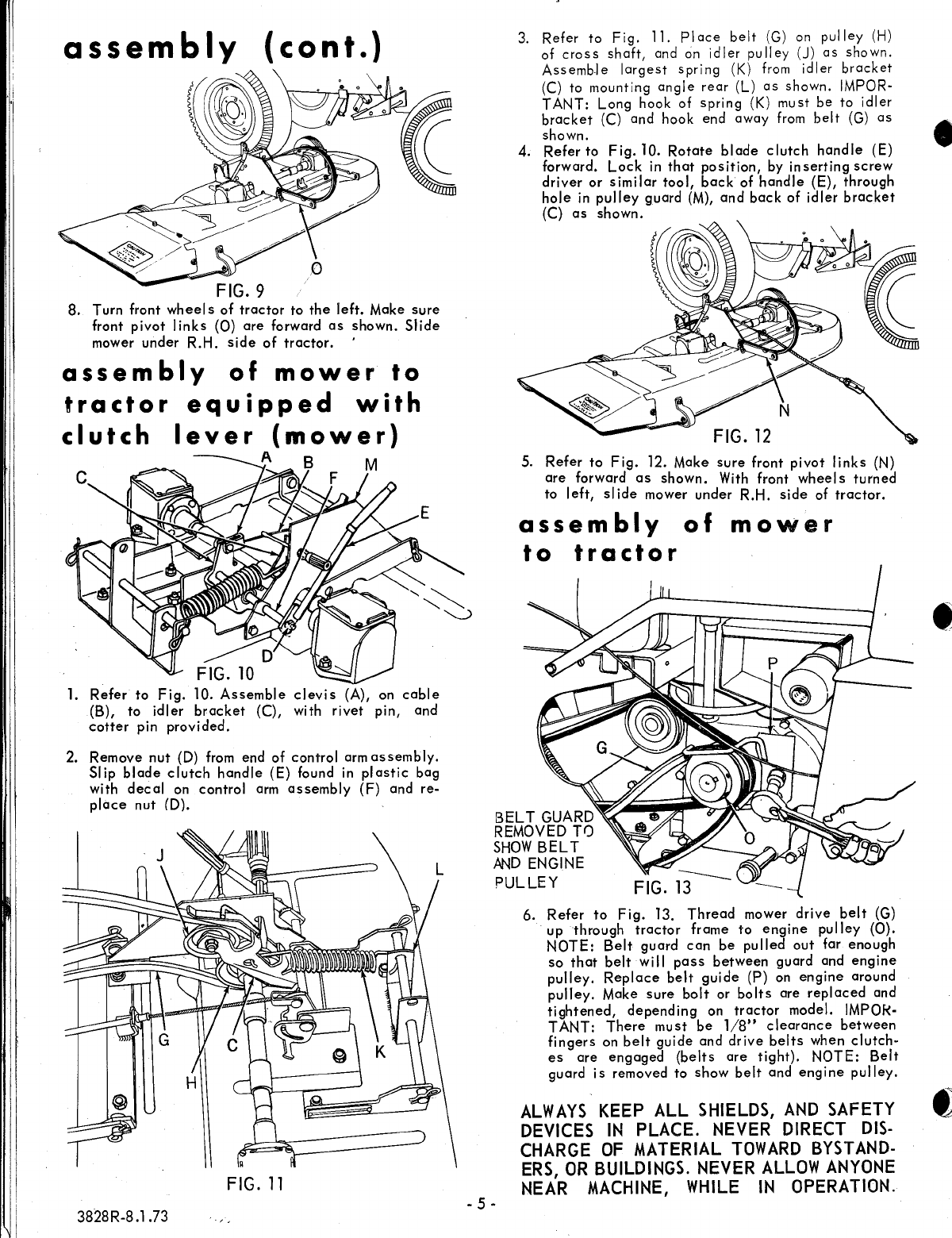
The
blade
clutch
handle
is
located
at
right
hand
of mower on
cutter
head
or on R.H.
side
of
tractor
frame
depending
on
tractor.
The
blade
clutch
handle
engages
the
mo
wer
bl
ades.
1.
Set
engine
speed
to
about
half
throttle
before
engaging
or
disengaging
mower.
In
either
case,
engage
or
disengage
blade
.clutch
handle
slowly.
After
mower
is
engaged,
set
to
full
throttle.
Caution:
Never
engage
mower
except
when
sit-
ting on
tractor
seat,
and
keep
hands
and
feet
from
beneath
the
housing.
After mower
is
engag-
ed,
advance
throttle
lever
to full
throttle.
2.
Push
down on foot
pedal
and move
gear
shift
lever
to
speed
desired.
Normal
cutting
speed
is
1
st
gear
on a
three
speed
custom
tractor,
2nd
gear
011
a four
speed
custom
tractor,
or 3rd
gear
low
range
on a
eight
speed
custom
tractor.
If
engine
pulls
down,
shift
to
a lower
gear
on four
and
eight
speed
tractors,
and
cut
less
than
a
full width
cut
on a
three
speed
custom.
In
ex-
treme
heavy
cutting
it
may
be
necessary
to
use
the
lowest
gear
and
take
a narrower
cut.
Do
not
operate
the
tractor
in
high
gear
going
down
hill',
and
do
not
turn
sharp corners
while
going
down
hill.
If
it
is
necessary
to
stop tractor
while
going
down
hill,
do
so quickly
to
prevent
tractor
from
picking
up
speed
during
the
de-
clutching
to
braking operation.
NOTE:
The
engine produces considerable
braking
action
when
throttled back
to
idling
speed
without
de-
clutching,
and
this
procedure
is
recommended
before
applying brake.
3. Normal
cutting
height
is
'1-7/8
inches,
height
of
cut
can
be
adjusted
by
means
of
lift
lever.
Mov-
ing
the
lever
forward
lowers
the
mower
wh
iIe
moving
it
backwards
raises
the
mower. '
With
lift
lever
set
to
height
of
cut
desired
and
with
tractor
and mower on
level
ground,
adjust
gauge
wheel
s
so
that
they
c
lear
the
ground by
approximately
Y2
inch.
3828R-8.1.73
- 8 -
4. Make
left
hand
turn s when mowing,
this
spreads
the
grass
clippings
evenly
over
the
grass
which
has
been
cut.
Grass
is mowed
regularly
(do
not
let
grass
get
too
high),
there
is
little
or
no
raking
necessary
after
mowing.
WHEN
MOWING
NEXT
TO
BUILDINGS OR
FLOWER
BEDS
THE
TRACTOR
SHOULD
BE
DRIVEN SO
THAT
THE
DISCHARGE
OF
MOWER
WILL
BE
AWAY
FROM BUILDING OR FLOWER
BED.
Do
not
shift gears while
going
up
steep
hi
lis.
Choose a
low
enough
gear
to
cI
imb
h
ill
without
stopping
and
shifting gears. If
it
is necessary
to
stop
while
going
up
hill,
do
so quickly
to
prevent tractor
roll
ing
backward.
When
start
ing
tractor
in
motion
going
up
hill,
use
one
of
the
lowest gears, reduce engine speed
and
engage
clutch gradually
to
prevent tractor
from
"rearing
up".
maintenance
lubrication
FIG.
23
1.
Check
grease
in
gear
boxes
after
each
fifty
hours
of
operation.
Each
gear
box
shou
Id
be
approximately
Y2
full.
Lubrication
-
Gear
case
moly
E.P.
lithium
grease
4
oz.
required
in
each
gear
box.
Can
be
purchased
from
Sears
automotive
department.
2.
To
check,
remove
gear
box
cover
by
unscrewing
4
screws.
See
Figure
23.
3.
Refer
to
Page
6,
Fig.
16.
Lubricate
cable
with
light
oil,
twice
a
year.
another free manual from www.searstractormanuals.com