manuals.online logo
Brands
  1. Home
  2. •
  3. Brands
  4. •
  5. ASCO Valves
  6. •
  7. Control Unit
  8. •
  9. ASCO Valves 8210 Series Installation and operating instructions

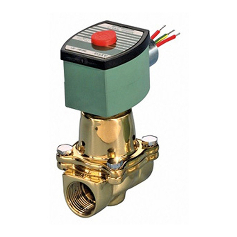
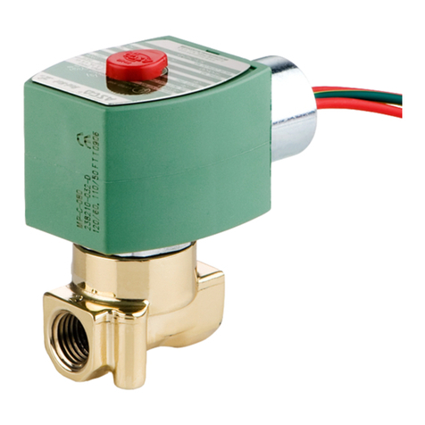
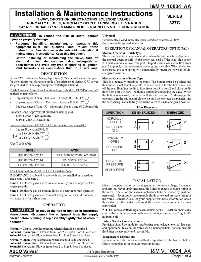
ASCO Valves 8210 Series Installation and operating instructions

ASCO Valves® E268269 - 10/2016 All Rights Reserved I&M V_5590_R5
©ASCO Valve, Inc.50 Hanover Road, Florham Park, New Jersey 07932 www.ascovalve.com Page 1 of 3
I&M V_5590_R5
Installation & Maintenance Instructions
2-WAY INTERNAL PILOT OPERATED SOLENOID VALVES
DIAPHRAGM TYPE 3/8", 1/2"AND 3/4"NPT
NORMALLY CLOSED OPERATION - HOT WATER SERVICE
SERIES
8210
8211
DESCRIPTION
Series 8210 valves with Suffix “HW” in the catalog number are 2-way,
internal pilot operated solenoid valves designed specifically for hot
water service. Standard valves have a General Purpose, NEMAType
1 Solenoid Enclosure.
Series 8211 valves are the same as Bulletin 8210 valves except the
solenoids are equipped with an enclosure which is designed to meet
NEMA Type 4 - Watertight, NEMA Type 7 (C or D) Hazardous
Locations - Class II, Group E, F or G. Installation and Maintenance
Instructions for this enclosure are provided on I&M Nos. V5380 and
V5391.
Notice: Standard brass valves are not certified as lead-free under
the Safe Drinking WaterAct SDWA1417 and are not intended for
use on drinking water systems. They are intended for control of
water in industrial applications. Consult ASCO for valves rated
for use in potable water applications.
Notice: Constructions with an “LF” suffix meet the lead free-brass
requirement of SDWA 1417 having 0.25% or less lead (Pb) in
brass. Due to the variety of operating conditions and applications
of these products, the user, through analysis and testing, is solely
responsible for making the final selection of the products and
assuring that all performance, safety, and warning requirements
of the applications are met.
OPERATION
Normally Closed: Valve is closed when solenoid is de-energized and
opens when solenoid is energized
IMPORTANT: Minimum operating pressure differential is 5 PSI.
Manual Operator (Optional)
Valves with Suffix “MO” in catalog number are provided with a
manual operator which allows manual operation when desired or
during an interruption of electrical power. To operate valve manually,
push in knurled cap and rotate clockwise 180°. Disengage manual
operator by rotating knurled cap counterclockwise 180° before
operating electrically.
Manual Operator Location (Refer to Figures 1 and 2)
Manual operator (when shipped from factory) will be located over the
valve outlet. Manual operator may be relocated at 90° increments
by rotating valve bonnet. Remove bonnet screws (4) and rotate valve
bonnet with solenoid attached to desired position. Replace bonnet
screws (4) and torque in a crisscross manner to 95 ± 10 inch pounds.
If valve is installed in system and is operational, proceed in the
following manner:
WARNING: Depressurize valve and turn off
electrical power supply.
AVERTISSEMENT: Dépressuriser la vanne et
couper l’alimentation électrique.
1. Remove retaining cap or clip and slip the entire solenoid enclosure
off the solenoid base sub-assembly.
CAUTION: When metal retaining clip disengages, It will
spring upward.
ATTENTION: Lorsque le clip de maintien métallique est
dégagé de sa position, il va s’éjecter vers l’extérieur.
2. Remove bonnet screws (4) and rotate bonnet to desired position.
3. Replace bonnet screws (4) and torque in a crisscross manner to 95
± 10 inch pounds.
4. Replace solenoid enclosure and retaining cap or clip.
Temperature Limitations (Optional)
For maximum valve ambient and fluid temperatures, refer to chart
below or as limited by solenoid approvals. See solenoid installation
and maintenance instructions. The temperature limitations listed
are for UL applications. For non UL applications, higher ambient
temperature limitations are available. Consult factory. Check catalog
number on nameplate to determine maximum temperatures.
Coil
Class Catalog Number
Prefix Max. Amb. Temp.
°F Max. Fluid Temp.
°F
A None or DA 77 210
F DF or FT
H HT 122 210
Positioning/Mounting (Refer to Figures 3 and 4)
This valve is designed to perform properly when mounted in any
position. However, for optimum life and performance, the solenoid
should be mounted vertical and upright so as to reduce the possibility
of foreign matter accumulating in the core tube area. For mounting
bracket dimensions (optional feature) refer to Figures 3 and 4.
Piping
Connect piping to valve according to markings on valve body,
CAUTION: Valves with Suffix “HW” in the catalog number
have a special diaphragm material which is specifically
compounded for hot water service. This material can be
attacked by oil and grease. Wipe the pipe threads clean of
cutting oils and use PTFE tape to seal pipe joints.
ATTENTION: Les vannes avec un suffixe « HW » dans le
numéro de catalogue sont équipées d’un diaphragme
spécial dont le matièrau est spécifiquement conçu pour
l’utilisation avec de l’eau chaude. Ce matériau peut être
attaqué par l’huile et la graisse. Essuyer les filetages des
canalisations pour éliminer les huiles de coupe et utiliser
de l’adhésif PTFE pour sceller les joints des canalisations.
Pipe strain should be avoided by proper support and alignment of
piping. When tightening pipe, do not use valve as a lever. Wrenches
applied to valve body or piping are to be located as close as possible
to connection point.
IMPORTANT: For the protection of the solenoid valve, install a
strainer or filter suitable for the service involved in the inlet side
as close to the valve as possible. Periodic cleaning is required
depending on the service conditions.
Wiring
Wiring must comply with Local and National Electrical Codes.
For valves equipped with an explosion-proof/watertight solenoid
enclosure, the electrical fittings must be approved for use in the
approved hazardous locations. Housings for all solenoids are provided
with connections for 1/2 inch conduit. The general purpose solenoid
enclosure may be rotated to facilitate wiring by removing the retaining
cap or clip.
CAUTION: When metal retaining clip disengages, it will
spring upward. Rotate to desired position. Replace retaining
cap or clip before operating.
ATTENTION: Lorsque le clip de maintien métallique
est dégagé de sa position, il va s’éjecter vers l’extérieur.
Le faites pivoter vers la position souhaitée. Replacer le
capuchon ou clip de maintien avant d’actionner la vanne.
Page 2 of 3 I&M No. V_5590_R5
©ASCO Valve, Inc.50 Hanover Road, Florham Park, New Jersey 07932 www.ascovalve.com
Solenoid Temperature
Standard catalog valves are supplied with coils designed for continuous
duty service. When the solenoid is energized for a long period, the
solenoid enclosure becomes hot and can be touched with the hand only
for an instant. This is a safe operating temperature. Any excessive
heating will be indicated by the smoke and odor of burning coil
insulation.
MAINTENANCE
WARNING: Turn off electrical power supply
and depressurize valve before making repairs. It
is not necessary to remove valve from pipe line
for repairs.
AVERTISSEMENT: Couper l’alimentation
électrique et dépressuriser la vanne avant
d’effectuer des réparations. Il n’est pas
nécessaire de retirer la vanne de la canalisation
pour effectuer des réparations.
Cleaning
Aperiodiccleaningofallsolenoidvalvesisdesirable.Thetimebetween
cleanings will vary, depending on media and service conditions. In
general, if the voltage to the coils is correct, sluggish valve operation,
excessive leakage or noise will indicate that cleaning is required. Be
sure to clean valve strainer or filter when cleaning solenoid valve.
Preventive Maintenance
• Keep the medium flowing through the valve as free from dirt and
foreign material as possible
• While in service, operate valve at least once a month to insure
proper opening and closing.
• Periodic inspection (depending on media and service conditions) of
internal valve parts for damage or excessive wear is recommended.
Thoroughly clean all parts. Replace any parts that are worn or
damaged.
Causes of Improper Operation
• Faulty Control Circuit: Check electrical system by energized
solenoid. A metallic click signifies the solenoid is operating.
Absence of the click indicates loss of power supply. Check for
loose or blown-out fuses, open circuited or grounded coil, broken
lead wires or splice connection.
• Burned-Out Coil: Check for open circuited coil. Replace coil if
necessary.
• Low Voltage: Check voltage across coil leads. Voltage must be at
least 85% of nameplate rating.
• Incorrect Pressure: Check valve pressure. Pressure to valve must be
within range specified on nameplate
• Excessive Leakage: Disassemble valve and clean all parts. Replace
worn or damaged parts with a complete Spare Parts Kit for best
results.
Coil Replacement
Turn off electrical power supply and disconnect coil lead wires.
Proceed in the following manner:
1. Remove retaining cap or clip, nameplate and cover.
CAUTION: When metal retaining clip disengages, it will
spring upward.
ATTENTION: Lorsque le clip de maintien métallique est
dégagé de sa position, il va s’éjecter vers l’extérieur.
2. Slip yoke containing coil, sleeves and insulating washers off the
solenoid base sub-assembly. For D-C Construction, slip spring
washer, coil and insulating washers off solenoid base sub-assembly.
Insulating washers are omitted when a molded coils is used.
3. Reassemble in reverse order of disassembly paying careful attention
to exploded views provided for identification and placement of parts
CAUTION: Solenoid must be fully reassembled as the
housing and internal parts are part of and complete the
magnetic circuit. Place insulating washers at each end of
coil if required.
ATTENTION: La tête magnétique doit être entièrement
remontée car le boîtier et les pièces internes complètent
le circuit magnétique. Si nécessaire placer des rondelles
isolantes à chaque extrémité de la bobine.
Valve Disassembly
1. Depressurize valve and turn off electrical power supply. Proceed in
the following manner:
2. Remove retaining cap or clip and slip entire solenoid enclosure off
the solenoid base sub-assembly.
CAUTION: When metal retaining clip disengages, it will
spring upward.
ATTENTION: Lorsque le clip de maintien métallique est
dégagé de sa position, il va s’éjecter vers l’extérieur.
3. Unscrew solenoid base sub-assembly and remove bonnet gasket,
core assembly and core spring.
4. For A-C Construction without manual operator, remove valve
bonnet screws (4) and remove solenoid base sub-assembly, core
assembly and core spring.
5. Remove diaphragm spring (A-C Construction only), diaphragm
assembly and body gasket.
6. For normal maintenance, it is not necessary to disassemble the
manual operator unless external leakage is evident.To disassemble,
remove stem pin, manual operator stem, stem spring and stem
gasket.
7. All parts are now accessible for cleaning or replacement. Replace
worn or damaged parts with a complete Spare Parts Kit for best
results.
Valve Reassembly
1. Reassemble in reverse order of disassembly paying careful attention
to exploded views provided for identification and placement of
parts.
2. Replace body gasket and diaphragm assembly. Locate bleed hole in
diaphragm assembly approximately 45° from valve outlet.
3. Replace valve bonnet and bonnet screws. Torque bonnet screws (4)
in a crisscross manner to 95 ± 10 inch pounds.
4. For A-C Construction without a manual operator, the diaphragm
spring, core assembly and core spring must be installed prior to
assembly of bonnet as the bonnet is the solenoid base sub-assembly.
Be sure diaphragm spring is installed properly. Large end of spring
to seat on diaphragm assembly. For valve with a manual operator,
the small end of spring seats on diaphragm assembly.
5. Insert core spring into core assembly, core spring and solenoid base
sub-assembly. Torque solenoid base sub-assembly to 175 ± 25 inch
pounds.
6. If removed, replace manual operator stem gasket, stem spring, stem
and stem pin.
7. Replace solenoid enclosure and retaining cap or clip.
8. After maintenance, operate the valve a few times to be sure of
proper opening and closing.
ORDERING INFORMATION FOR
ASCO REBUILD KITS
Spare Parts Kits and Coils are available for ASCO valves. Parts
marked with an asterisk (*) are supplied in Spare Parts Kits. When
Ordering Rebuild Kits forASCO valves, order the Rebuild Kit number
stamped on the valve nameplate. If the number of the kit or the coil
is not visible, order by indicating the number of kits required, and the
Catalog Number and Serial Number of the valve(s) for which they are
intended.
Page 3 of 3 I&M No. V_5590_R5
©ASCO Valve, Inc.50 Hanover Road, Florham Park, New Jersey 07932 www.ascovalve.com
Figure 1. Manual Operator
AC Construction Figure 2. Manual Operator
DC Construction
Figure 3.
Series 8210 AC Construction
General Purpose Solenoid Enclosure shown
For Explosionproof/Watertight Solenoid Enclosure used on Series
8211, see I&M V5391
Figure 4.
Series 8210 DC Construction
General Purpose Solenoid Enclosure shown
For Explosionproof/Watertight Solenoid Enclosure used on
Series 8211, see I&M V5380
NOTE:
CONSTRUCTIONS WITH
“LF” SUFFIX WILL BE
IDENTIFIED WITH “LF”
MARK ON BODY AND
BONNET.
NOTE:
CONSTRUCTIONS
WITH “LF” SUFFIX
WILL BE IDENTIFIED
WITH “LF” MARK ON
BODY AND BONNET.
NOTE:
CONSTRUCTIONS WITH
“LF” SUFFIX WILL BE
IDENTIFIED WITH “LF”
MARK ON BODY AND
BONNET.
NOTE:
CONSTRUCTIONS WITH
“LF” SUFFIX WILL BE
IDENTIFIED WITH “LF”
MARK ON BODY AND
BONNET.

This manual suits for next models

1

Other ASCO Valves Control Unit manuals

ASCO Valves 327C Series Installation and operating instructions

ASCO Valves

ASCO Valves 327C Series Installation and operating instructions

ASCO Valves Red-Hat II 8017G Series Installation and operating instructions

ASCO Valves

ASCO Valves Red-Hat II 8017G Series Installation and operating instructions

ASCO Valves 8004 Series Installation and operating instructions

ASCO Valves

ASCO Valves 8004 Series Installation and operating instructions

ASCO Valves USM8260101 Installation and operating instructions

ASCO Valves

ASCO Valves USM8260101 Installation and operating instructions

ASCO Valves 8044 Series Installation and operating instructions

ASCO Valves

ASCO Valves 8044 Series Installation and operating instructions

ASCO Valves 8263 Series Installation and operating instructions

ASCO Valves

ASCO Valves 8263 Series Installation and operating instructions

ASCO Valves 8214(200) Series Installation and operating instructions

ASCO Valves

ASCO Valves 8214(200) Series Installation and operating instructions

ASCO Valves 8210 Series Installation and operating instructions

ASCO Valves

ASCO Valves 8210 Series Installation and operating instructions

ASCO Valves 8320 Series Installation and operating instructions

ASCO Valves

ASCO Valves 8320 Series Installation and operating instructions

ASCO Valves 8210 Series Installation and operating instructions

ASCO Valves

ASCO Valves 8210 Series Installation and operating instructions

ASCO Valves EV8308G360 Installation and operating instructions

ASCO Valves

ASCO Valves EV8308G360 Installation and operating instructions

ASCO Valves 8222 Series Installation and operating instructions

ASCO Valves

ASCO Valves 8222 Series Installation and operating instructions

ASCO Valves 8214 Series Installation and operating instructions

ASCO Valves

ASCO Valves 8214 Series Installation and operating instructions

ASCO Valves 8210 Series Installation and operating instructions

ASCO Valves

ASCO Valves 8210 Series Installation and operating instructions

ASCO Valves 8210 Series Installation and operating instructions

ASCO Valves

ASCO Valves 8210 Series Installation and operating instructions

ASCO Valves 8210G Series Installation and operating instructions

ASCO Valves

ASCO Valves 8210G Series Installation and operating instructions

ASCO Valves 8210 Series Installation and operating instructions

ASCO Valves

ASCO Valves 8210 Series Installation and operating instructions

ASCO Valves 8262 Series Installation and operating instructions

ASCO Valves

ASCO Valves 8262 Series Installation and operating instructions

Popular Control Unit manuals by other brands

EOS SBM App Module Setup and operation

EOS

EOS SBM App Module Setup and operation

ATEN KVMP CM1164 user manual

ATEN

ATEN KVMP CM1164 user manual

NXP Semiconductors freescale TWR-56F8200 quick start guide

NXP Semiconductors

NXP Semiconductors freescale TWR-56F8200 quick start guide

Flowserve AKH2A Technical manual

Flowserve

Flowserve AKH2A Technical manual

Honeywell VE4000 Series instruction sheet

Honeywell

Honeywell VE4000 Series instruction sheet

Nordelettronica NE355 S instruction manual

Nordelettronica

Nordelettronica NE355 S instruction manual

Hemisphere GPS Crescent P206 Integrator guide

Hemisphere GPS

Hemisphere GPS Crescent P206 Integrator guide

M-system R7L-EC8A instruction manual

M-system

M-system R7L-EC8A instruction manual

Parallax 32440 manual

Parallax

Parallax 32440 manual

ICP DAS USA PISO-CPM100U-D/T quick start

ICP DAS USA

ICP DAS USA PISO-CPM100U-D/T quick start

SMC Networks XLH16 Operation manual

SMC Networks

SMC Networks XLH16 Operation manual

Hach sc200 4-20 user manual

Hach

Hach sc200 4-20 user manual

ICP DAS USA PM-4324 Series quick start

ICP DAS USA

ICP DAS USA PM-4324 Series quick start

Viessmann 5096 Operation manual

Viessmann

Viessmann 5096 Operation manual

Swegon P.LEMMENS CB4 TAC4 REC installation manual

Swegon

Swegon P.LEMMENS CB4 TAC4 REC installation manual

SCHUNK GSM-P Assembly and operating manual

SCHUNK

SCHUNK GSM-P Assembly and operating manual

Supermicro MicroBlade 6119M-T2N user manual

Supermicro

Supermicro MicroBlade 6119M-T2N user manual

Telit Wireless Solutions GS2101M Series Command reference guide

Telit Wireless Solutions

Telit Wireless Solutions GS2101M Series Command reference guide

manuals.online logo
manuals.online logoBrands
  • About & Mission
  • Contact us
  • Privacy Policy
  • Terms and Conditions

Copyright 2025 Manuals.Online. All Rights Reserved.