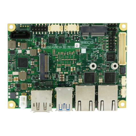
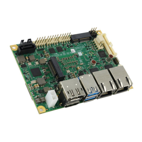
Seco SECOnITX-ION User manual

SECOnITX-ION
Single Board Computer with Intel®Celeron™T3100 or Intel®Atom™
N270 CPU and NVIDIA®MMP9 Embedded ION™Chipset on nanoITX
form factor
SECOnITX-ION
User Manual

SECOnITX-ION
User Manual - Rev. First Edition: 0.1 - Last Edition: 1.2 - Author: S.B. - Reviewed by G.M.
Copyright © 2011 SECO s.r.l.
SECOnITX-ION
pag. 2
REVISION HISTORY
Revision
Date
Note
Rif.
0.1
1st Sep 2010
First release
SB
0.2
5th Nov 2010
DVI connector’s image corrected (par. 3.3.7)
SB
1.0
4th Jan 2011
Connectors section updated
BIOS section updated
Appendix added
SB
1.1
25th Jan 2011
CN32 pinout corrected
SB
1.2
12th Jul 2011
Technical specification for LVDS and DVI outputs updated
Video Settings Utility section added
SB
All rights reserved. All information contained in this manual is confidential material and
property of SECO S.r.l.
Unauthorised use, duplication, modification or disclosure of the information to a third-party by any
means without prior consent of SECO S.r.l. is prohibited.
Every effort has been made to ensure the accuracy of this manual, however, SECO s.r.l. accepts
no responsibility for any inaccuracies, errors or omissions herein. SECO s.r.l. reserves the right to
change specifications without prior notice in order to supply the best product possible.
Most of the information found in BIOS SETUP Chapter has been extracted from the following
copyrighted American Megatrends, Inc documents:
•AMIBIOS8 Setup User’s Guide
The above mentioned documents are copyright© 2010 American Megatrends, Inc. All rights
reserved.
For more information on this and other SECO products, please visit our web-site at:
http://www.seco.it
describing the current problem.
SECO Srl - Via Calamandrei 91
52100 Arezzo –ITALY
Ph: +39 0575 26979 - Fax: +39 0575 350210
http://www.seco.it

SECOnITX-ION
User Manual - Rev. First Edition: 0.1 - Last Edition: 1.2 - Author: S.B. - Reviewed by G.M.
Copyright © 2011 SECO s.r.l.
SECOnITX-ION
pag. 3
INDEX
Chapter 1 INTRODUCTION ...................................................................................................5
1.1 WARRANTY............................................................................................................................................ 6
1.2 INFORMATION AND ASSISTANCE .............................................................................................................. 7
1.3 RMA NUMBER REQUEST......................................................................................................................... 7
1.4 SAFETY ................................................................................................................................................. 8
1.5 ELECTROSTATIC DISCHARGES................................................................................................................ 8
1.6 ROHS COMPLIANCE ............................................................................................................................... 8
Chapter 2 OVERVIEW ...........................................................................................................9
2.1 INTRODUCTION..................................................................................................................................... 10
2.2 TECHNICAL SPECIFICATIONS................................................................................................................. 11
2.3 ELECTRICAL SPECIFICATIONS................................................................................................................ 12
2.3.1 Power Button Connector.............................................................................................................. 12
2.3.2 Hard Disk Power.......................................................................................................................... 13
2.3.3 RTC Battery................................................................................................................................. 13
2.4 SUPPORTED OPERATING SYSTEMS....................................................................................................... 14
2.5 MECHANICAL SPECIFICATIONS .............................................................................................................. 15
2.6 HEATSINK............................................................................................................................................ 16
Chapter 3 CONNECTORS...................................................................................................17
3.1 CONNECTORS PLACEMENT ................................................................................................................... 18
3.2 CONNECTORS OVERVIEW ..................................................................................................................... 20
3.2.1 Connectors Overview .................................................................................................................. 20
3.3 CONNECTORS DESCRIPTION................................................................................................................. 21
3.3.1 Compact Flash socket ................................................................................................................. 21
3.3.2 S-ATA connectors........................................................................................................................ 22
3.3.3 Serial Port COM1......................................................................................................................... 22
3.3.4 PS/2 Keyboard Connector........................................................................................................... 23
3.3.5 FAN Connector............................................................................................................................ 23
3.3.6 Mini PCI Express Slot.................................................................................................................. 24
3.3.7 VIDEO OUTPUTS ....................................................................................................................... 25
3.3.7.3 LVDS Connector.......................................................................................................................... 26
3.3.7.4 LCD Power Pin Header ............................................................................................................... 26
3.3.7.5 HDMI Connector (optional).......................................................................................................... 27
3.3.8 Gigabit Ethernet Connector ......................................................................................................... 27
3.3.9 USB 2.0 connectors..................................................................................................................... 28
3.3.10 Internal USB header .................................................................................................................... 28
3.3.11 Audio Connectors ........................................................................................................................ 29
3.3.12 GPIO Connector .......................................................................................................................... 29
3.3.13 SM Bus Header............................................................................................................................ 30
3.3.14 SO-DIMM DDR3 Slot................................................................................................................... 30
Chapter 4 BIOS SETUP.......................................................................................................31
4.1 AMIBIOS UTILITY.............................................................................................................................. 32
4.2 MAIN SETUP MENU.......................................................................................................................... 32
4.2.1 System Time/System Date.......................................................................................................... 32
4.3 ADVANCED MENU ........................................................................................................................... 33
4.3.1 CPU Configuration Submenu ...................................................................................................... 33
4.3.2 IDE Configuration Submenu........................................................................................................ 34
4.3.3 ACPI Configuration Submenu...................................................................................................... 35
4.3.4 MPS Configuration Submenu...................................................................................................... 36
4.3.5 PCI Express Configuration Submenu.......................................................................................... 37
4.3.6 Smbios Configuration Submenu.................................................................................................. 37
4.3.7 Trusted Computing Submenu...................................................................................................... 38
4.3.8 USB Configuration Submenu....................................................................................................... 38
4.4 PCIPNPMENU................................................................................................................................... 39
4.5 BOOT MENU ..................................................................................................................................... 40

SECOnITX-ION
User Manual - Rev. First Edition: 0.1 - Last Edition: 1.2 - Author: S.B. - Reviewed by G.M.
Copyright © 2011 SECO s.r.l.
SECOnITX-ION
pag. 4
4.5.1 Boot Settings Configuration Submenu ........................................................................................ 40
4.6 SECURITY MENU ............................................................................................................................. 41
4.7 CHIPSET MENU................................................................................................................................ 42
4.7.1 Northbridge/MMP9-ION Configuration Submenu........................................................................ 42
4.7.2 Southbridge Configuration........................................................................................................... 44
4.7.3 Fan Control Options Submenu.................................................................................................... 46
4.8 EXIT MENU........................................................................................................................................ 47
4.9 VIDEO SETTINGS UTILITY............................................................................................................... 48
4.9.1 Panel Resolution.......................................................................................................................... 48
4.9.2 Panel Resolution.......................................................................................................................... 49
4.9.3 Color bit Mapping......................................................................................................................... 49
4.9.4 Wait time...................................................................................................................................... 49
Appendix A Application Notes.................................................................................................50
A.1 Microsoft®Windows®7 Installation Procedure for Intel®T3100 CPU....................51

SECOnITX-ION
User Manual - Rev. First Edition: 0.1 - Last Edition: 1.2 - Author: S.B. - Reviewed by G.M.
Copyright © 2011 SECO s.r.l.
SECOnITX-ION
pag. 5
Chapter 1 INTRODUCTION
Warranty
Information and assistance
RMA number request
Safety
Electrostatic Discharges
RoHS compliance

SECOnITX-ION
User Manual - Rev. First Edition: 0.1 - Last Edition: 1.2 - Author: S.B. - Reviewed by G.M.
Copyright © 2011 SECO s.r.l.
SECOnITX-ION
pag. 6
1.1 Warranty
This product is subject to Italian law D. Lgs 24/2002, acting European Directive 1999/44/CE on
arguments of sale and warranties to consumer.
The warranty for this product lasts 1 year
Under the warranty period the Supplier guarantees the buyer an assistance service for repairing,
replacing or credit of the item, at its own discretion.
Shipping costs regarding non-conforming items or items that need replacement, are to be paid by
the customer.
Items cannot be returned unless formerly authorized by the supplier.
The authorization is released after compiling the specific form available from the web-site
http://www.SECO.it (RMA Online). Authorization number for returning the item must be put both on
the packaging and on the documents brought with the items, that have to be not damaged, not
tampered, with all accessories in their original packaging.
Error analysis form identifying the fault type has to be compiled by the customer and has to be sent
in the packaging of the returned item.
If some of the above mentioned requirements for returning the item is not satisfied, item will be
shipped back and customer will have to pay for shipping costs.
The supplier, after a technical analysis, will verify if all the requirements for warranty service are
met. If warranty cannot be applied, he calculates the minimum cost of this initial analysis on the
item and the repairing costs. Costs for replaced components will be calculated aside.
Warning! All changes or modifications to the equipment not clearly approved by
SECO S.r.l. could impair equipment’s functionality and lead to the
expire of the warranty

SECOnITX-ION
User Manual - Rev. First Edition: 0.1 - Last Edition: 1.2 - Author: S.B. - Reviewed by G.M.
Copyright © 2011 SECO s.r.l.
SECOnITX-ION
pag. 7
1.2 Information and assistance
What do I have to do if the product is faulty?
SECO S.r.l. offers the following services:
SECO website: visit http://www.SECO.it to receive the last information on the product. In most
of the cases you can find useful information to resolve your problem.
SECO reseller: the reseller or agent can help you in determining the exact cause of the
problem and search the best solution for it.
SECO Help-Desk: contact by phone the SECO Technical Assistance.
A technician is at your disposal to understand the exact origin of the problem and suggest the right
solution.
ITALY Tel. (+39) 0575 340427
Fax (+39) 0575 340434
Repairing center: it is possible to send the faulty product to SECO Repairing Centre. In this
case, follow this procedure:
Returned items have to be provided with RMA Number. Items sent without RMA
number will be not accepted.
Returned items have to be packed in the appropriate manner. SECO is not responsible
for damages caused by accidental drop, improper usage, or customer neglects.
Note: We ask to prepare the following information before asking for technical assistance:
- Name and serial number of the product;
- Description of Customer’s peripheral connections;
- Description of Customer’s software (operative system, version, application software, etc.);
- A complete description of the problem;
- The exact words of every kind of error message received
1.3 RMA number request
To request a RMA number, please, visit SECO’s web-site. In the home-page select “RMA Online”
and follow the described procedure
You will receive an RMA Number within 1 working day (only for on-line RMA request).

SECOnITX-ION
User Manual - Rev. First Edition: 0.1 - Last Edition: 1.2 - Author: S.B. - Reviewed by G.M.
Copyright © 2011 SECO s.r.l.
SECOnITX-ION
pag. 8
1.4 Safety
SECOnITX-ION module uses only extremely-low voltages.
While handling the board, it is necessary to be careful in order to avoid any kind of risk or damages
to electronic components. Always switch the power off, and unplug the power supply unit, before
handling the board and/or connecting cables or other boards.
Don’t use metallic components, like paper clips, screws and similar, near the board, when this is
supplied, to avoid short circuits due to unwanted contacts with other components of the board.
Never connect the board to an external power supply unit or battery, if the board has become wet.
Make sure that all cables are correctly connected and are not damaged.
1.5 Electrostatic Discharges
SECOnITX-ION, like any other electronic product, is an electrostatic sensitive device and some
components on-board could be damaged by high voltages caused by static electricity.
So whenever handling a SECOnITX-ION board, take care to ground yourself through an anti-static
wrist strap. Placement of the board on an anti-static surface is also highly recommended.
1.6 RoHS compliance
SECOnITX-ION board is designed using RoHS compliant components and is manufactured on a
lead-free production line. It is therefore fully RoHS compliant.

SECOnITX-ION
User Manual - Rev. First Edition: 0.1 - Last Edition: 1.2 - Author: S.B. - Reviewed by G.M.
Copyright © 2011 SECO s.r.l.
SECOnITX-ION
pag. 9
Chapter 2 OVERVIEW
Introduction
Technical Specifications
Electrical specifications
Supported Operating Systems
Mechanical specifications
Heatsink

SECOnITX-ION
User Manual - Rev. First Edition: 0.1 - Last Edition: 1.2 - Author: S.B. - Reviewed by G.M.
Copyright © 2011 SECO s.r.l.
SECOnITX-ION
pag. 10
2.1 Introduction
SECOnITX-ION is a Single Board Computer (SBC) in nano-ITX form factor module, based on
Intel®Celeron®T3100, a Dual Core CPU running at 1,9GHz (800MHz FSB), with 1MB Cache L2,
64-bit Instruction Set.
Alternatively, the board can be supplied with Intel® Atom™ N270 CPU, a Single Core CPU running
at 1.6 GHz (533MHz FSB), with 512KB L2 Cache, Hyper Threading (HT) capabilities and 32-bit
Instruction Set.
The chipset of the board is formed by NVIDIA®ION™ MMP9 (embedded ION™) IC, that
implements all the functionalities of standard Chipsets, as well as a powerful 2D an 3D graphic
accelerator of GeForce9400 family, including 16 graphic cores that can be exploited at their
maximum using CUDA libraries, freely available from NVIDIA®Website. This feature gives the
board very high graphical performances, so that it can be used even for the most powerful 3D
applications.
Graphical capabilities of the Chipset allow one to drive directly two independent monitors, using
CRT, HDMI and LVDS or DVI interfaces (LVDS is available only in alternative to DVI interface).
NVIDIA®ION™ MMP9 manages also directly the access to memory, which is available on a single
SODIMM DDR3 memory module, with frequencies up to 1066MHz, with a capacity up to 4GB.
Other features controlled directly by NVIDIA MMP9 Embedded ION Chipset are 1 x miniPCI
Express, 2 x Serial ATA ports, 6 USB 2.0 ports (2 of them internally available on a pin header), 1
RS-232 Serial Port, PS/2 Keyboard, Real Time Clock and Watch Dog Timer.
Other features of the board are implemented using auxiliary controllers: for this reason, the board
can also offer one Gigabit Ethernet port, HD Audio interface, 8 x general Purpose I/O, Compact
Flash socket.
Optionally, onboard can also be installed a TPM device, ATMEL AT97SC3203, for computing of
RSA signatures in very short times and pseudo-random numbers generation, to be used both for
encryption keys generation and random number generation for normal software usage.
Please refer to following chapter for a complete list of all peripherals integrated and characteristics.
For thermal dissipation of heat generated, the board is supplied with a custom finned heatsink (with
or without fan). Please see specifications in related chapter.

SECOnITX-ION
User Manual - Rev. First Edition: 0.1 - Last Edition: 1.2 - Author: S.B. - Reviewed by G.M.
Copyright © 2011 SECO s.r.l.
SECOnITX-ION
pag. 11
2.2 Technical Specifications
CPU: Intel®Celeron®T3100 1,9GHz, 1MB L2 Cache, 800MHz FSB, Dual Core,
64-bit Instruction Set
Intel®Atom™N270 1.6 GHz, 512KB L2 Cache, 533MHz FSB Hyper
Threading (HT) capabilities, 32-bit Instruction Set
Chipset: NVIDIA®MMP9 Embedded Ion
DRAM: Up to 4GB DDR3 on a single SO-DIMM socket
Graphics: Integrated NVIDIA®GeForce 9400 Graphic Controller
16 independent graphic/computational cores, usable at best using CUDA
free libraries
Integrated Graphics Shared Memory up to 512MB
Dual independent display support
Optional CRT connector, with resolution up to 1920x1440 @ 75Hz
(QXGA)
Optional HDMI connector, with resolution up to 1920x1200
Optional LVDS or DVI connector, with resolution up to 1600 x 1200
Full HD support (both 1080i and 1080p)
Supports DirectX10 Shader Model 4.0 and OpenGL rel. 2.1
Expansion slots: miniPCI-E socket
1 x GPI/O Pin Header
SM Bus Pin Heaader
USB: 6 x USB 2.0 (2 of them available only on internal pin header)
Ethernet: Gigabit Ethernet controller, Realtek®RTL8211CL
Mass Storage: 2 x S-ATA connectors
Compact Flash Socket
AUDIO: Dual jack for HD audio
Line In connector
Serial Ports: 1 x RS-232 port, RS-232/RS-485 configurable
PS/2 Keyboard internal Pin Header
Watch Dog Timer
Optional TPM device, ATMEL AT97SC3203
Power Management, ACPI 2.0 compliant
+12VDC Power supply
Operating Temperature: 0°C ÷ +70°C with dedicated finned heatsink
Dimensions: 120 x 120 mm (4.72” x 4.72”).

SECOnITX-ION
User Manual - Rev. First Edition: 0.1 - Last Edition: 1.2 - Author: S.B. - Reviewed by G.M.
Copyright © 2011 SECO s.r.l.
SECOnITX-ION
pag. 12
2.3 Electrical specifications
SECOnITX-ION board needs to be supplied using an external +12VDC Power Supply, working in
AT mode.
Power Connector is type Molex Mini-Fit Jr. connector, p/n 39-28-1043, or equivalent, with the pin-
out indicated in the following table.
Power connector –CN32
Pin
Signal
Pin
Signal
1
GND
2
GND
3
+12VDC
4
+12VDC
2.3.1 Power Button Connector
SECOnITX-ION board is able to work in ATX mode, following ACPI specifications for Power
Management.
For this reason, on board there is a connector carrying signals for the Power Button (to be used to
put the system in a Soft Off State, or awake from it), for Reset Button, and for an eventual intruder
switch (managed directly by MMP9 Embedded ION Chipset).
There is also a Wake_Enable Input to indicate the occurrence of a Power Management Event, and
a PS_ON signal to be used for management of ATX Power Supply
All signals are carried on a 8 pin, p2 mm, single row connector, type MOLEX 89400-0810 or
equivalent.
Power Button Connector –CNX4
Pin
Signal
1
+5VSB
2
GND
3
PS_ON
4
POWER_BUTTON#
5
INTRUDER#
6
WAKE_ENABLE
7
RESET_BUTTON#
8
GND

SECOnITX-ION
User Manual - Rev. First Edition: 0.1 - Last Edition: 1.2 - Author: S.B. - Reviewed by G.M.
Copyright © 2011 SECO s.r.l.
SECOnITX-ION
pag. 13
2.3.2 Hard Disk Power
It is possible to give power supply to an external Hard Disk by connecting it directly to the board,
and not to an additional Power Supply Unit, therefore reducing the need of a PSU able to manage
both the board and the Hard Disk Drive.
For connection, there is a 4-pin connector type TKP p/n 4040I-04, with pinout written in the
following table. The connector is standard for HDD.
Hard Disk Power connector –CNX2
Pin
Signal
Pin
Signal
1
+12VDC
3
GND
2
GND
4
+5VDC
WARNING: This connector has to used exclusively to give Power Supply to external
Hard Disks (so, as a power output of the board), it must not absolutely be used to give
Power Supply (as a power input) to the board.
2.3.3 RTC Battery
For the occurrences when the board is not powered with an external power supply, on board there
is a vertical battery holder, for the use of standard coin battery, type CR2032, with a nominal
capacity of 220mAh, to supply, with a 3V voltage, the Real Time Clock and CMOS memory
mounted onboard
It is also possible to connect an external 3.3V Battery, using dedicated connector CNX6, that is a
2-pin header P 2.54 mm, with following pinout:
External Battery Pin Header –CNX6
Pin
Signal
1
EXT_VBAT
2
GND
It is possible to reset CMOS data using jumper JP3, which is a standard 3-pin header p2.54 mm,
with following usage:
JP3 position
Meaning
1-2
CMOS data reset
2-3
Normal working
Current-limiting devices have been implemented to fulfill EN60950 requirements.
Batteries should only be replaced with devices of the same type. Always check the orientation
before inserting and make sure that they are aligned correctly and are not damaged or leaking.
Never allow the batteries to become short-circuited during handling.
CAUTION: handling batteries incorrectly or with not-approved devices may present a risk of fire or
explosion.
Batteries supplied with SECOnITX-ION board are compliant to requirements of European Directive
2006/66/EC regarding batteries and accumulators. When putting out of order SECOnITX-ION
board, remove the batteries from the board in order to collect and dispose them according to the
requirement of the same European Directive above mentioned. Even when replacing the batteries,
the disposal has to be made according to these requirements.

SECOnITX-ION
User Manual - Rev. First Edition: 0.1 - Last Edition: 1.2 - Author: S.B. - Reviewed by G.M.
Copyright © 2011 SECO s.r.l.
SECOnITX-ION
pag. 14
2.4 Supported Operating Systems
SECOnITX-ION supports the following operating systems:
Microsoft®Windows®7 (see Appendix A)
Microsoft®Windows®Vista
Microsoft®Windows®XP/2000
Microsoft®Windows®XP Embedded
Microsoft®Windows®CE 5.0 / 6.0
Linux

SECOnITX-ION
User Manual - Rev. First Edition: 0.1 - Last Edition: 1.2 - Author: S.B. - Reviewed by G.M.
Copyright © 2011 SECO s.r.l.
SECOnITX-ION
pag. 15
2.5 Mechanical specifications
According to nanoITX form factor, board dimensions are: 120 x 120 mm (4.72” x 4.72”).
The printed circuit of the board is made of ten layers, some of them are ground planes, for
disturbance rejection.

SECOnITX-ION
User Manual - Rev. First Edition: 0.1 - Last Edition: 1.2 - Author: S.B. - Reviewed by G.M.
Copyright © 2011 SECO s.r.l.
SECOnITX-ION
pag. 16
2.6 Heatsink
For thermal dissipation of SECOnITX-ION board, a custom finned heatsink (directly provided by
SECO) is necessary. This heatsink can be supplied with our without fan: best board’s
performances are reached using the heatsink with fan.
Here following is displayed the heatsink designed explicitly for the board.

SECOnITX-ION
User Manual - Rev. First Edition: 0.1 - Last Edition: 1.2 - Author: S.B. - Reviewed by G.M.
Copyright © 2011 SECO s.r.l.
SECOnITX-ION
pag. 17
Chapter 3 CONNECTORS
Connectors placement
Connectors overview
Connectors Description

SECOnITX-ION
User Manual - Rev. First Edition: 0.1 - Last Edition: 1.2 - Author: S.B. - Reviewed by G.M.
Copyright © 2011 SECO s.r.l.
SECOnITX-ION
pag. 18
3.1 Connectors placement
On SECOnITX-ION carrier board, there are several connectors. Some of them are standard
connectors, like CRT, DVI, USB, Ethernet, Audio, HDMI, and are placed on the same side of the
board, so that they can be placed on a panel of an eventual containing box. Please notice that all
video connectors are optional, so that final configuration can be different from that shown in the
next picture.
HDD power
connector
Battery Holder
S-ATA 0
connector
LVDS
connector
Line-IN
connector
SODIMM
DDR3 Slot
Power button
connector
Gigabit
Ethernet
Dual Audio
Jack
USB 0-1 + 2-3
Connectors
VGA / DVI
connector
PS/2 keyboard
HDMI Pin
Header
GPIO
connector
LCD Power
Pin Header
COM1
Connector
RS-485
Connector
CPU FAN
connector
S-ATA 1
connector
USB 4-5 Pin
Header
POWER
connector
Ext. Battery
Pin Header
SM Bus Pin
Header
Jumper JP3
MMP9 FAN
connector

SECOnITX-ION
User Manual - Rev. First Edition: 0.1 - Last Edition: 1.2 - Author: S.B. - Reviewed by G.M.
Copyright © 2011 SECO s.r.l.
SECOnITX-ION
pag. 19
Compact
Flash Socket
MiniPCI
Express slot

SECOnITX-ION
User Manual - Rev. First Edition: 0.1 - Last Edition: 1.2 - Author: S.B. - Reviewed by G.M.
Copyright © 2011 SECO s.r.l.
SECOnITX-ION
pag. 20
3.2 Connectors overview
3.2.1 Connectors Overview
Name
Description
Name
Description
CN3
S-ATA 0
CN40
DVI
CN4
S-ATA 1
CN41
VGA
CN6
Compact flash
CNX2
Hard Disk Power
CN10
mini PCI Express slot
CNX3
PS/2 Keyboard
CN11
COM1
CNX4
Power Button
CN18
Battery Holder
CNX5
GPIO
CN19
Dual Audio Jack
CNX6
External Battery
CN20
LCD Power
CNX7
SM Bus
CN22
LVDS
CNX9
Internal Line-In
CN32
Power In
J1
CPU FAN
CN34
RS-485
J2
MMP9 FAN
CN35
Gigabit Ethernet
J3
USB 4-5
CN36
USB 0-1
J8
DDR-3 SODIMM slot
CN37
USB 2-3
J10
HDMI Header
Table of contents
Other Seco Single Board Computer manuals
Seco
Seco SYS-B68-IPC Quick start guide
Seco
Seco TANARO User manual
Seco
Seco SBC-C43 User manual
Seco
Seco THEMIS User manual
Seco
Seco SBC-984 User manual

Seco
Seco EASYSHRINK EVO User manual
Seco
Seco SYS-B68-IGW Quick start guide
Seco
Seco SBC-C23 User manual
Seco
Seco SYS-C31-DMV Instructions for use
Seco
Seco SBC-C61 User manual
Popular Single Board Computer manuals by other brands
Actis
Actis VSBC-6872 Series user guide

Motorola
Motorola MCPN750A Installation and use
StarFive
StarFive VisionFive 2 quick start guide
Motorola
Motorola MVME2400 Series Installation and user manual
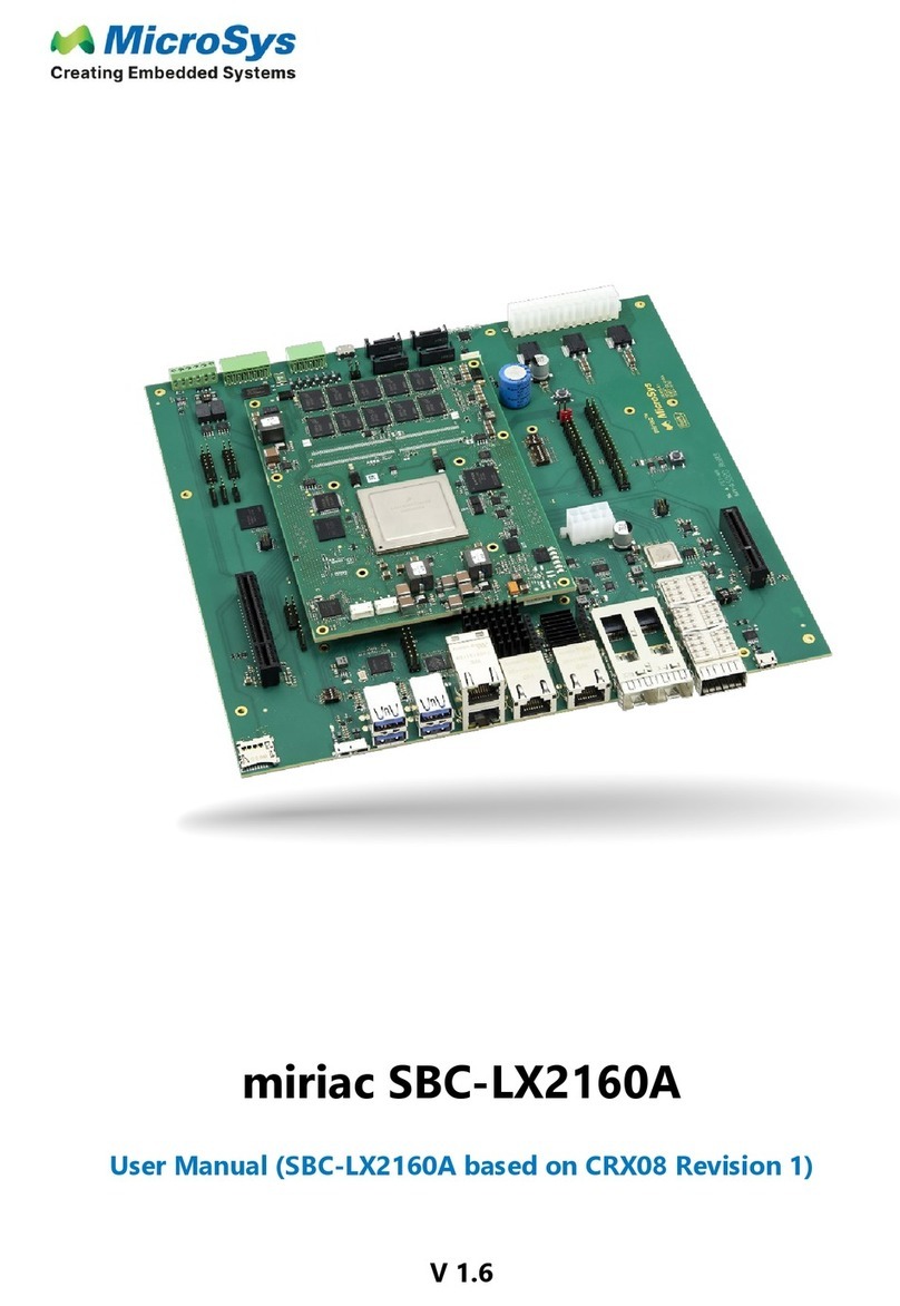
MicroSys
MicroSys miriac SBC-LX2160A user manual

ADLINK Technology
ADLINK Technology ReadyBoard 850 user manual
