SECOLink P16 User manual

SAFETY WARNINGS
Please act according to your local rules and do not dispose of your unusable alarm system or its components with other household waste. This product
utilizationinEUiscoveredbyEuropeanDirective 2002/96/EC.
The device must be installed in a place with limited access.
Thedevice mustbe connectedtoACpower supplywith ProtectiveEarthing. Cablecolors andpurpose: Phaseor Liveline (L)- blackor browncable, Neutral
line(N) -blue cable,Protective Earth line(PE) -greencable withavertical yellowstripe.Please useonlydouble isolatedcables with across-sectional area
2
ofnolessthan0,75mm forthe230Vpowersupply.
Thedeviceusestwopowersupplies:mainandback-up.
2V,7Ah/20HRcapacity,rechargeablehermeticallysealedLead-Acidbattery.
Mainpowersupply:a power transformer with:
-primarywinding:~230V,50Hz;
-secondarywinding:~20V,1.5A,50Hz.
Back-uppowersupply:1
SECOLINKintruderalarmsystem iscompliantwith EN60950-1safetyrequirements.
PowersuppliesdescribedabovemustcomplywiththeEN60950-1safetyrequirements.
Alldevicesconnectedtotheintruderalarmsystem(sirens,detectors,computerforprogramming,andetc.)mustcomplywithEN60950-1safetyrequirements.
Additional automatic Two-Pole Circuit Breaker should be installed inAC electric power circuit in order to protect against over-current, short circuits, and earthing
faults.
Thecircuitbreakercontactgapshouldbenolessthan3mm,protectivecircuitbreaker currentmustbe ina0,5A-2A range.
Thecircuitbreakershouldbeplacedclosetothesystem'shousingandshouldbeeasilyaccessed.
Beforeperforminganyworkofinstallationorservicealwaysdisconnectthedevicefrompowersuppliesinsequenceasdescribedbelow:
- cutoffthe230VACpowerlinebyturningofftheautomaticTwo-poleCircuitBreaker;
- disconnectthe12Vback-upbatterybyremovingthefemalebatteryplugfrommalesocketBAT.
Two-poleCircuit-Beakerinstallationonflexiblecablesisforbidden.
Generalsafetyrequirements:
-donottouchanypartofthemainpowersupplyundervoltagesuchasatransformer,fuseblock,orconnectionwires;
-itisforbiddentoperformanydeviceinstallationorserviceworkduringlightning;
-usebatteriesaspermanufacturer’srecommendations.Theuseofimproperbatterytypemaycauseanexplosion;
-batteryreplacement:makesurethatbatteryterminalsareisolated;batteryterminalsshort-wiring maycauseanexplosion.
It is not recommended to connect the device to a fully discharged battery. To avoid system malfunction use an adequate charger to charge a new or
dischargedbatterybeforeconnectingittothedevice.
Inoperativeorexpiredbatteriesshouldberecycledaccordingtothelocalrulesor EUdirectives 2006/66/EC and 93/86/EEC.
Collectionandseparateutilizationofwastebatteryismandatory!
Connectiontothemainsupplymustbemadeasperlocalauthorityrulesandregulations.
Theendofastrandedconductorshallnotbeconsolidatedbysoft-solderingandinsulatedpinsshouldbeusedinstead.Insulatedpinsneedtobeconnectedinaproper
mannertoremainmechanicallyefficient.
The PSTN communicator's PSTP terminals TIP, RING, T-1, R-1 should be connected to analog PSTN line. Connection to digital ISDN line may cause device
damage.
Deviceinstallationandserviceshould beperformed bytrained personnelwithsufficientknowledgeabout thedevice andgeneral safetyrequirementstoworkwithlow
voltage (up to 1000V)AC power lines. In case of a device malfunction, repair works can only be performed by qualified personnel. If the system is malfunctioning, the
endusershouldinformqualified personnelassoonaspossible.Theuserdoesnothavepermisiontorepairthesystem.
Alarmsystemmodules comewith abuilt-inLED indicator. LEDblinkswhen themoduleis poweredup. Pressanykey onthekeypadtocheck ifthesystem ispowered
upornot.Ifthesystemwaspoweredup,thekeypadbacklightwilllastfor30seconds.
LAN800 and VIDNET are designed to be used together with a router which is placed in the same room or premises. It’s prohibited to connect LAN800 or VIDNET
directlyto WideAreaNetwork(MAN,WAN)orbuildingITinfrastructurecables.
Power supply distribution board
Automatic two-pole circuit
breaker
L N
N
L
Cable from a power
distribution board
Power cable to the
alarm system
Cabinet of the alarm system (device)
Picture 1. Automatic two-pole circuit breaker and a power cable wiring diagram
Page 1
General information
ControlpanelsP16,P32,andP64performallnecessaryfunctionstoprotectapartments,offices,homes,orvillas.ItincludesallPASseriescapabilitiesandcomeswith
additional functions. The device is equipped with a reliable pulse-type power supply measurement, powerful siren control, failing battery disconnection, built-in
wirelessmoduleEXT116SVM, 2 wiresmoke detector controlcircuitry,and an optiontosecurely connect exchangeablecommunicators. It isdesignedto beoperated
by keypads connected with a four-wire cable and is capable of being programmed by means of computer and software MASCAD in MS Window environment. More
information can be found at intruder alarm systems manufacturer's, Kodinis Raktas UAB, website http://www.secolink.eu/en/products/control-panels. Manufacturer
declaresthatproductsP16,P32,P64 complywithessentialEUdirectivesandEUstandardsEN50131-1,Grade1,EnvironmentalClassII;EN50131-3,EN50131-6.
Intruder alarm system Wiring manual
Control Panels P16, P32, P64

DAT
COM
+12V
CLK
3.15A
P16
P32
P64
COM
+BELL
DAT
+AUX
CLK
COM
-PGM
+PGM
COM
Z2
Z6 +AUX Z7 COM Z8
Z1
ANT
R-1
T-1
RING
TIP
PSTP
For correct operation P series control panels P16,
P32 and P64 (abbreviation: Pxx) need one 12V 7Ah
rechargeable battery. The battery is used as a back-
uppower supplyincaseofatemporaryAC loss.This
battery is also used when an alarm system
consumes more power than control panel can
supply. Excessive consumption may happen when
the system activates a siren or a radio transmitter.
Usually activation lasts only a few minutes to not
dischargethebattery.
Installation of control panel
+BELL
COM
Picture 2. Wiring of the power supply, PSTN line,and a siren without the
battery
If an installation of a siren with back-up battery is done
using 2 wires (picture 4), then an installer needs to make
changesas showntothe right.This typeofa sirenuses a
back-up battery to sound an alarm when power supply
line (+BELL) does not provide power from the control
panel. Use Inversion of Status PGM attribute to program
thesystemfor this operation. Programming sequenceis
describedontheright.
Note: in most templates +BELL is set for sirens with no
battery (picture 2). To use a siren with a back-up battery
(picture3)youneedtochange +BELL(O01)definitionto
Powersupply.Definition changingsequenceisshownon
theright.
If control panel’s PGM output -PGM direct connection to siren
triggering input S does not ensure a stable siren activation, please
connect the pull-up resistor (3-15 kOhm) between the +Bell and -
PGMasshowninthepicturebelow.
+BELL
COM
-PGM
10kΩ
S
power supply
negative control
power supply
Picture 3. Installation of a siren with a back-up battery using 3 wires
SECOLINK security systems are supplied to customers with a pre-installed template
inthekeypad memory.Thetemplateisasetofmostfrequentlyused systemsettings.
During First start procedure keypad sends these settings to other modules. When
Firststartiscompletedthesystemwillbesetto1partitionand 8 zones:
Z1ispresettobeusedwithanentrydoormagneticcontact;
Z2- with PIRmotiondetectorinentry/exit path;
Z3,Z4- forPIRdetectorswiring;
Z5- withasmokedetector;
Z6-forcabinettamperswitchwiring;
PGMoutputs:
+BELL(O01)ispresetinthetemplatetocontrolasirenwithnobattery;
-PGM (O02) is preset to make an activation (makes “minus”) of a siren with a back-
upbattery;
+PGM(O03)ispresettomake+12Vpower supply forsmokedetectors.
Template. Siren output programming
SECOLINK security systems may have different
templates for different countries. Check keypad's sticker
for a country prefix or the pre-installed template code.
Example: KM24_MY
Attention!
Do not cover ventilation
holes of the cabinet!
Mounting modules in the
cabinet
Use a tamper switch to protect the control panel
Securing power cable
to the cabinet
Zones (see "Zone wiring")
+PGM
COM
+12V CLKDAT COM
CLK
DAT
+AUX
Module
-PGM
Main Protective
Earthing terminal
Protective Earth
wire PE
Analog PSTN
line
TIP RING T-1 R-1
Serial port SERIAL (see "Wiring of system modules”)
+AUX Z3 COM Z4 -Z5F +Z5F
COM
+BELL
-PGM
Z3
Z4
-Z5F
+Z5F
Z6
+AUX
Z7
COM
Z8
COM
+AUX
20VAC COM -PGM +PGM COM CLK DAT +AUX Z1 COM Z2+BELL
20 VAC
20 VAC
20VAC COM -PGM+BELL
Picture 4. Installation of a siren with a back-up battery using 2 wires.
S
power supply
positive control / power supply
Note: check siren wiring manual provided by the manufacturer.
Switchesorjumperscanbeused tosetupthistypeofthesiren.
+BELL
COM
COM
+BELL
-PGM
20VAC COM -PGM+BELL
20 VAC
Leave minimum 10 cm of free space
between the ventilation hole and any
other surface. Increase in
temperature of control panel can
reduce the maximum current on
+AUX and PGM outputs: +BELL,
+PGM.
BydefaultcontrolpanelzoneZ6issetfordetectionofalarmsystem'scabinet
opening. Opening the cabinet when the system is disarmed will create a
trouble event or will trigger an alarm if the system is armed. When cabinet’s
tamper is unused, input Z6 can be set as a normal zone. Tamper disabling
sequenceisdescribedinthepicturebelowontheright.
Plastic box
Board
Pxx
Screw
Z6
AUX
Z7
COM
Z8
+Z5F
+Z5F Z6 +AUX Z7 COM Z8
SERIAL port
+13,8 V
COM
RX-DAT
TX-CLK
Use a plastic component to fasten
apowercabletothecabinet.
Boardsofcontrolpanelsandmodules
have to be fastened in a plastic
cabinet by using screws. Module's
mounting holes should correspond to
cabinet'srearwall holes.
Attention!Short-time current
consumed by radio transmitter
should not exceed 3A. Control
panel supplies current to this
connector with partial electronic
short-circuit protection. PCB
damage is possible in case of a
long-termhighcurrent.
Page 2
11
11
11
ServiceModeServiceMode
SystemSetupSystemSetup
ModulesModules
SystemSetupSystemSetup
ModulesModules
ModulesettingsModulesettings
M00 ControlpanelM00 Controlpanel
UsemoduletamperUsemoduletamper No
55
11
ServiceModeServiceMode
SystemSetupSystemSetup
O01 PowersupplyO01 Powersupply
DefinitionDefinition PowerSupply
33
44
SystemSetupSystemSetup
PGMoutputsPGMoutputs
11
ServiceModeServiceMode
SystemSetupSystemSetup
O01 PowersupplyO01 Powersupply
Inversion of statusInversion of status Yes
77
44
SystemSetupSystemSetup
PGMoutputsPGMoutputs
CAS6
Tamper switch
Intruder alarm system Wiring manual
Control Panels P16, P32, P64
Power supply
distribution board
AC power transformer:
Primary winding: 230V AC 50Hz
Secondary winding: 20V AC 50Hz
~~
12V battery
7Ah/20HR
Black
Red
Live
wire
L
Neutral
wire
N
Protective
Earth wire
PE
Main Protective
Earthing terminal
Fuse
250mA

Maximum battery charging current: 0,35A
Module disconnect battery when its
voltage is less than: 9,5V
Black
Red
12V battery
7Ah/20HR
3.15A
COM
+BELL
20VAC COM -PGM+BELL
System start-up with no 230V AC power
Non-volatile memory
Connect 12V battery to P
series control panel by using a
BAT connector. Use the
jumpertoclosetheshownpins
for 1 second.The system will
start operating; however, AC
losstroublewillbeindicated.
Jumper
Maximum current out of +AUX:
Maximum battery charging current:
Low battery voltage threshold:
1,5 A
2A
+1 A
+0,35 A
10,5 V
Maximum load ratings and electrical characteristics
of P series control panels
Maximum current out of +BELL:
Maximum current out of +PGM for P16:
Maximum current out of +PGM for P32, P64:
+2,0 A
+0,5 A
+0,9 A
Control panel disconnect battery when it’s voltage is less than: 9,5 V
Minimum AC voltage on 20 VAC:
Note: with ~16 V on 20 VAC max DC current generated by
control panel power supply is 0,7A.
Maximum current of afast blowing fuse used in battery circuit:
~16 V
3,15 A
Maximum AC voltage on :
Note: higher than V voltage can damage control panel
20 VAC
~22 .
Maximum voltage on +AUX, +BELL, +PGM outputs:
Minimum voltage on +AUX, +BELL, +PGM outputs:
~22 V
+13,9 V
+12,0 V
Max current of aslow blowing fuse used in primary AC circuit:
Maximum AC power consumption:250 mA
240 mA
Maximum long term output current of P16 control panel:
(I + I + I + I 1,5 A )
+AUX +BELL +PGM BAT. CHARGE
Maximum long term output current of P32, P64 control panel:
(I + I + I + I 2 A )
+AUX +BELL +PGM BAT. CHARGE Service mode is now enabled and service PIN is restored to 0000. To reset user
PINfollowthesteps:
donotblockservice bypressingENT;
pressarrowkeytonavigateinthemenu;
go to: Main Menu/Settings/Users/Edit Users/ enter 0000 /Reset PIN to
default/YES
Restoring service PIN to default value
Electrical characteristics and additional information
Wire
Maximum current into -PGM: -0,3A
Torestoredefaultvalue(0000)forservicePIN,followthesesteps:
disconnectcontrolpanelfrom20VACpowersupply;
disconnectcontrolpanelfromback-upbattery;
useawiretoshort-circuitthe-PGMandzoneZ1;
connectcontrolpanelto20VACpowersupply.
Control panel has non-volatile memory to store all parameters, event log,and the
lastcontrolpanelstatus.Systemstatusreturnsto thesamestatusasitwasbefore
thepowersupplywasdisconnected.
Keypad mounting
Keypad
Useonly self-tappingscrewswithaflat (countersunk)
head(3x30PH)tomountkeypad’splasticonthewall.
Make sure the screw is fastened completely and its
head is hidden in the plastic. Other shapes of screws
thatarenotcompletelyscrewedin,maytouch keypad
electronicsandcause damageofkeypad.
COM
+BELL
DAT
+AUX
Z1
COM
Z2
CLK
COM
-PGM
+PGM
20 VAC
20 VAC
Maximum long term current out of PWR20:
Maximum current out of +AUX:
2,0A
+1A
Maximum load ratings and electrical
characteristics of PWR20
Maximum current out of +BELL:
Maximum current into -PGM1:+2A
-0,05A
Wiring of modules in large or high security level system
12V battery
7Ah/20HR
Black
Red
Outdoor siren's safe wiring
Use a transformer, other than a control panel, and a
rechargeable 12V 7Ah battery to power up PWR20. If
an alarm system includes PWR20, it is recommended
to wire an outdoor siren to the PWR20 terminals
+BELL, -PGM1, (-PGM2), and COM same as shown
onpage2.Failureofsiren’sinternalbatteryorthesiren
itself will not affect the performance of an alarm
system.
PWR20 – power supply module
with a bus repeater
Repetition of the system bus (KRbus) is a perfect
solution when some system modules (PROX8,
EXTx16)are placedoutsidethepremises orinanarea
thatisnotprotectedbydetectors.Itisrecommendedto
wire all outside proximity readers or keypads located
near the entry door to the repeated (by PWR20) bus.
An attempt to make a short circuit on the outside
module will make no affect to system’s performance.
PWR20 will detect the short circuit on repeated bus
and will disconnect it from the main bus. Terminals
CLK-I and DAT-I are inputs for the main bus, terminals
CLK-OandDAT-O areoutputsof the repeated bus.To
supply power to modules, PWR20 output +AUX must
beused.
Module address LED
Low battery indicator
Battery charging on
Overload of +BELL or + AUX.
X1
BAT
OVL
CHG
LOW
MOD
PWR20
3.15A
DAT-O
CLK-O
COM
+12V
+12VCLK COMDAT
COM
DAT
+12V
CLK
DAT from Pxx
CLK from Pxx
COM from Pxx
+BELL
COM
-PGM1
TMP
COM
+AUX
CLK-I
CLK-O
DAT-I
DAT-O
20 VAC
DAT-O
CLK-O
COM
+12V
+12VCLK COMDAT
COM
DAT
+12V
CLK
Module
Live
wire
L
Neutral
wire
N
Protective
Earth wire
PE
Power supply
distribution board
Main Protective
Earthing terminal
Fuse
250mA
AC power transformer:
Primary winding: 230V AC 50Hz
Secondary winding: 20V AC 50Hz
~~
(I + I + I 2 A )
+AUX +BELL BAT. CHARGE
Page 3
+BELL
~20VAC COM-PGM1TMP COM +AUXCLK-ICLK-O
DAT-IDAT-O
Live
wire
L
Neutral
wire
N
Protective
Earth wire
PE
Main Protective
Earthing terminal Fuse
250mA
20VAC COM -PGM +PGM COM CLK DAT +AUX Z1 COM Z2+BELL
-10°C to +55°C
12 years
Operating temperature
Operating temperature range:
Note: ambient temperature over 40 may reduce life expectancy.°C
Note: poor ventilation of the cabinet increasesambient temperature.
Calculated life expectancy at 40 ambient temperature:
for °C
P16, P32, P64 control panels:
Intruder alarm system Wiring manual
Control Panels P16, P32, P64

3.15A
P16
P32
P64
COM
+BELL
DAT
CLK
COM
-PGM
+PGM
Wiring of system modules
KM24, KM24A, KM24G
KM20B, KM20BT
COM
+12V
+12V
COM
CLK
DAT
Z2
Z1
DAT
CLK
COM
+AUX
CLKDAT
+12VCOM
+12V Z1
Z2 COM
KRbus
EXM800
Z1 COM Z2K7 Z3K6 Z4K5 Z5K4
COM
Z1
COM
Z2/K7
Z3/K6
COM
Z4/K5
Z5/K4
DAT
COM
CLK
+12V
Z6K3 Z7K2 Z8K1
COM COM +AUX
COM
Z6/K3
Z7/K2
COM
Z8/K1
+AUX
Ethernet cable
COM CLK DAT+12V
LAN800
+12V
COM
CLK
DAT
+12VCOM CLK DAT
20VAC COM -PGM +PGM COM CLK DAT +AUX Z1 COM Z2 +AUX Z3 COM Z4 -Z5F +Z5F Z6 +AUX Z7 COM Z8+BELL
ANT
OPENOPEN
LOCKLOCK
GSVU
+AUX
+AUX
Z4
-Z5F
+Z5F
Z6
+AUX
Z7
COM
Z8
COM
Z3
COM
Z2
Z1
Z2/PGM
Z1
+12V
COM
CLK
DAT
COM
CLK
DAT
+12V
Z1
PGM
Z2
+AUX
COM
CLK
DAT
20 VAC
RING TIP
Not used
PROX8
+12V
COM
CLK
DAT
Modules compatibility with control panels Pxx
KM20B, KM20BT
Module Compatible (firmw.: v.5.030 and +) Not compatible
KM24, KM24A Compatible (firmw.: v.2.051 and +) Not compatible
KM24G Compatible (firmw.: v.3.009 and +)
PROX8 Limited compatibility (firmw.: v.0.10)
Only first 31 users will be able to control the system. Only first 32
zones will be monitored by PROX8 LEDs.
EXM800 Compatible (firmw.: all versions)
Compatible (firmw.: all versions)
Compatible (firmw.: all versions)
Compatible (firmw.: all versions)
Compatible (firmw.: all versions)
Compatible (firmw.: all versions)
Compatible (firmw.: all versions)
EXM3F
RCM800WL
EXT016, EXT216
EXT116S
PWR20
GSVU
GSV6, GSV6T,
GSV6U Compatible (firmw.: from v.1.025)
It is recommended to use GSVUmodule with P series control
panels. GSV6x module is only useful
when it is necessary to install module outside the cabinet.
LAN800
VIDNET Compatible (firmw.: from v.1.42)
Compatible (firmw.: all versions)
P16 P32 P64
BAT
CLK DAT +AUX Z1 COM Z2 +AUX Z3 COM Z4 -Z5F +Z5F Z6 +AUX Z7 COM Z820VAC COM -PGM +PGM+BELL COM
OPENOPEN
LOCKLOCK
CAM2 CAM3CAM4 COM COM COMCAM1 COM
CAM1 CAM2 CAM3 CAM4
P16
P32
P64
VIDNET
Control panels Pxx are designed in the way, that most commonly used modules can be directly plugged-on to the panel board (GSM module GSVU, video module
VIDNET).Allothermodulesthatdonothaveadirectinterfacewiththepanelmustbeconnectedtodatabus-KRbus.
Page 4
Intruder alarm system Wiring manual
Control Panels P16, P32, P64

Wiring of zones
Normally closed contact
(NC) Normally closed contact
with one resistor
(NC/EOL)
Normally closed contact
with two resistors
(NC/DEOL)
Normally open contact
(NO)Normally open contact
with one resistor
(NO/EOL)
Normally open contact
with two resistors
(NO/DEOL)
Wiring of single zones
Wiring of double zones
Detector
Control panel or
module Control panel or
module Control panel or
module Control panel or
module Control panel or
module Control panel or
module
+AUX
COM
Z1
COM
Tamper
Z2
Control
panel
+AUX
COM Z2
Detector
Detector
Z1
Cable
Cable
+AUX
COM
Detector
+AUX
COM
Z1
Cable
EXM800
+AUX
COM
Z1
Z2
+AUX
COM Z2
Detector
Detector
Z1
Cable
Cable
+AUX
COM
Detector
EXM800
ATTENTION! Avoid power supply loops
1kΩ620Ω
Control panel
+AUX
COM
Z1
COM
Detector A
T1
T2
NC*
C
Tamper Detector B
T1
T2
NC*
C
Tamper
300Ω
Detector A
Detector B
* - Detector contact must be NC or NO.
Control panel
Correct wiring
Wrong wiring
1kΩ
+AUX
COM
Z1
COM
Tamper
Detector
1kΩ
+AUX
COM
Z1
COM
Tamper
Detector
+AUX
COM
Z1
COM
Tamper
Detector
+AUX
COM
Z1
COM
Tamper
Detector
+AUX
COM
Z1
COM
Tamper
Detector
Wiring samples
Wiring of a 2-wire smoke detector
Detector
Control
panel
-Z5F
+Z5F
NO Note: smoke detectors, produced
by different manufacturers, may
have a different terminals layout.
For more information
’check
detectorwiringmanualprovidedby
the manufacturer.
Terminals of smoke detector
To -Z5F
To +Z5F
It is recommended to use diode to
supressvoltage surgesonrelay.
Wiring of relays
Smoke detectors can be triggered by dust. Therefore, to prevent
false alarms, it is recommended to verify the fire alarm. For
verification,theusermustactivatesystemsettingslistedbelow.
Zonesettings:
Zoneaddress:00_5(controlpanelzoneterminals-Z5F,+Z5F);
Zonelooptype:NO/EOL;
Zonedefinition:24hsmoke;
Attributeassignedtoazone:Fireverification;
Resettimemustbeset;
Systemtimessettings:
Detectorsettlingtimemustbeset;
Fireverificationtimemustbeset;
Operation: In order to check a triggered fire detector, detector's
powersupply hastobe turnedoffand turnedonagain. Thesystem
turnsthe-Z5FoffforaReset time.Whenthe resettimeexpires,the
system turns the -Z5F on again and waits for the detector to settle
(Detector settling time). After that, the system checks the detector
again for a time period set in the menu under the Fire verification
time setting. If the detector is triggered again, then this means that
thealarmreallyoccured.
Control panel or
module
+AUX
-PGM
Control panel or
module
+PGM
COM
T1
T2
NC
C
NO
NO
NO
Control
panel
2,2kΩ
T1
T2
NC
C
T1
T2
NC
C
T1
T2
C
T1
T2
C
T1
T2
C
+AUX COM Z1 COM+AUX COM Z1 COM
12V CT2 NCT1 12V CT2 NCT1
1kΩ1kΩ1kΩ1kΩ
12V CNCT2T1 12V CT2 NOT1 12V CNOT2T1 12V CNOT2T1
+AUX COM Z1 COM +AUX COM Z1 COM +AUX COM Z1 COM+AUX COM Z1 COM
+AUX COM Z1 COM
CNC*12V T2T1 CNC*T2T112V
D1
NCNC NONO
Relay
D1
NCNC NONO
Relay
+AUX -PGM+PGM COM
2,2kΩ2,2kΩ
-Z5F +Z5F
Page 5
Intruder alarm system Wiring manual
Control Panels P16, P32, P64

Typical system installation example - SECOLINK P16, P32
Installation of GSVU module and PSTP communicator
P16, P32, P64
GSVU
PSTP
3.15A
P16, P32, P64
20VAC COM -PGM +PGM COM CLK DAT +AUX Z1 COM Z2 +AUX Z3 COM Z4 -Z5F +Z5F Z6 +AUX Z7 COM Z8+BELL
ANT
3.15A
+AUX
COM
Z2
Z6 +AUX Z7 COM Z8
ANT PSTP
TIP RING T-1 R-1
20VAC COM -PGM +PGM COM CLK DAT +AUX Z1 COM Z2 +AUX Z3 COM Z4 -Z5F +Z5F+BELL
OPENOPEN
LOCKLOCK
GSVU
P16, P32, P64
If the system must be expanded with other modules, that do not have a direct
connection with the control panel (for exampleLAN800) then itcouldbe installed
next to the panel board. Crosses and a dashed line present commonly used
locations of modules. Module's mounting holes should correspond to cabinet's
rearwallholes.
Installation of the control panel and GSM/GPRS or LAN module
Installation of modules in CAS6 plastic cabinet
+12VCOM CLK DAT
RING TIP
BAT
CLK DAT +AUX Z1 COM Z2 +AUX Z3 COM Z4 -Z5F +Z5F Z6 +AUX Z7 COM Z820VAC COM -PGM +PGM+BELL COM
KM20B
LAN800
P16
KM24
PROX8 PROX8
12V battery
7Ah/20HR
OPENOPEN
LOCKLOCK
GSVU
P16, P32, P64
LAN800
Page 6
Intruder alarm system Wiring manual
Control Panels P16, P32, P64
BK1, BK2,
BK3, BK4,
BV3, BT1
LT5
BP1 BP2

Typical system installation example - SECOLINK P64
Plastic cabinet CAS6 has few plastic components for power cable fastening,
videocable locking,andbottom covers,when videomoduleVIDNETisnot being
used.Locateplasticcomponentsinthebottomoftheplasticcabinetandcutthem
withacutter.
SafetywarningincasethealarmsystemusesLAN800orVIDNETmodules!
LAN800 and VIDNET are designed to be used together with a router which is placed in the same room or premises. It’s
prohibitedtoconnectLAN800orVIDNETdirectlytoWideAreaNetwork(MAN,WAN)orbuildingITinfrastructurecables.
RouterRouter
Plastic components Assigning a remote control unit to the user
OPENOPEN
LOCKLOCK
CAM2 CAM3CAM4 COM COM COMCAM1 COM
CAM1 CAM2 CAM3 CAM4
+12V
COM
CLK
DAT
+12VCOM CLK DAT
RING TIP
LAN800
VIDNET
Receiver
Cover
Video cable
locking
component
Covers
CAM2 CAM3 CAM4
COM
Locking
component
BAT
CLK DAT +AUX Z1 COM Z2 +AUX Z3 COM Z4 -Z5F +Z5F Z6 +AUX Z7 COM Z820VAC COM -PGM +PGM+BELL COM
OPENOPEN
LOCKLOCK
CAM1 CAM2 CAM3 CAM4
P64
VIDNET
PROX8 PROX8
KM24GKM24G
+12V
COM
CLK
DAT
+12V COM CLK DAT
Module LED
EXM800
CAM1CAM2 CAM3CAM4 COM COM COMCOM
Video jungties
fiksatoriai
12V battery
7Ah/20HR
Analog camera (resolution D1)
Power cable
fastening
component
Simultaneouslyholddownthebuttons and .
Message Done should appear on keypad's LCD
when remote control unit is enrolled succesfully.
Releasebuttons and .
Advance to the next user with keypad keys or
.
7
PQRS
7
PQRS
7
PQRS
7
PQRS
7
PQRS
7
PQRS
7
PQRS
7
PQRS
7
PQRS
7
PQRS
7
PQRS
ChooseNewRCUandpress .
ENTENTENTENTENTENTENTENTENTENTENT
11
MainMenu
Settings
22
22
Settings
Users
Users
Edit users
U01 User 01
Controls NewRCU
66
Waiting...
Done
U01 User 01
Name User 01
11
Page 7
Intruder alarm system Wiring manual
Control Panels P16, P32, P64
BK1, BK2,
BK3, BK4,
BV3, BT1
LT5
BP1 BP2

BK1
BK4
Use Supports Wireless detector loop (zone) ID number
Built-in reed switch
(used in conjunction
with a magnet)
200
255
Normally closed
circuit contact loop
wired to ...
Roller detector
loop wired to ...
Vibration detector
loop wired to ...
BK3
BK2**
BK4
210
211
111
Input 1
Input 1
220
221
121
Input 2
Input 2
230
231
131
Input 3
Input 3
212 222 232
213 223 233
215 225 235
217 227 237
219
...
119
229
...
129
239
...
139
Zone response (speed) time of 0,4 sec.
211-lastdigitdefinesthenumberofRollerpulses.
111-lastdigitx10 definesthe zoneresponse(speed)
time(example:1x10=10msec).
Built-in
temperature
sensor BT1
BK3
BK2**
BV3
BK4
Input 1 Input 2 Input 3
BV3
Delete detector
in particular zone
Delete all
detectors
in particular
wireless module
All
All
201
254
Wireless detector loop (zone) enrolling ID numbers
BP1
BP2
Passive infrared
sensor
(PIR sensor)
180
Built-in
temperature
sensor
Wireless
input/output device
181
BP1
BP2
BS100 102 - last digit defines the PGM output number in the
module. Use this digit to program PGM output
address MA_P, where MA is a module address in the
systemandPisaPGMoutputnumberinthemodule.
102
103
104
105
Any not used in
the module
SECOLINK wireless detectors
11
Service mode
System setup
Enable wireless zone by changing Not used
loop type to any other loop type. If the system
uses a keypad produced before 2014, an
installer is obliged to change the loop type to
NO/DEOLorVibration.
Advance to the next unlearned zone with
keypadkeys or .
7
PQRS
7
PQRS
7
PQRS
7
PQRS
7
PQRS
7
PQRS
7
PQRS
7
PQRS
7
PQRS
7
PQRS
7
PQRS
11
Z01 Door
Name Door
33
System setup
Zones
Z01 Door
Looptype NO/DEOL
33
Z01 DoorZ01 Door
WLdet.loop(zone)IDWLdet.loop(zone)ID 201
44
Z01 Door
Address 06_1
33
Enter zone address MA_Z, where MA is a
module address in the system and Zis a zone
numberinthemodule.
Note: for wireless zones MA_1 – MA_8, the
system will automatically assign NO/DEOL loop
type and for wireless zones MA_9 – MA_16 the
Vibration loop type. Don't change the loop type
ofthezone!
Moduleaddress:
EXT116S - address is 06 (default) or one that
isgivenduringtheregistration.
Virtual module EXT116S address depends on
controlpanel'stype:
P16-address12;
P32-address12and13;
P64-address12,13,14and15.
Enter wireless detector loop (zone) ID number
and press key to start enrolling.This field can
also be used to delete the sensor from the
module.
ENTENTENTENTENTENTENTENTENTENTENT
Immediately after the enrollment has started
pressthetamperswitchforashortperiodoftime
(~1sec).
BKx, BT1, BV3: press the detector battery as
shown in the picture until you will feel a click.
This action activates the tamper switch on the
backsideofthedetector.
BP1, BP2: press the tamper switch as shown
inthepictureuntilyouwillfeelaclick.
BS100: press the tamper button as shown in
thepictureuntilyouwillfeelaclick.
Waitingfor
WLdetector
Done If the wireless detector has successfully
enrolled, message Done will appear on a
screen.Noadditionaltransmissions are needed
forconfirmation.
Enrolling the wireless detector to the system zone
Rev.28/11/16_KF
Page 8
Kodinis Raktas UAB, manufacturer of SECOLINK IntruderAlarm System, offers a Warranty for a term of twenty-four months. Itrdeclares, that products
P16, P32, and P64 complywith essential EU directivesand EU standards EN 50131-1, Grade 1, Environmental Class II;EN 50131-3, EN 50131-6. For
moreinformationvisit manufacturer’swebsite atwww.kodinis.ltorwww.secolink.eufor a completetext ofdeclaration.SECOLINK IntruderAlarm System
isdesignedandmanufacturedinLithuania.
System compliance and warranty
Immunity to attenuation
Due to the fact that there may be changes in the
passive environment after installation, it is possible
to temporarily attenuate the radio frequency link
during installation or maintenance. In order to
temporarily attenuate the radio frequency change
thesettingAttenuation.
Change setting's Attenuation value to 3dB. Save
changesbypressingthe key.
Caution: Each wireless detector is supervised by a
check-in signal that is sent to the receiver at 60
minutes interval. During this check-in
communication the detector will receive new
settingsand willstarttoworkaccordingto them.DO
NOT FORGET to change the Attenuation setting's
value to 0dB when installation or maintenance
worksarefinished.
ENTENTENTENTENTENTENTENTENTENTENT
11
Service mode
System setup
77
System setup
Wireless settings
11
11
Wirelesssettings
Wirelesssettings
Attenuation
Attenuation
3dB
0dB
Intruder alarm system Wiring manual
Control Panels P16, P32, P64
BKx, BT1,
BV3 BP1
BP2 BS100
SAB
BAT
Vdd
GND
SL
** wireless detector loop (zone) ID number for input 3 is not used.
Used for Interior, Interior Night Armed,
Follower, Follower Night Armed zones. Use
[]or []to change wireless PIR BP2
sensitivity: 1 pulse (the most sensitive mode),
2 pulses, or Adaptive (the less sensitive
mode).
Z01 DoorZ01 Door
PIRmodePIRmode 1pulse
1515
PIR sensitivity settings
This manual suits for next models
2
Table of contents
Other SECOLink Security System manuals
SECOLink
SECOLink BK4 User manual
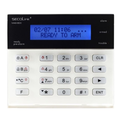
SECOLink
SECOLink KM20B Owner's manual
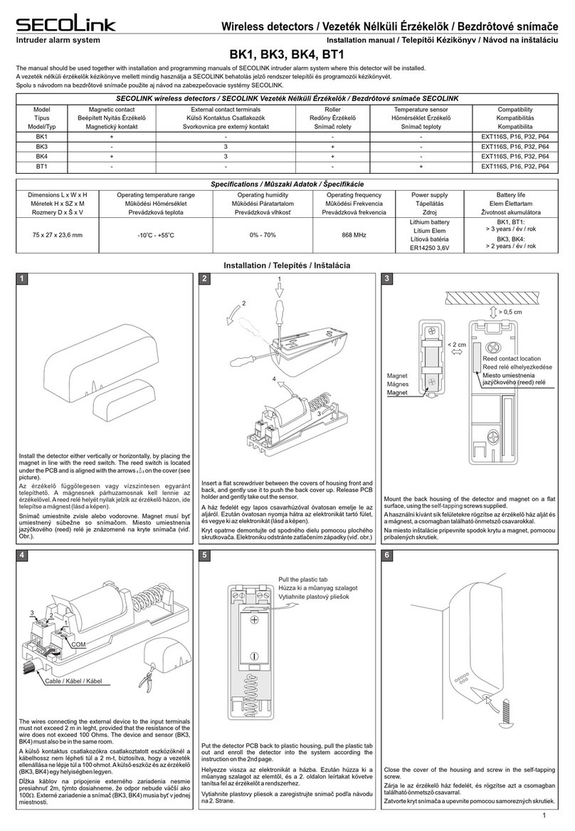
SECOLink
SECOLink BK4 User manual

SECOLink
SECOLink KM25 Owner's manual
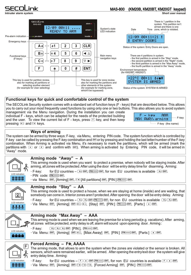
SECOLink
SECOLink MAS-800 Product information sheet
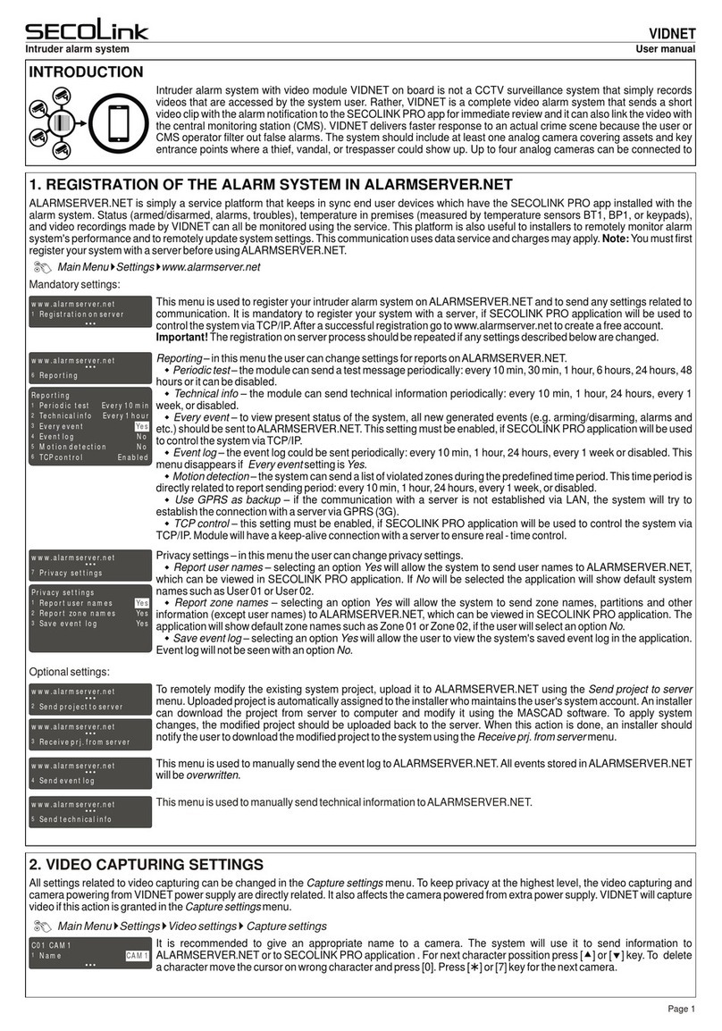
SECOLink
SECOLink VIDNET User manual
SECOLink
SECOLink GSV4B User manual
SECOLink
SECOLink MAS-800 Product information sheet

