iv
______________________________________________________________________________________________________________
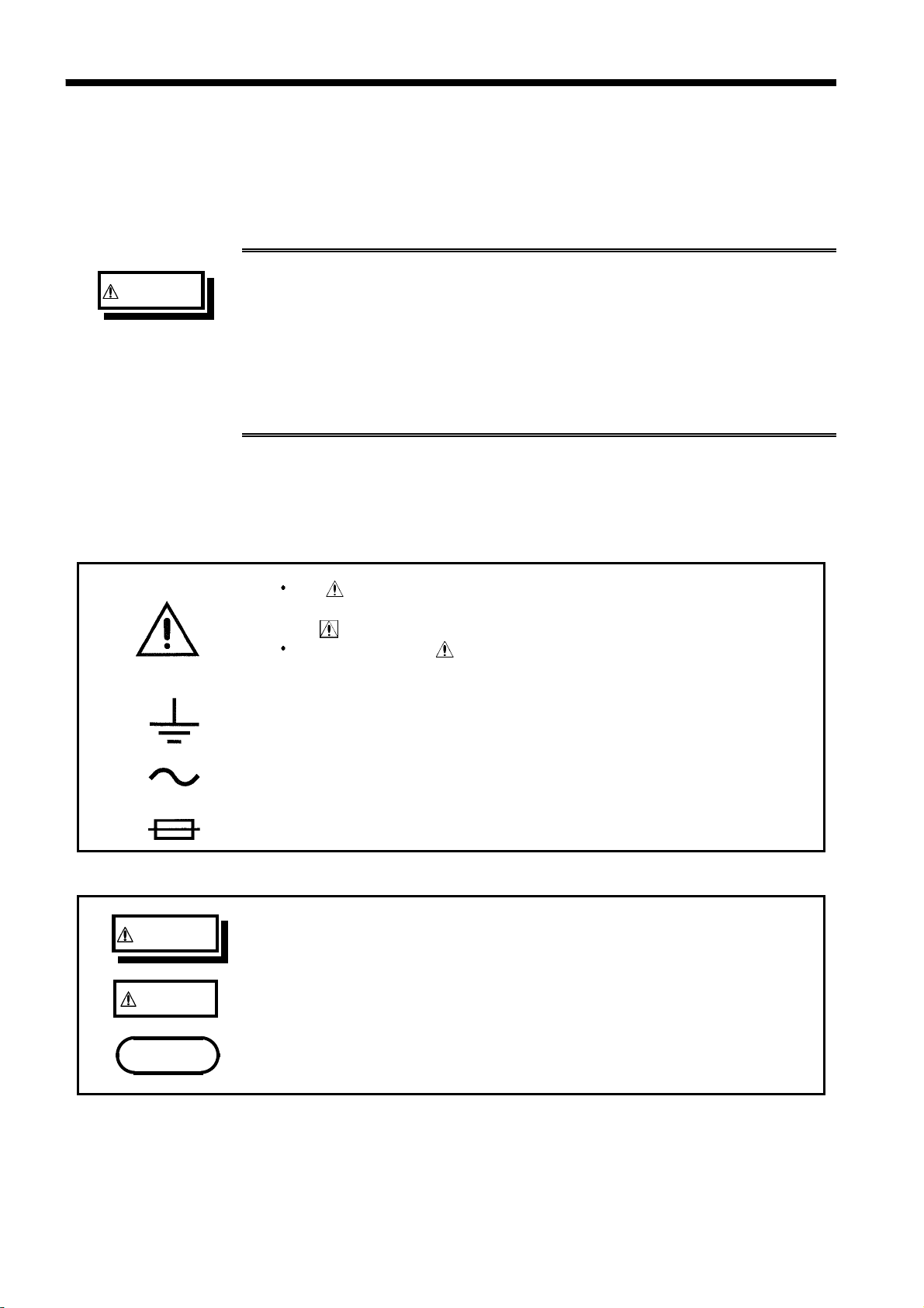
Notes on Use
__________________________________________________________________________________________________
WARNING Before turning the product on, make sure the source voltage
matches that indicated on the product's power connector.
Connection to an improper supply voltage may damage the product
and present an electrical hazard.
To avoid electric shock and ensure safe operation, connect the
power cable to a grounded (3-contact) outlet.
Use this unit near the power supply socket.
The interior of the unit contains some components which are
subject to high voltage, and therefore dangerous. Absolutely do
not remove the cover panel.
CAUTION Various connectors are present on the outside of the 3511-50. Never
connect any cable to any of these connectors without first turning off the
power supply and removing the power cord. Moreover, check the
connections carefully in order to avoid any chance of setting up a short
circuit etc..
In the event that the equipment malfunctions in any manner during use,
turn off the power immediately, and contact your dealer or HIOKI
representative.
Do not store or use the unit where it will be exposed to direct sunlight,
high temperatures, high humidity, or condensation. If exposed to such
conditions, the unit may be damaged, the insulation may deteriorate, and
the unit may no longer satisfy its specifications.
This product should be installed and operated indoors only, between 0
and 40 and 35 to 80%RH. However, it can be safely operated down to
-10 .
The unit should always be stored in a range from -10 to 55 , 80% RH
or less.
Do not store or use the product where it could be exposed to direct
sunlight, high temperature or humidity, or condensation. Under such
conditions, the product may be damaged and insulation may deteriorate
so that it no longer meets specifications.
Do not drop the unit or subject it to severe shock. Doing so can cause
serious damage.
To avoid damage to the product, protect it from vibration or shock during
transport and handling, and be especially careful to avoid dropping.
Notes on Use
Follow these precautions to ensure safe operation and to obtain the full
benefits of the various functions.
Warranty
HIOKI cannot be responsible for losses caused either directly or indirectly by
the use of the unit with other equipment, or if ownership is transferred to a
third party.