Securikey LA GARD 702 User manual
LA GARD 702
High Security Lock for Safes & Vaults
Advanced User Instructions
Keypad firmware 1.2.3.4, Lock firmware 1.2.2.3 (v1)
Introduction
These instructions outline advanced procedures for
operating locks using the Master code and should be used
in conjunction with instructions for Standard Operation,
which are available to download from our website.
When supplied by Safelock Systems Limited, the Master
operates on the code (0-0)-8-7-6-5-4-3-2-1
Buttons
Key
Use
To use commands (Hash #)
To confirm a command (Enter)
Commands
These instructions cover the commands listed below:
Category
Key
Function
Codes
#11
Change code length
#12
Enable or disable dual mode
#17
Force code change
General
operation
#14
Enable or disable the Duress feature
#16
Specify alarm input setting
Audit
#30
Activate PC link
Manager
Management
#50
Add a Manager
#54
Disable or re-enable a Manager
#55
Change Manager privilege
#56
Delete a Manager
#57
Reset a Manager code
Time delay
#73
Enable time delay override feature
Basic commands as listed below are shown in the
Standard Operation instructions.
Basic Commands
Category
Key
Function
Codes
#52
Change code
User
management
#50
Add a User
#54
Disable or re-enable a User
#55
Change user privilege
#56
Delete a User
#57
Reset a User code
Time delay
#72
Amend time delay values
#74
Cancel time delay counting
General
operation
#40
Disable or enable backlit
buttons
#41
Turn keypad beeps off or on
#65
Set time and date
Engineer commands
Additional commands #22, #23, #25, #32, #99 are
available to the Master, which should only be used by
engineers who are servicing the lock.
Visual and acoustic signals
Lock status is indicated with LED flashes and beeps.
Signal
Symbol
Green flash + short high beep
Meaning: Button pressed correctly
☼
Red flash + short low beep
Meaning: Invalid key
☼
3 green flashes + short high beeps
Meaning: Command accepted
☼☼☼
3 red flashes + short low beeps
Meaning: Invalid code or command
☼☼☼
2 red flashes + short low beeps on a key
press or every 10 seconds.
Meaning: The lock is in penalty
☼☼
2 green flashes + high beeps then 2 red
flashes + short low beeps
Meaning: Low battery
☼☼☼☼
3 green flashes + high beeps then 3 red
flashes + short low beeps
Meaning: Critical low battery
☼☼☼
☼☼☼
Red flash + short low beep (Every 10 seconds)
Meaning: Time delay is counting
☼
Green flash + short high beep (Every 10 seconds)
Meaning: The open window is counting
☼
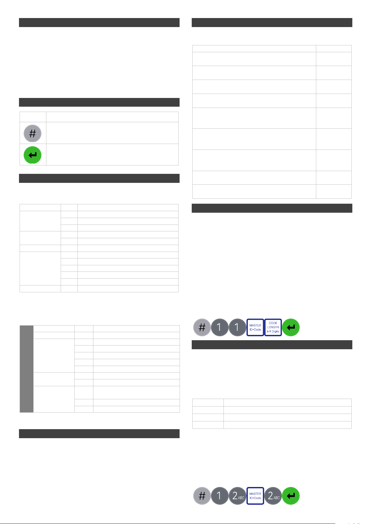
Change code length (#11) Master
By default, the Manager and Users have a code comprised
of a 2-digit ID + 6-digits. The code length can be changed
to have a 2-digit ID + 7, 8 or 9 digits. If changed, existing
Manager and User codes will no longer be valid and will
need their codes to be reset and then changed.
• Enter #11
• Enter the Master ID and code
• Press 6,7,8 or 9 to specify the number of digits required
• Press Enter. If accepted, the lock will signal 3 green
flashes + 3 short beeps ☼☼☼
Example:
Enable or disable dual mode (#12) Master
Dual mode is a feature that requires 2 codes to be Entered
before the lock can be opened. Dual mode can be set up
so that: Dual mode applies to Users only, or Dual mode
applies to Users and the Manager. Dual mode must be
defined as required per the table below.
Key
Mode
1
Dual mode for Users
2
Dual mode for Users + Manager
0
Dual mode disabled
• Enter #12
• Enter the Master ID and code
• Press 1, 2 or 0 as required for the dual mode setting
• Press Enter. If accepted, the lock will signal 3 green
flashes + 3 short beeps ☼☼☼
Example to enable dual mode for Users + Manager:
CURRE NT
ID + NEW
Code
MASTER
ID + Code
CURRE NT
ID + NEW
Code
CURRE NT
ID + NEW
Code
NEW
ID + Code
CODE
LENGTH
6-9 Digits
CURRE NT
ID + NEW
Code
MASTER
ID + Code

Force code change (#17) Master
When a new Manager or User code is added to the lock,
or a code is reset, the system can require that on first use,
the code holder must change their code. By default, force
change is set to being disabled.
• Enter #17
• Enter the Master ID and code
• Press 1 to enable force code change or 0 to disable it.
• Press Enter. If accepted, the lock will signal 3 green
flashes + 3 short beeps ☼☼☼
Example to enable force code change:
Enable or disable Duress (#14) Master
The Duress feature allows a coerced user to Enter a
special variant of their code which opens the lock, and also
generates a silent signal to notify others that safe is being
opened under duress. Connection to an alarm system and
peripheral equipment sold separately is required. Duress
is disable by default.
• Enter #14
• Enter the Master ID and code
• Press 1 to enable duress or 0 to disable it.
• Press Enter. If accepted, the lock will signal 3 green
flashes + 3 short beeps ☼☼☼
Example to enable duress:
A duress code is the user’s normal code with the last digit increased or decreased by 1.
For example, 01-123456 would become 01-123455 or 01-123457. If the normal code ends
with a 0, it can be changed to 9 or 1. If the normal code ends with a 9, it can be changed to
8 or 0.
Specify alarm input setting (#16) Master
With connection to an alarm system and peripheral
equipment sold separately, an alarm input signal can alter
the lock’s operation with one of the settings below:
Setting
Operation
0
Ignore input signal
1
Input signal remote blocks (Prevents the lock
from being opened)
2
Input signal overrides time delay
3
Input signal overrides dual mode
Alarm input signals are ignored by default
• Enter #16
• Enter the Master ID and code
• Press 0, 1, 2 or 3 as required
• Press Enter. If accepted, the lock will signal 3 green
flashes + 3 short beeps ☼☼☼
Example to set remote block:
Audit Master, Manager, User
With licensed software and peripheral equipment sold
separately, an audit of the last 500 lock events can be
downloaded. The audit is stamped with time and date
information based on the clock time of the keypad, as such
it is vital to ensure correct clock time, with annual
updates.
Full instructions to take audit are available on our website.
PC link must be activated using the keypad to start
communication with the software.
Activate PC Link (#30) Authorised Users
To start communication with LA GARD 700 Series
software, PC Link must be activated.
• Enter #30
• Enter a valid ID and code
• Press Enter. If accepted, the lock will signal 3 green
flashes + short beeps ☼☼☼, and the red light will stay
on ☼→
Example to activate PC link:
Manage the Manager Master
In 702 locks supplied by Safelock Systems Ltd, a Manager
is installed with ID 01. To manage the Manager, the
process is the same as for users but only the Master code
is valid to perform the command.
Reset Manager code (#57) Master
If the Manager has forgotten their code, it is possible to
reset it rather than deleting and adding the Manager again.
• Enter #57
• Enter the Master ID and code
• Enter the current ID (Normally 01) and new code twice
• Press Enter. If accepted, the lock will signal 3 green
flashes + short beeps ☼☼☼
Example to reset the Manager code:
Delete Manager (#56) Master
• Enter #56
• Enter the Master ID and code
• Enter the ID to be deleted (Normally 01)
• Press Enter. If accepted, the lock will signal 3 green
flashes + short beeps ☼☼☼
Example to delete the Manager:
CURRE NT
ID + NEW
Code
MASTER
ID + Code
CURRE NT
ID + NEW
Code
MASTER
ID + Code
CURRE NT
ID + NEW
Code
MASTER
ID + Code
CURRE NT
ID + NEW
Code
CURRE NT
ID + NEW
Code
NEW
ID + Code
ID
+
Code
CURRE NT
ID + NEW
Code
MASTER
ID + Code
CURRE NT
ID + NEW
Code
CURRE NT
ID + NEW
Code
CURRE NT
ID + NEW
Code
MASTER
ID + Code
CURRE NT
ID + NEW
Code
CURRE NT
ID + NEW
Code
NEW
ID + Code

Add the Manager (#50) Master
Generally, the Manager code can be reset rather than
being deleted. If the Manager code has been deleted, it
can be added again or assigned to a different ID.
Manager privilege
When the Manager is added, the privilege must be
defined.
Key
Privilege
1
Open only
2
Audit only
3
Open and audit
5
Open and override time delay*
7
Open, audit and override time delay*
*If the Manager is defined as being able to override time delay, the
feature must be enabled using #73 see Advanced Operation.
Add the Manager
• Enter #50
• Enter the Master ID and code
• Enter ID 01 and new code
• Press 4 to indicate ‘Manager’
• Press 1, 2, 3, 5 or 7 to indicate the privilege setting
• Press Enter. If accepted, the lock will signal 3 green
flashes + short beeps ☼☼☼
Example to add the Manager:
Disable or re-enable the Manager (#54) Master
• Enter #54
• Enter the Master ID and code
• Enter the ID to be disabled or enabled (Normally 01)
• Press 0 to disable the code or 1 to enable it
• Press Enter. If accepted, the lock will signal 3 green
flashes + short beeps ☼☼☼
Example to disable the Manager:
Change Manager privilege (#55) Master
It is possible to redefine the Manager’s privilege per the
table shown in Add the Manager
• Enter #55
• Enter the Master ID and code (Normally 01)
• Enter the ID to be changed
• Press 1, 2, 3, 5 or 7 to indicate the privilege setting
• Press Enter. If accepted, the lock will signal 3 green
flashes + short beeps ☼☼☼
Example to change user privilege:
Enable or disable time delay override Master
Users profiled with time delay override privilege cannot
use the privilege unless time delay override has been
enabled. Time delay override is disabled by default.
• Enter #73
• Enter the Master ID and code
• Press 1 to enable time delay override or 0 to disable it.
• Press Enter. If accepted, the lock will signal 3 green
flashes + 3 short beeps ☼☼☼
Example to enable time delay override:
Engineer commands Master
Additional commands are available to the Master, which
should only be used by engineers who are servicing the
lock. More information can for engineers can be found on
our website.
Key
Function
#22
Install a lock onto a keypad
#23
Uninstall a lock from a keypad
#25
Reset the lock to factory settings
#32
Install a new keypad onto an existing lock
(Command also available to Manager and Users)
#99
Initiate communication for a firmware update
If a lock is reset, it must be setup using the LA GARD
700 series software to correctly configure DST
settings so that the audit time and date data is
accurate.
Document version
These instructions may be updated from time to time to
reflect firmware changes, visit safelocksystems.co.uk to
check for updates.
CURRE NT
ID + NEW
Code
MASTER
ID + Code
CURRE NT
ID + NEW
Code
CURRE NT
ID + NEW
Code
NEW
ID + Code
CURRE NT
ID + NEW
Code
MASTER
ID + Code
CURRE NT
ID + NEW
Code
CURRE NT
ID + NEW
Code
NEW
ID + Code
CURRE NT
ID + NEW
Code
MASTER
ID + Code
CURRE NT
ID + NEW
Code
CURRE NT
ID + NEW
Code
NEW
ID + Code
CURRE NT
ID + NEW
Code
MASTER
ID + Code
Other Securikey Lock manuals


