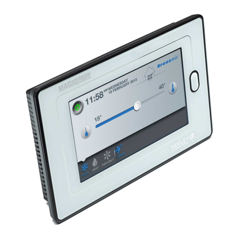
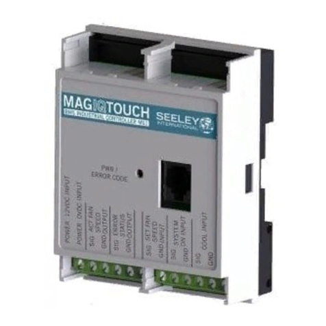
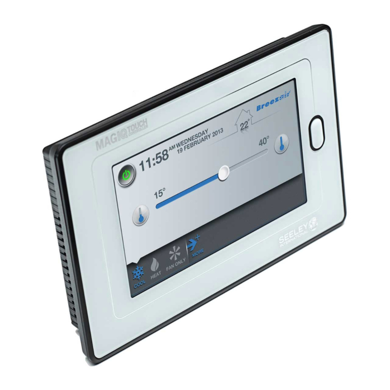
Seeley CW-H 2020 PLC User manual

OWNER’S MANUAL
CW-H 2020 PLC WALL CONTROLLER
(English)
Original English Instructions
ILL2468-A


CW-H COOLER PLC OWNER’S MANUAL 859731-D |1
TABLE OF CONTENTS
CW-H PLC WALL CONTROL
Models: All CW-H 2
Kit Contents 2
Specications 2
QUICK START
24VdcPowerAndRS485ModbusCommunicationsWiring 3
RS 485 Modbus Cooler Node Address 4
RS 485 Modbus Network Setup - First Time Use 4
PHYSICAL DESCRIPTION & MOUNTING
WallControlDimensionsAndSetupNotes 5
WallControlInstallationInstructions 6
CONNECTING
CommunicationCableSpecication 7
WiringRequirements 7
Power 8
TerminatingResistor 9
OPERATION SCREENS
MainMenu 10
CoolMode(ManualSpeedControl) 11
CoolMode(AutomaticSpeedControl) 12
VentMode 13
ProgramMode 14
EditThe7-DayProgram 15
SETTING SCREENS
ScreenDisplay 16
TimeAndDate 17
Language 17
SecurityLock 18
Conguration 18
Network 19
Auto-Restart 20
RoomSensor 20
AmbientSensor 20
Device 21
Monitor 21
FaultHistory 22
FaultScreenDisplay 23
BMS Lock 24
COOLER FAULTS AND TROUBLESHOOTING
TroubleshootingTable 25
OtherPotentialProblems 26
APPENDIX
ExampleWiringSchematic 27

2 |859731-D
CW-H PLC WALL CONTROL
MODELS: ALL CW-H
TheseinstructionsaretobereadinconjunctionwiththeInstallationandOperationand
Maintenanceguidesuppliedwiththecooler.
KIT CONTENTS
SPECIFICATIONS
General
Powersupply 24Vdc+/-10%
Power consumption 3.2VA1.3Wmax
DegreeofProtection IP20
Mounting VerticalWall,Flush
AmbientoperatingTemperature 0to50oC(32to122oF)
Ambientoperatinghumidity(non-condensing) 0to75%
Ambientstoragetemperature -30to50oC(-22to122oF)
Ambientstoragehumidity(non-condensing) 0to75%
Embedded Temperature Sensor Characteristics
Type 10kNTCtype2thermistor
Resolution +/-0.1oC(+/-0.2oF)
Measurementrange -40to+50oC(-40to+122oF)
Accuracy +/-0.5oC(+/-0.9oF)at21oC(70oF)
typicalcalibration
Embedded Humidity Sensors Characteristics
Typeandcalibration Singlepointcalibratedbulkpolymer
Precision Readingrangefrom10to90%R.H.non-condensing
10to20%precision:10%
20to80%precision:5%
80to90%precision:10%
Stability Lessthan1.0%yearly(typicaldrift)
Communication
Type RS485ModbusMaster
Maximumofnumberofslavedevices 15
ITEM IMAGE ITEM IMAGE
ClimateWizard
WallController
IsolatingScrew
MODBUS120Ω
Terminating
Resistor
Instructions
ITEM 1 ITEM 2
ILL2425-A

CW-H COOLER PLC OWNER’S MANUAL 859731-D |3
ILL3631-C
RS 485 +
RS 485 -
RS 485 GND
W/C +24Vdc
W/C 0Vdc
RS 485 +
RS 485 -
RS 485 GND
SENSOR U1
SENSOR U2
SENSOR G0
SENSOR G
TO WALL CONTROLLER
TO NEXT COOLER TO ROOM SENSOR
(OPTIONAL KIT)
120 OHM MODBUS TERMINATING RESISTER
TO BE FITTED TO LAST COOLER ONLY
SENSOR U1
SENSOR U2
SENSOR G0
SENSOR G
TO AMBIENT SENSOR
(OPTIONAL KIT)
24Vdc POWER AND RS 485 MODBUS COMMUNICATIONS WIRING
120
Ω
ILL3630-B
RS 485 -
RS 485 +
GND
-
ILL3630-B
QUICK START
WALL
CONTROLLER
CW-H
COOLER
ILL3631-C

4 |859731-D
RS 485 MODBUS COOLER NODE ADDRESS
Screen Layout
ILL3632-B
RS 485 MODBUS NETWORK SETUP - FIRST TIME USE
IMPORTANT-ThisClimateWizardWallControllercancontrolupto15CW-Hcoolers.Ensure
eachcoolerispoweredupandhasauniquenodeaddressset.Refertoinstallationliterature
providedwiththecoolerforsetupinstructions.
EnterSETTINGS–CONFIGURATION–NETWORKmenu
ILL3633-C
ILL3633-B
Listshowsalldetectedcoolers.
PressSAVEtocommitdetectedcoolerstoWallControlmemory.
QUICK START
ILL3632-A
INTERNAL
TEMPERATURE /
HUMIDITY
TIME
ON - OFF
COOL MODE
VENT MODE
PROGRAM MODE
SETTINGS
DATE
DATE TIME
ON OFF
COOL MODE
VENT MODE INTERNAL
TEMPERATURE /
HUMIDITY
PROGRAM MODE
SETTINGS

CW-H COOLER PLC OWNER’S MANUAL 859731-D |5
ILL3672-A
Number Description
1Colour touchscreen
2Powersupplyconnector
3RS 485 Modbus connector
4Holesfortemperatureandhumiditymeasurement
TheClimateWizardWallControllershouldbeplacedindoors,approximately1.5metres(5’)above
theoor,inthesamezoneinwhichcoolingisrequired.Placementiscriticalforcorrectfunctioning
ofthetemperatureandhumiditysensorsinsidetheController.
Thefollowingpointsmustbetakenintoconsideration:
• Avoiddirectsunlightexposure.
• Avoidmountingonexternalwalls.
• Avoidmountingthewallcontrolnearheatsourcessuchasstovesandtelevisions.
• Donotlocateinthedirectairowoftheductoutlets.
• Donotlocateinstrongdraftsorindeadspotssuchascupboards/drawers.
• Alwayssealthewallcableentryhole.
• AvoidblockingorrestrictingtheventholeslocatedontheundersideoftheController,asthis
iswherethesensorsarelocated.Important!Draftswithinthewallcavitycanimpactthe
temperatureandhumidityreadingofthewallcontrol.Werecommendthatthecableaccess
holebesealed,butinsuchawaythatthecablecanstillretreatintothewallcavity.
• TheControllershallbemountedvertically.
PHYSICAL DESCRIPTION & MOUNTING
WALL CONTROL DIMENSIONS AND SETUP NOTES
ILL3672-A
1
2
3
44

6 |859731-D
ILL3670-A
Step Action
1 Openunitbypullingonbottomsideofthedisplay(1)
2Ensurecorrectsideofbasefacesup
3 Pullcables150mm(5.90in.)outfromwall
4Alignbaseandmarklocationoftwomountingholesonwallorpanel(2)
CAUTION!
Alwaysmakesuretherearenoelectricalcables,gasorwaterpipes,orthelike,behind
whereyouintendtodrill.
5Installanchors(NOTINCLUDED)inwall(3)
6 Insertcableincentralholeofbase
7 Placerearcoveronthewallandalignitwithmountingholes(4)
8Insertscrews(NOTINCLUDED)inmountingholesoneachsideofbase(5)
9 InsertPOWERandCONTROLwiringaccordingtowiringchart
10 Gentlypushexcesswiringbackintohole
11 Gentlyaligncovertotopofbaseandsnapinplacefrombottom(6)
12 Installtheisolatedscrewconnectionforsecuringtheplastichousing(7)
PHYSICAL DESCRIPTION & MOUNTING
WALL CONTROL INSTALLATION INSTRUCTIONS
ILL3671-A
ILL3670-A

CW-H COOLER PLC OWNER’S MANUAL 859731-D |7
ILL3669-A
CONNECTING
C
mm2
mm2
AWG
AWG
7
7
0.28
0.28
mm
mm
0.2...2.5
24...14 24...14 22...14
0.5...0.6
4.42...5.31
22...14 2x 24...18 2x 24...16
2x 22...18 2x 20...16
0.2...2.5 0.25...2.5 0.25...2.5 2x 0.2...1 2x 0.2...1.5
2x 0.25...1 2x 0.5...1.5
in.
in.
N/m
Ø3.5mm (0.14in)
lb/in
COMMUNICATION CABLE SPECIFICATION
• SuitableforRS485applications
• Minimum1twistedpair(TP)andathirdconductor
• Copper Conductors
• 0.5mm2/AWG20
• BraidedShieldwithDrainWire
• Characteristicimpedance120Ω
• Nominalcapacitybetweenconductors89pF/m
• Nominalcapacitybetweenconductorsandshielding161pF/m
Usethetwistedpairforthe‘+’and‘-‘signalterminals.Usethe3rdconductorfortheGND
terminals.Attachthebraidedshield/drainwiretoanEARTHpointatoneendonly.
ILL3705-A
ILL3705-A
WIRING REQUIREMENTS
• CommunicationwiringmustbekeptseparatefromACpowerwiring.
• Alwaysroutecommunicationcablesatleast300mm(12”)awayfromhighvoltagecablesand
high-powermachines.
• Crossoverhighpowercablesatrightangles.
• MaximumcablelengthtorstCW-Hcooleris100m.
• MaximumcablelengthbetweeneachCW-His100m.
Note:Non-shieldedcablesarenotprotectedagainstelectromagnetinterferencewhichcancause
signaldegradation.
Attach the 120Ω resistor (supplied with Wall Controller) between the "+" and "-" terminals of
the Wall Controller
Attach the 120Ω resistor (supplied with CW-H cooler) between the "+" and "-" terminals of
the last CW-H cooler on the RS 485 Modbus network.
Donottthe120ΩresistorsuppliedwiththeremainingCW-HcoolerinstalledbetweentheWall
ControllerandthelastCW-Hcoolers.
SeeAnnexAforexamplewiringschematics

8 |859731-D
POWER
Characteristic Specication
Powersupply 24Vdc+/-10%
Power consumption 3.2VA1.3Wmax
FuseRecommendation(notincluded) TypeT500mA
TheClimateWizardWallControllercanbepoweredviaeitheraCW-Hcooleronthenetworkora
dedicatedpowersupply
Note:ShouldtheCW-HcoolerusedforprovidingpowerbeturnedotheWallControllerwillbeun-
abletocontroltheremainingcoolersonthenetwork.
Useproperwiresizestomeetvoltageandcurrentrequirementsandcopperconductors.
Ifusingadedicatedpowersupply,itmustberatedSafetyExtraLowVoltage(SELV)accordingto
IEC61140.Thesesourcesofpowerareisolatedbetweentheelectricalinputandoutputcircuitsof
thepowersupplyaswellassimpleseparationfromground(earth),PELV,andotherSELVsystems.
CONNECTING
ILL3637-A
ILL3637-A
WALL
CONTROLLER
CW-H
COOLER
+24Vdc
0Vdc
W/C +24Vdc
W/C 0Vdc
TO WALL CONTROLLER
ILL3639-B
ILL3639-B

CW-H COOLER PLC OWNER’S MANUAL 859731-D |9
CONNECTING
Attachthe120Ωresistor(suppliedwithWallController)betweenthe“+”and“-”terminalsofthe
WallControl
Attachthe120Ωresistor(suppliedwithCW-Hcooler)betweenthe“+”and“-”terminalsoftheLAST
CW-HcoolerontheRS485Modbusnetwork.
ILL3638-B
TERMINATING RESISTOR
WALL
CONTROLLER
CW-H
COOLER
ILL3638-B
GND
ILL3631-C
RS 485 +
RS 485 -
RS 485 GND
W/C +24Vdc
W/C 0Vdc
RS 485 +
RS 485 -
RS 485 GND
SENSOR U1
SENSOR U2
SENSOR G0
SENSOR G
TO WALL CONTROLLER
TO NEXT COOLER TO ROOM SENSOR
(OPTIONAL KIT)
120 OHM MODBUS TERMINATING RESISTER
TO BE FITTED TO LAST COOLER ONLY
SENSOR U1
SENSOR U2
SENSOR G0
SENSOR G
TO AMBIENT SENSOR
(OPTIONAL KIT)
ILL3631-C

10 |859731-D
MAIN MENU
OPERATION SCREENS
ILL3632-B
ILL3632-A
INTERNAL
TEMPERATURE /
HUMIDITY
TIME
ON - OFF
COOL MODE
VENT MODE
PROGRAM MODE
SETTINGS
DATE
DATE TIME
ON OFF
COOL MODE
VENT MODE INTERNAL
TEMPERATURE /
HUMIDITY
PROGRAM MODE
SETTINGS

CW-H COOLER PLC OWNER’S MANUAL 859731-D |11
OPERATION SCREENS
COOL MODE (MANUAL SPEED CONTROL)
UseCOOLmodewithmanualspeedcontroltokeeptheconnectedcooler(s)runningataconstant
fanspeed.
ILL3642-B
ILL3642-B
ToenableCOOLmodewithmanualspeedcontrol,
• PresstheON-OFFbutton.
• PresstheCOOLmodebuttononce.
• PresstheINDIRECTand/orDIRECT*buttonsasrequiredtoenabletherespectivecooling
stages.
• PresstheFANSPEEDUPDOWNarrowbuttonstosetfanspeed.
*Note: RelativehumiditysetpointbuttonsareonlyavailableifCW-HSupercoolcooler(s)are
detectedduringNetworkSetup.
ON OFF
COOL MODE
(MANUAL CONTROL)
INDIRECT COOLING
STAGE ON / OFF
* DIRECT COOLING
STAGE ON / OFF
FAN SPEED
INCREASE / DECREASE

12 |859731-D
OPERATION SCREENS
COOL MODE (AUTOMATIC SPEED CONTROL)
UseCOOLmodewithautomaticspeedcontroltomaintainspacetemperatureandrelative
humidity*byautomaticallyvaryingtheconnectedcooler(s)fanspeed.
ILL3643-B
ILL3643-B
ToenableCOOLmodewithautomaticspeedcontrol,
• PresstheON-OFFbutton.
• PresstheCOOLmodebuttontwice.
• Setthetargetinternaltemperature.Setpointcanbeadjustedinincrementsof0.5oC(1oF)
between15oCand30oC(60oFand85oF).
Coolerfanspeedwillbeadjustedtotrytomaintainthistemperature.
• Setthetargetrelativehumidity*.Setpointcanbeadjustedinincrementsof5%between50%
and90%.
CoolerwillenabletheDIRECTcoolingstageifmeasuredinternalRHislowerthanthe
setpoint.
CoolerwilldisabletheDIRECTcoolingstageifmeasuredinternalRHishigherthanthe
setpoint.
*Note: RelativehumiditysetpointbuttonsareonlyavailableifCW-HSupercoolcooler(s)are
detectedduringNetworkSetup.
ON OFF
COOL MODE
(AUTO CONTROL)
* RELATIVE HUMIDITY
INCREASE / DECREASE
INTERNAL TEMPERATURE
INCREASE / DECREASE
(ONLY SHOWS IF
SUPERCOOL ENABLED -
SEE CONFIGURATION)

CW-H COOLER PLC OWNER’S MANUAL 859731-D |13
OPERATION SCREENS
VENT MODE
UseVENTmodewithmanualspeedcontroltokeepconnectedcooler(s)runningataconstant
speedwithnocoolingstageenabled.
ToenableVENTmodewithmanualspeedcontrol,
• PresstheON-OFFbutton.
• PresstheVENTmodebutton.
• PresstheFANSPEEDUPDOWNarrowbuttonstosetfanspeed.
ILL3644-C
ILL3644-C
ON OFF
VENT MODE
FAN SPEED
INCREASE / DECREASE

14 |859731-D
ILL3645-C
OPERATION SCREENS
ILL3645-C
ON - OFF
PROGRAM MODE READ ONLY
DETAILS
EDIT BUTTON
PROGRAM MODE
UsePROGRAMmodetomaintainspacetemperatureandrelativehumidity*ona“setandforget”
seven-dayprogram.
PROGRAMmodedivideseachdayintofourtimeperiodswiththeuserabletosetwheneachof
theseperiodsstarts,endsandtherequiredset-pointsviatheSETTINGSmenu.
WhenPROGRAMmodeisenabled,thewallcontrollerwillcheckthecurrentday,time,temperature
andrelativehumiditysetpointsagainsttherealtime/currentvaluesandruntheconnectedcooler(s)
asrequired.
ToenablePROGRAMmode,
• PresstheON-OFFbutton.
• PressthePROGRAMmodebutton.
Thecontrollerwilldisplaythecurrenttimeperiod.
*Note: RelativehumiditysetpointbuttonsareonlyavailableifCW-HSupercoolcooler(s)are
detectedduringNetworkSetup.
ON OFF
PROGRAM MODE
READ ONLY
DETAILS
EDIT BUTTON

CW-H COOLER PLC OWNER’S MANUAL 859731-D |15
OPERATION SCREENS
EDIT THE 7-DAY PROGRAM
Toeditthe7-dayprogram,presstheEDITbutton..
ILL3653-C
Eachdayisdividedintofourtimeperiodswiththeuserabletosetwheneachoftheseperiods
startsandendsandtherequiredtemperature/relativehumidity*set-points.
Intheaboveexample,theconnectedcoolersareprogrammedforthefollowingsequence;
07:00–TurnON,withset-pointsof24Cand60%RH
11:00–TurnOFF(set-pointsareignored)
16:00–TurnON,withset-pointsof24Cand60%RH
22:00–TurnOFF(set-pointsareignored)
Presstheleftandrightarrowbuttonstocyclethrougheachdayoftheweek.Whennishedsetting
ascheduleforaparticularday,pressSAVEDAY.Alternatively,pressSAVEALLtosavetheshown
scheduletoalldays.
*Note: RelativehumiditysetpointbuttonsareonlyavailableifCW-HSupercoolcooler(s)are
detectedduringNetworkSetup.
ILL3653-C
SET PERIOD STATUS AND
START TIME
SAVE PROGRAM TO ALL DAYS
PRESS TO CYCLE THROUGH ALL
DAYS
* SET PERIOD TEMPERATURE AND
HUMIDITY SET POINTS
SAVE PROGRAM TO DAY
SELECTED AT THE TOP OF
SCREEN

16 |859731-D
ILL3646-B
ILL3647-D
SCREEN DISPLAY
SETTING SCREENS
ILL3646-B
SETTINGS
ILL3647-D
SETUP TIME AND DATE
WALL CONTROLLER
SOFTWARE VERSION
CONFIGURE COOLER SETTINGS
VIEW CONNECTED DEVICES
ENABLE/DISABLE
SECURITY LOCK
SETUP LANGUAGE
SETUP TIME AND DATE
CONFIGURE COOLER SETTINGS
VIEW CONNECTED DEVICES
WALL CONTROLLER
SOFTWARE VERSION
SETUP LANGUAGE
ENABLE/DISABLE
SECURITY LOCK

CW-H COOLER PLC OWNER’S MANUAL 859731-D |17
TIME AND DATE
Toadjustthetimeanddate,presseachcomponentandtypeinthecorrectvalueusingtheon-
screenkeyboard.
Whennished,pressSAVE.
ThesevaluesareusedinthePROGRAMmodeandfortimestampingfaultcodes
ILL3648-A
ILL3648-A
SETTING SCREENS
LANGUAGE
ILL3827-A
ILL3827-A
TochangetheWallControllerLanguagepresstheChangeLangaugeboxandselectfrom
ENGLIGH(default),SPANISH,ITALIANandFRENCH.
Note:TheWallControllerwillautomaticallyrestartifthelanguageischanged.

18 |859731-D
CONFIGURATION
ILL3829-A
UsetheCONFIGUATIONscreentoset-upallCW-HcoolersconnectedtotheWallController.
SETTING SCREENS
CONFIGURE COOLER
SETTINGS
NETWORK
ROOM SENSORS
AMBIENT SENSORS
AUTO
RESTART
ILL3829-A
SECURITY LOCK
ILL3828-A
ILL3828-A
First Time Use.UponenablingSecurityLockforthersttime,theuserisrequiredtoseta4digit
userpasscode.Ifenabled,theSecurityLockscreenwillappear60secondsafterthescreenhas
beenidle.
EntertheuserpasscodetoremovetheSecurityLockscreenandmakechangestotheWall
Controlleroperatingmode.
PressthebackbuttontoviewtheWallControlleroperatingmode.Nochangesareallowed.
PresstheServiceButtontoentertheSeeleyService7378passcode.Fullaccessisgranted.
Iftheuserpasscodeisenteredincorrectly5timestheReset5331passcodeisrequired.
CONFIGURE
COOLER
SETTINGS
NETWORK
AUTO
RE-START
AMBIENT
SENSORS
ROOM
SENSORS
Table of contents
Other Seeley Controllers manuals
Popular Controllers manuals by other brands

RMG
RMG 672 OPERATING AND MAINTENANCE INSTRUCTIONS/ SPARE PARTS

Astral Pool
Astral Pool Connect LITE+ Installation and operating instructions

PPI
PPI Neuro 102EX user manual

NovaStar
NovaStar NovaPro UHD Jr user manual

Fairchild
Fairchild 1600A Installation, operation and maintenance instructions

TQ
TQ TQMxE40C1 user manual