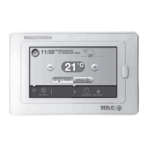
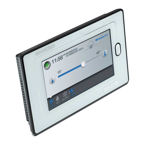
Seeley MAGICTOUCH MS1 User manual

SIG
GND
ERROR
STATUS
OUTPUT
COOL INPUT
ACTUAL FAN
SPEED
OUTPUT
SIG
GND
SIG
GND
SYSTEM
ON INPUT
SET FAN
SPEED
INPUT
PWR /
ERROR CODE
SIG
GND
SIG
GND
+12VDC
0VDC
POWER
INPUT
BMS INDUSTRIAL CONTROLLER M1
BMS INDUSTRIAL CONTROLLER MS1
ILL2470-A
INSTALLATION &
OPERATION MANUAL
MagIQtouch BMS Industrial Controller MS1
(Coolers Only)
Original English Instructions
(English) (Industrial Controller MS1)

i |
™™

MAGIQTOUCH BMS INDUSTRIAL CONTROLLER - MANUAL |1
TABLE of contents
KIT CONTENTS 2
SAFETY 3
EMPLOYER AND EMPLOYEE RESPONSIBILITIES 3
Installer and Maintenance Contractors – Risk Assessment 3
Other Important Points to Consider: 3
INSTALLATION PREPARATION 4
COMMUNICATION CABLE 5
Master Mode - Maximum Cable Length 5
Slave Mode - Maximum Cable Length 5
INSTALLATION 7
Mounting - Din Rail 7
Mounting - Wall Mount 7
ELECTRICAL INSTALLATION 8
Typical Installation Options 8
Master Mode - Single Cooler 8
Master Mode - Multi Coolers 8
Slave Mode - Single Cooler Option 1 9
Slave Mode - Single Cooler Option 2 9
Slave Mode - Multiple Coolers Option 1 10
Slave Mode - Multiple Coolers Option 2 10
Master Or Slave Mode 11
Master Mode 11
Slave Mode 11
Activating Master Or Slave Mode 11
Connecting Cooler or Wall Control to BMS MS1 12
Inputs Signals 13
Voltage Levels for Set Fan Speed Analogue Input. 14
Output Signals 15
Error Status 15
Actual Fan Speed 16
Diagnostic LED's 17
CONNECTION DIAGRAM 18
TROUBLE SHOOTING 19

2 |
™
KIT CONTENTS
Contents
Item Images Qty Description
1
SIG
GND
ERROR
STATUS
OUTPUT
COOL INPUT
ACTUAL FAN
SPEED
OUTPUT
SIG
GND
SIG
GND
SYSTEM
ON INPUT
SET FAN
SPEED
INPUT
PWR /
ERROR CODE
SIG
GND
SIG
GND
+12VDC
0VDC
POWER
INPUT
BMS INDUSTRIAL CONTROLLER M1
BMS INDUSTRIAL CONTROLLER MS1
ILL2470-A
1 MaglQtouch Industrial Controller MS1
21 Installation and Operation Manual
32 Wall Brackets
42 Wall Plug Yellow 5mm
52 Screw PAN PHIL 6ABX1” ZNP
6
ILL2471-A
1 3m Communications Cable
ILL2109-A
SIG
GND
ERROR
STATUS
OUTPUT
COOLINPUT
ACTUALFAN
SPEED
OUTPUT
SIG
GND
SIG
GND
SYSTEM
ONINPUT
SETFAN
SPEED
INPUT
PWR/
ERRORCODE
SIG
GND
SIG
GND
+12VDC
0VDC
POWER
INPUT
BMSINDUSTRIAL CONTROLLER M1
BMSINDUSTRIALCONTROLLER MS1
ILL2470-A
INSTALLATION &
OPERATION MANUAL
MagIQtouch BMS Industrial Controller MS1
(Coolers Only)
Original English Instructions
(English) (Industrial Controller M1)
BMS INDUSTRIAL CONTROLLER M1
BMS INDUSTRIAL CONTROLLER MS1
TM

MAGIQTOUCH BMS INDUSTRIAL CONTROLLER - MANUAL |3
SAFETY
This document provides technical guidance on the installation and operation of the
MagIQtouch BMS Industrial Controller MS1.
EMPLOYER AND EMPLOYEE RESPONSIBILITIES
Please read this manual carefully. Your failure to do so could result in injury to you or
damage to the cooler and property.
The installation and maintenance of coolers at height has the potential to create
Occupational Health and Safety issues for those involved. Installers are advised to
ensure they are familiar with Local Acts, Regulations and Standards, which may oer
practical guidance on health and safety issues. Compliance with these regulations will
require appropriate work practices, equipment, training and qualications of workers.
INSTALLER AND MAINTENANCE CONTRACTORS – RISK ASSESSMENT
Seeley International provides the following information as a guide to contractors and
employees to assist in minimising risk whilst working at height.
A risk assessment of all hazardous tasks is required under legislation. A risk assessment
is an essential element that should be conducted before the commencement of work, to
identify and eliminate the risk of falls or to minimise these risks by implementing control
measures. There is no need for this to be a complicated process, it just is a matter
of looking at the job to be done and considering what action(s) are necessary so the
person doing the job does not injure themselves.
This should be considered in terms of:
What are the chances of an incident happening?
What could the possible consequence be?
What can you do to reduce, or better still, completely get rid of the risk?
WARNING!
The MagIQtouch BMS Controller requires an approved Safety Extra Low Voltage (SELV)
12Vdc power supply to be connected to the power supply input of the MagIQtouch BMS
controller. The outputs from the controller require this approved SELV power supply in
order to maintain the SELV circuit. Except for the RJ 6 way connection to the cooler,
other inputs and outputs should only be connected to the SELV circuit of the building
management system. Interconnection wiring between the MagIQtouch BMS controller
and the building management system shall be separated by reinforced insulation to any
live parts. Installation and location of the BMS controller shall be suciently separated
from live parts to comply with reinforced insulation.
This MagIQtouch BMS Industrial Controller is to be installed indoors only, installation
shall only be performed by suitably trained and qualied personnel, in accordance with
local and national wiring rules.
This appliance is not intended for use by persons (including children) with reduced
physical, sensory or mental capabilities, or lack of experience and knowledge, unless
they have been given supervision or instruction concerning use of the appliance by a
person responsible for their safety. Children should be supervised to ensure that they
do not play with the appliance. If any cables are damaged, they shall be replaced by the
manufacturer or its service agent or similarly qualied person in order to avoid a hazard.
Stranded conductors shall not be consolidated by lead-tin soldering where they are
subject to contact pressure, i.e. on terminal block.

4 |
™
INSTALLATION PREPARATION
WARNING! THIS INSTALLATION SHOULD ONLY BE PERFORMED BY SUITABLY
TRAINED AND QUALIFIED PERSONNEL, IN ACCORDANCE WITH LOCAL AND
NATIONAL WIRING RULES.
Before commencing work on the cooler, ensure it is disconnected from the power
source, when installing the MagIQtouch BMS Industrial Controller select and prepare an
appropriate mounting site with the following features:
• Space for mounting on either DIN rail or directly to the wall.
• Clearance for inserting digital & analogue inputs & outputs.
• Within 100m of cooler.
• Dedicated 12Vdc power input for "Actual" fan speed and logic Error Status signal.
Note! Do not use power boards and double adaptors!

MAGIQTOUCH BMS INDUSTRIAL CONTROLLER - MANUAL |5
ILL2472-A
COMMUNICATION CABLE
The communication cable from the Cooler Controller to the MagIQtouch BMS Industrial
Controller are 26AWG, 7/0.16, 6 core at cable.
• 20m/66’ cable is supplied with each Seeley cooler or heater.
Important! Supplied cables should not be altered. Failure of the product or components
to operate correctly due to modication to supplied cables, or the use of non-approved
cable will NOT be accepted under the Manufacturer’s warranty.
100m / 328'
MAX
Seeley International cooler
SIG
GND
ERROR
STATUS
OUTPUT
COOL INPUT
ACTUAL FAN
SPEED
OUTPUT
SIG
GND
SIG
GND
SYSTEM
ON INPUT
SET FAN
SPEED
INPUT
PWR /
ERROR CODE
SIG
GND
SIG
GND
+12VDC
0VDC
POWER
INPUT
BMS INDUSTRIAL CONTROLLER M1
BMS INDUSTRIAL CONTROLLER MS1
ILL2472-A
MASTER MODE - Maximum cable length
SLAVE MODE - Maximum cable length
Seeley International cooler
SIG
GND
ERROR
STATUS
OUTPUT
COOL INPUT
ACTUAL FAN
SPEED
OUTPUT
SIG
GND
SIG
GND
SYSTEM
ON INPUT
SET FAN
SPEED
INPUT
PWR /
ERROR CODE
SIG
GND
SIG
GND
+12VDC
0VDC
POWER
INPUT
BMS INDUSTRIAL CONTROLLER M1
BMS INDUSTRIAL CONTROLLER MS1
LINK MODULE
≤20m / 66' MAX
≤3m/10' MAX
≤20m / 66' MAX
ILL2481-A
ILL2481-A

6 |
™
Part No. Length Details
862873 1.5m/5' MagIQtouch Industrial Wall Controller cable (No ferrite)
861265 3m/10' MagIQtouch Industrial Wall Controller cable (No ferrite)
833880 20m/66’ MagIQtouch Industrial Wall Controller cable (No ferrite)
823553 20m/66’ MagIQtouch Industrial Wall Controller cable (ferrite)
864396 30m/98’ MagIQtouch Industrial Wall Controller cable (ferrite)
864402 40m/131’ MagIQtouch Industrial Wall Controller cable (ferrite)
834238 60m/197' MagIQtouch Industrial Wall Controller cable (No ferrite)
834474 500m/1640' Roll of 6 core ribbon cable with no terminations or plugs
Plug Type = 6 pin Farnell 781-289, wired as below.
670423 Hinged Bracket Ferrite
BLUE
YELLOW
GREEN
RED
BLACK
WHITE
ILL2123-A
COMMUNICATION CABLE cont.
Should your installation require addition cables, 'genuine' Seeley International
components can be ordered as follows;

MAGIQTOUCH BMS INDUSTRIAL CONTROLLER - MANUAL |7
MOUNTING - DIN RAIL
MOUNTING - WALL MOUNT
BMS MS1 is suitable for internal installations only. The MagIQtouch BMS Controller is
tted with a DIN rail retainer on the rear of the enclosure. Locate the top catches onto
the rail rst, pivot down then secure the bottom catches onto the rail where the DIN rail
retainer will click into place.
BMS MS1 is suitable for internal installations only. Within the MagIQtouch BMS
Industrial Controller kit are 2 x wall brackets, push t them into the each side of the
enclosure base. Mark and drill suitable holes in wall and insert wall plugs provided. Align
and screw the MagIQtouch BMS Industrial Controller on to the wall.
ILL2103-A
ILL2104-A
SIG
GND
ERROR
STATUS
OUTPUT
COOL INPUT
ACTUAL FAN
SPEED
OUTPUT
SIG
GND
SIG
GND
SYSTEM
ON INPUT
SET FAN
SPEED
INPUT
PWR /
ERROR CODE
SIG
GND
SIG
GND
+12VDC
0VDC
POWER
INPUT
BMS INDUSTRIAL CONTROLLER M1
BMS INDUSTRIAL CONTROLLER MS1
ILL2473-A
INSTALLATION

8 |
™
ELECTRICAL INSTALLATION
TYPICAL INSTALLATION OPTIONS
Installation of the cooler, wall controller and MagIQtouch BMS Industrial Con-
troller must conform to local, national and international electrical safety and
wiring regulations. Refer to the cooler installation manual for installation and
electrical connection of cooler.
EVAP COOLER 1
CUSTOMER
BMS
100m
BMS MS1
SIG
GND
ERROR
STATUS
OUTPUT
COOL INPUT
ACTUAL FAN
SPEED
OUTPUT
SIG
GND
SIG
GND
SYSTEM
ON INPUT
SET FAN
SPEED
INPUT
PWR /
ERROR CODE
SIG
GND
SIG
GND
+12VDC
0VDC
POWER
INPUT
BMS INDUSTRIAL CONTROLLER M1
BMS INDUSTRIAL CONTROLLER MS1
ILL2474-B
ILL2474-B
MASTER MODE - SINGLE COOLER
NOTE: 1 x BMS MS1 Master per 1 x cooler
MASTER MODE - MULTI COOLERS
NOTE: 1 x BMS MS1 Master per 1 x cooler
EVAP COOLER 3EVAP COOLER 2
EVAP COOLER 1
CUSTOMER
BMS
≤100m
SIG
GND
ERROR
STATUS
OUTPUT
COOL INPUT
ACTUAL FAN
SPEED
OUTPUT
SIG
GND
SIG
GND
SYSTEM
ON INPUT
SET FAN
SPEED
INPUT
PWR /
ERROR CODE
SIG
GND
SIG
GND
+12VDC
0VDC
POWER
INPUT
BMS INDUSTRIAL CONTROLLER M1
BMS INDUSTRIAL CONTROLLER MS1
SIG
GND
ERROR
STATUS
OUTPUT
COOL INPUT
ACTUAL FAN
SPEED
OUTPUT
SIG
GND
SIG
GND
SYSTEM
ON INPUT
SET FAN
SPEED
INPUT
PWR /
ERROR CODE
SIG
GND
SIG
GND
+12VDC
0VDC
POWER
INPUT
BMS INDUSTRIAL CONTROLLER M1
BMS INDUSTRIAL CONTROLLER MS1
SIG
GND
ERROR
STATUS
OUTPUT
COOL INPUT
ACTUAL FAN
SPEED
OUTPUT
SIG
GND
SIG
GND
SYSTEM
ON INPUT
SET FAN
SPEED
INPUT
PWR /
ERROR CODE
SIG
GND
SIG
GND
+12VDC
0VDC
POWER
INPUT
BMS INDUSTRIAL CONTROLLER M1
BMS INDUSTRIAL CONTROLLER MS1
≤100m
≤100m
ILL2475-B
ILL2475-B

MAGIQTOUCH BMS INDUSTRIAL CONTROLLER - MANUAL |9
SLAVE MODE - SINGLE COOLER option 1
ELECTRICAL INSTALLATION cont.
SLAVE MODE - SINGLE COOLER option 2
EVAP COOLER 1
LINK MODULE
CUSTOMER
BMS
20m
3m
BMS MS1
20m
SIG
GND
ERROR
STATUS
OUTPUT
COOL INPUT
ACTUAL FAN
SPEED
OUTPUT
SIG
GND
SIG
GND
SYSTEM
ON INPUT
SET FAN
SPEED
INPUT
PWR /
ERROR CODE
SIG
GND
SIG
GND
+12VDC
0VDC
POWER
INPUT
BMS INDUSTRIAL CONTROLLER M1
BMSINDUSTRIAL CONTROLLER MS1
ILL2476-B
ILL2476-B
EVAP COOLER 1
CUSTOMER
BMS
20m
BMS MS1
SIG
GND
ERROR
STATUS
OUTPUT
COOL INPUT
ACTUAL FAN
SPEED
OUTPUT
SIG
GND
SIG
GND
SYSTEM
ON INPUT
SET FAN
SPEED
INPUT
PWR /
ERROR CODE
SIG
GND
SIG
GND
+12VDC
0VDC
POWER
INPUT
BMS INDUSTRIAL CONTROLLER M1
BMSINDUSTRIAL CONTROLLER MS1
20m
ILL2477-B
ILL2477-B

10 |
™
ELECTRICAL INSTALLATION cont.
SLAVE MODE - Multiple Coolers Option 1
(With link modules)
SLAVE MODE - Multiple Coolers Option 2
(With Dual RJ socket on Cooler electronics)
ILL2478-B
ILL2479-C

MAGIQTOUCH BMS INDUSTRIAL CONTROLLER - MANUAL |11
Master or Slave Mode
The BMS MS1 controller can be used as either a 'Master' or 'Slave' Controller.
Master Mode
The BMS MS1 is controlled with BMS signals only and no MagIQtouch wall
controller can be used. Only 1 x BMS MS1 per 1 x cooler can be used in this
conguration.
Slave Mode
The BMS MS1 controller is a 'Slave' to the MagIQtouch wall controller. When
the BMS MS1 'ON/OFF' signal is 'ON' the BMS MS1 controller takes control of
the MagIQtouch wall control remotely. During remote access the MagIQtouch
wall control will display "BMS CONTROL" and will not be operational.
Activating Master or Slave Mode
Remove the front cover of the BMS MS1 controller and set the dip switch to the
requirements of your installation.
ELECTRICAL INSTALLATION cont.
ILL2480-A
Master Mode
Slave Mode

12 |
™
ELECTRICAL INSTALLATION cont.
CONNECTING COOLER OR WALL CONTROL TO BMS MS1
ILL2481-A
ILL2481-A

MAGIQTOUCH BMS INDUSTRIAL CONTROLLER - MANUAL |13
ELECTRICAL INSTALLATION cont.
INPUTS SIGNALS - DIGITAL
SIG
GND
COOL INPUT
SIG
GND
SIG
GND
SYSTEM
ON INPUT
SET FAN
SPEED
INPUT
PWR /
ERROR CODE
+12VDC
0VDC
POWER
INPUT
BMS INDUSTRIAL CONTROLLER M1
BMS INDUSTRIAL CONTROLLER MS1
ILL2482-A
ILL2482-A
Name Label Function Low High Input Type
On/O
SYSTEM
ON
INPUT
Master mode only: Turn Cooler
On or O Cooler O Cooler On Digital 10Vdc
Slave mode only: Switch
operation between Wall control
and BMS
MagIQtouch
Control
BMS
Control Digital 10Vdc
Operation Mode COOL
INPUT Cool or Vent Fan Only Cool
Mode Digital 10Vdc
Fan Speed
SET FAN
SPEED
INPUT
Set speed from 1-10 N/A N/A Analogue
0 - 10Vdc
Logical Level Min Typ. Max Unit
Low 0 2 Vdc
High 4 10 12 Vdc
Recommended voltage level for digital inputs.

14 |
™
ELECTRICAL INSTALLATION cont.
INPUTS SIGNALS - ANALOGUE
Recommended voltage levels for Set Fan Speed analogue input.
Set Fan Speed Increasing
(0 - 10)
Decreasing
(10 - 0)
0▼0
12.8 2.2
23.6 2.8
34.4 3.6
45.2 4.4
56.0 5.2
66.7 6.0
77.5 6.8
88.2 7.5
99.0 8.3
10 10.0 ▲
[Optional] 12Vdc power input (POWER IN 12VDC)
Power input only required if ACT FAN SPEED and ERROR STATUS signals are
required from the module.
If Power input is not connected, ERROR STATUS and ACT FAN SPEED will not work.
Min Typ. Max Unit
Voltage DC 11.5 12 12.5 V

MAGIQTOUCH BMS INDUSTRIAL CONTROLLER - MANUAL |15
ELECTRICAL INSTALLATION cont.
- The Error Status output can either be used to drive a relay coil...
ILL2484-B
- or an output signal that can be directly monitored.
ERROR+
ERROR-
BMS MS1
MODULE
Monitor Voltage:
V+ =NoError
V- =Error
ILL2485-B
ILL2485-B
ERROR+
ERROR-
PULL UP RESISTOR
BMS DC POWER RAIL V+
BMS 0V
BMS MS1
MODULE
Monitor Voltage:
V+=NoError
V-=Error
ERROR+
ERROR-
BMS DC POWER RAIL V+
BMS 0V
BMS MS1
MODULE
Contact open=NoError
Contact closed=Error
Normally Open contacts1
RELAY COIL
ILL2484-B
POWER IN 12V
ERROR
+
ERROR -
R18
RXE005
D3
ISMA4753
POWER IN 0V
R22
470R
R15
4K7
3
12 C E
B
Q1
BC640
ILL2483-B
OUTPUT SIGNALS - ERROR STATUS
ILL2483-B
The diagram shows the internal circuit of the Error Status output.
RELAY COIL
DIRECTLY MONITORED

16 |
™
OUTPUT SIGNALS - ACTUAL FAN SPEED
Exact voltage levels may dier depending on the precision of the POWER IN 12V
supply.
ELECTRICAL INSTALLATION cont.
Actual Fan
Speed
VOUT
min
VOUT
typ
VOUT
max
00.0 0.8 1.0
11.0 1.3 1.6
21.7 2.2 2.5
32.7 3.2 3.5
43.7 4.2 4.5
54.7 5.2 5.5
65.7 6.2 6.5
76.8 7.2 7.5
87.8 8.2 8.6
98.8 9.3 9.6
10 9.8 10.3 12.0

MAGIQTOUCH BMS INDUSTRIAL CONTROLLER - MANUAL |17
SIG
GND
ERROR
STATUS
OUTPUT
COOL INPUT
ACTUAL FAN
SPEED
OUTPUT
SIG
GND
SIG
GND
SYSTEM
ON INPUT
SET FAN
SPEED
INPUT
PWR /
ERROR CODE
SIG
GND
SIG
GND
+12VDC
0VDC
POWER
INPUT
BMS INDUSTRIAL CONTROLLER M1
BMS INDUSTRIAL CONTROLLER MS1
ILL2486-A
PWR / ERROR CODE LED
Diagnostic and cooler operating information can be viewed from the MagIQtouch BMS
Industrial Controller via the Error Code LED's.
When power is applied to the RJ port of the BMS module MS1 and no error is detected
the LED will illuminate continuously.
If an error is detected by the controller, the ‘ERROR STATUS’ LED will start illuminating
on the front panel. The type of error will be indicated by the sequence of ashes
highlighted on ‘ERROR CODE’ LED.
Errors can be cleared by applying a low level and then high level on the 'SYSTEM ON
INPUT'.
Error codes can be cleared using the "RESET" button on the front of the controller.
• OFF: BMS Module O (no power received from Cooler on RJ port).
• ON: BMS is operational (Communication to Cooler and Wall Control OK, Cooler
has no faults).
• Flashing: cooler has a fault, number of ashes corresponds to Fault Code (i.e.: 2
ashes => FC02).
Part No. Error
1 Flash Fault Code #1
Communication Failure.
2 Flashes Fault Code #2
Failure to Detect Water at Probes.
4 Flashes Fault Code #4
Failure to Clear Probes during drain.
7 Flashes Fault Code #7
Motor Fault
ILL2108-A
NOTE: Error Codes can vary between products. Refer to the cooler Installation Manual.
DIAGNOSTIC LED's

18 |
™
CONNECTION DIAGRAM
ILL2512-B
Table of contents
Other Seeley Controllers manuals
Popular Controllers manuals by other brands

AAON
AAON OE377-26-00060-1 Technical guide

Stanford Research Systems
Stanford Research Systems LDC500 Operation and service manual

Euroscan
Euroscan X3 Installation & operation manual

Mitsubishi
Mitsubishi MELSEC Q Series user manual

Western Co
Western Co WRM15 dualB user manual

Proton
Proton ECOMATIC PRO ECP 220 Operation manual