SEFRAM CDM User manual

CDM-Sensor –Dust Emission
Incident Detector
Notice Technique
FI 72.0401.0819E
Page 1 / 12 - 1 -Page 1 sur 12 - 1 - - 1 - - 1 - - 1 -
PLACE GUTENBERG - 59175 TEMPLEMARS (France)
Tel: +33(0)3 20 60 49 49 - Fax: +33(0)3 20 95 59 62
Email: contact@sefram.eu Web: www.sefram.eu
Electronics dedicated to dedusting
and air quality

CDM-Sensor –Dust Emission
Incident Detector
Notice Technique
FI 72.0401.0819E
Page 2 / 12 - 2 -Page 2 sur 12 - 2 - - 2 - - 2 - - 2 -
GENERAL
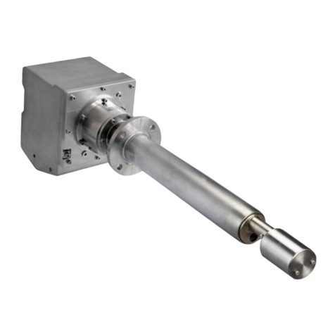
The CDM is a controller of dust emission based on
triboelectricity principle. It is directly installed on the pipe
and the sensor is in direct contact with the air flow and
particles.
The CDM controls in real time the dust emission rate and
warns if this rate becomes higher than the ALARM and
ALERT level, adjusted by the operator on site.
The CDM reports the status of ALARM and ALERT level on
contact toggle switch.
An interface of visualization allows the user to check the
efficient running of the CDM.
The display also shows the trend of dust emission in %
compared to the threshold ALARM.
No material is needed to adjust the probe CDM. All the
adjustments are done thanks to the user interface
integrated in the CDM.
When we install the probe, it is necessary to start a self-
learning of the mean dust emission rate (PR) in normal
running conditions, and we must adjust several thresholds
necessary to have a good running of the CDM:
-Value X: Value in minutes: during this time, the
CDM defines a mean value of the dust
emission rate, in Measure mode or in PR self-
learning mode. This mean rate is recalculated
every second.
-Value n1: this value concerns the adjustment of
the ALERT threshold.
Threshold ALERT= n1 x PR
-Value n2 : this value concerns the adjustment
of the ALARM threshold.
Threshold ALARM = n2 x PR
SUMMARY
GENERAL Page 2
MECHANICAL ASSEMBLY Page 3
ELECTRICAL CONNECTIONS Page 4
ADJUSTMENTS Page 5
THE DEVICE Page 7
DYSFUNCTION Page 9
CHARACTERISTICS Page 10
GENERAL INSTRUCTIONS Page 11
FOR SAFETY, ASSEMBLY,
COMMISSIONING AND
MAINTENANCE
WARRANTY Page 12
CERTIFICATE Page 12

CDM-Sensor –Dust Emission
Incident Detector
Notice Technique
FI 72.0401.0819E
Page 3 / 12 - 3 -Page 3 sur 12 - 3 - - 3 - - 3 - - 3 -
MECHANICAL ASSEMBLY
The sensor is directly fixed on the pipe to monitor, in the following conditions:
- Thread G1/2"
-placed on the straight part of the pipe, following the drawing underneath,
-on a metallic pipe linked to earth, we must have a continuity of earth between the sensor and the pipe,
-standard length of the probe: 220 mm for 250mm < pipe diameter < 1000mm
After consult if pipe diameter > 1000mm
On request if 100mm < pipe diameter < 250mm
Figure 1 : mechanical assembly
Figure 2: mechanical dimensions
ELECTRICAL CONNECTIONS
Version ATEX
Version ATEX

CDM-Sensor –Dust Emission
Incident Detector
Notice Technique
FI 72.0401.0819E
Page 4 / 12 - 4 -Page 4 sur 12 - 4 - - 4 - - 4 - - 4 -
ELECTRICAL CONNECTIONS
Use the cable supplied with the sensor CDM (cable length=3.5m)
Cable PVC Gray, 8x0.25mm² (AWG24), Diam. Ext 6.2mm
Connect the contacts (naked part) of the cable with the external process.
Warning:
- Connect the sensor to earth by the terminal which is on the body of the sensor.
- Check the electrical characteristics of the CDM before any connection to the process, to prevent any
damage to the CDM.
- We recommend shielded cables between the sensor and the COM RS485.
Figure 3 : list of contacts Gland Version
Contact
Couleur
Signal
1
Yellow
ALARM Contact 1
2
Green
ALARM Contact 2
3
Brown
ALERT Contact 1
4
White
ALERT Contact 2
5
Gray
RS485/B (-)
6
Pink
RS485/A (+)
7
Blue
GND
8
Red
VCC
Please isolate unused contacts individually in order to avoid short circuit,
may cause damage or malfunction of the equipment.

CDM-Sensor –Dust Emission
Incident Detector
Notice Technique
FI 72.0401.0819E
Page 5 / 12 - 5 -Page 5 sur 12 - 5 - - 5 - - 5 - - 5 -
ADJUSTMENTS
Self-learning of reference point (PR):
Value of the mean dust rate, in normal conditions of exploitation.
1/ Sensor in MEASURE mode
2/ Open the cover of the sensor, after taking off the screw –Cover opening
3/ Maintain « F » key until the bargraph starts to turn on as a chase.
4/ Close quickly the cover with the screw, in order not to disturb the measure by external environment (electromagnetic
wave). The self-learning will really start only start 10 seconds when the sensor is in self-learning mode.
5/ At the end of the self-learning, automatic transition to MEASURE MODE of the CDM.
Time of the self-learning: X threshold.
During the whole self-learning phase, we recommend that the installation is in normal running conditions.
Adjustment of the Value X (from 1 to 33 min):
Value in minutes. During this time the CDM defines a mean value of the dust rate, in MEASURE mode and
AUTOLEARNING mode of the PR. This mean value is recalculated each second.
1/ Sensor in MEASURE mode.
2/ Open the cap of the sensor by taking off the screw –cap opening.
3/ push the key « F » several times until the led X flashes.
Visualization of the adjustment value with the bargraph (see Board 2).
4/ Adjust the value X by pressing the button « + » until you get the expected value.
The adjusted value can only be increased. When the max value is reached, we go back to mini value.
5/ Automatic transition to MEASURE mode when no key is pressed during more than 5 seconds.
Adjustment of threshold n1 (from x2 to x33):
This value is used to adjust the value of the threshold ALERT: threshold ALERT= n1 x PR
1/ Sensor in MEASURE mode.
2/ Open the cap of the sensor by taking off the screw –cap opening.
3/ push the key « F » several times until the led n1 flashes.
Visualization of the adjustment value with the bargraph (see Board 2).
4/ Adjust the value n1 by pressing the key « + » until you get the expected value.
The adjusted value can only be increased. When the max value is reached, we go back to mini value.
5/ Automatic transition to MEASURE mode when no key is pressed during more than 5 seconds.
Adjustment of threshold n2 (from x2 to x33):
This value is used to adjust the value of the threshold ALARM: threshold ALARM= n2 x PR
1/ Sensor in MEASURE mode.
2/ Open the cap of the sensor by taking off the screw –cap opening.
3/ push the key « F » several times until the led n2 flashes.
Visualization of the adjustment value with the bargraph (see Board 2).
4/ Adjust the value n2 by pressing the key « + » until you get the expected value.
The adjusted value can only be increased. When the max value is reached, we go back to mini value.
5/ Automatic transition to MEASURE mode when no key is pressed during more than 5 seconds.

CDM-Sensor –Dust Emission
Incident Detector
Notice Technique
FI 72.0401.0819E
Page 6 / 12 - 6 -Page 6 sur 12 - 6 - - 6 - - 6 - - 6 -
Configuration of the running of signals ALARM and ALERT
Depending on the position of switches SEL1 and SEL2 (see drawing 4), the running of the signals ALARM and ALERT
present 4 modes:
Table 1 :
Mode
Switch
SEL1
Switch
SEL2
ALERT (contact open)
ALARM (contact open)
1*
Off
Off
If mean dust rate during X min. > n1 x PR
If mean dust rate during X min. > n2 x PR
2
Off
On
If instantaneous dust rate > n1 x PR
If mean dust rate during X min. > n2 x PR
3
On
Off
If instantaneous dust rate < n1 x PR
If mean dust rate during X min. > n2 x PR
4
On
On
if failure
If mean dust rate during X min. > n2 x PR
*: Value defined in our workshop.
Remarks:
In case of supply shutdown, the CDM doesn’t need to be adjusted again.
All the adjusted parameters are recorded.
The adjustments, which need the opening of the cover, must be done quickly. Don’t let the cover open when not
needed.
During the self-learning phase of the reference point, the top of the sensor must be closed.
Be sure that the cover is correctly closed after every opening of it.
To limit the electrostatic impact during the use of user interface, we recommend to the operator to wear an
electrostatic bracelet.

CDM-Sensor –Dust Emission
Incident Detector
Notice Technique
FI 72.0401.0819E
Page 7 / 12 - 7 -Page 7 sur 12 - 7 - - 7 - - 7 - - 7 -
THE DEVICE
User Interface
Figure 4 : user interface
Supply Led
Key F
Key +
ALERT Led
ALARM Led
PR/x LED
TST/n1 Led
MES/n2 Led
11 parts BARGRAPH (0 to 100%)
SEL1, SEL2

CDM-Sensor –Dust Emission
Incident Detector
Notice Technique
FI 72.0401.0819E
Page 8 / 12 - 8 -Page 8 sur 12 - 8 - - 8 - - 8 - - 8 -
Table 2 : Signification of Leds
Leds
Mode
State
Signification
ALERT
(Orange)
Measure
on
Contact ALERT opened (1)
off
Contact ALERT closed (1)
ALARM
(Red)
Measure
on
Contact ALARM opened (1)
off
Contact ALARM closed (1)
flashing
Failure (2)
BARGRAPH
(Blue)
Measure
on
Shows the trend of the dust emissions (mean value for each minute) in % of the adjusted
ALARM threshold : 100% = ALARM= PR x n2
If only the part 0% flashes => Measure < Value PR
If parts 0% to 90% are on and the part 100% flashes => Measure > Threshold ALARM
Adjustment PR
Daisy chain
If parts 0% to 100% on => PR< Measure < Threshold ALARM
Adjustment Value
x,thresholds n1, n2
Always on
Value1 = 3xNb parts always on
Slow flashing
Value = Value1 +1
Fast flashing
Value = Value1 +2
MES/ n2 (Vert)
Measure
on
CDM mode MEASURE
Adjustment n2
flashing
CDM mode ADJUSTMENT Threshold n2
TST/n1 (Vert)
Measure
on
CDM mode AUTOTEST
Adjustment n1
flashing
CDM mode ADJUSTMENT Threshold n1
PR/x (Vert)
Adjustment PR
on
CDM mode AUTOLEARNING PR
Adjustment x
flashing
CDM mode ADJUTMENT Value x
(1) : See conditions Board 1
(2) : See conditions Board 3
Examples :
Case n°1 :
Adjustments : n1=2 => Threshold ALERT = 2*PR
n2=5 => Threshold ALARM = 5*PR
x =5 => Average of measured dust rate during the last 5 minuts
If mean value of dust rate = 2.5*PR
Then Visu Bargraph = 2.5 / 5(n2) x100 = 50% : Relay ALARM Off
And Threshold ALERT < mean dust rate measure : Relay ALERT On
Case n°2 :
Adjustments : n1=2 => Threshold ALERT = 2*PR
n2=5 => Threshold ALARM = 5*PR
x =5 => Average of measured dust rate during the last 5 minuts
If mean value of dust rate = 1.5*PR
Then Visu Bargraph = 1.5 / 5(n2) x100 = 30% : Relay ALARM Off
And Threshold ALERT > mean dust rate measure : Relay ALERT Off

CDM-Sensor –Dust Emission
Incident Detector
Notice Technique
FI 72.0401.0819E
Page 9 / 12 - 9 -Page 9 sur 12 - 9 - - 9 - - 9 - - 9 -
FAILURE
The CDM regularly runs an AUTOTEST of its electronics, to check its efficiency.
If an internal failure is detected by the CDM, this one informs the user by the ALARM Led and the ALARM Relay.
Table 3 :
ALARME LED
Failure
Priority
Remark
Flashing 1x +
Pause
Internal T°C
5
Contact the supplier
Flashing 2x +
Pause
Electronics
4
Contact the supplier
Flashing 3x +
Pause
Saturation
3
Contact the supplier
Flashing 4x +
Pause
Threshold ALARM out of limits
Threshold ALERT out of limits
Threshold ALARM > Threshold ALERT
2
Modify the value n2
Modify the value n1
Modify the value n2 and/or n1
On
Dust Measure > Threshold ALARM
1
If several faults appear at the same time, it is the failure with the highest priority, which will be indicated by the ALARM Led
and Relay.

CDM-Sensor –Dust Emission
Incident Detector
Notice Technique
FI 72.0401.0819E
Page 10 / 12 - 10 -Page 10 sur 12 - 10 - - 10 - - 10 - - 10 -
CHARACTERISTICS
Supply 24VDC +/- 10%
Consumption 80mA max.
Relay ALERT / ALARM inverter contact 1A 30VDC / 0.3A 125VAC
Network type RS 485 maxi length < 1,2 km (depends on cable)
Link MODBUS Mode RTU
Speed 115200 Bauds / 8Bits / 1 Bit Start / 1 Bit Stop / No parity
MODBUS Table available on request
Adjustments parameters via User Interface Sensor CDM or via Com. MODBUS RS485
Device Protection via resettable fuse
Protection Level IP 65
Weight 600g
Measure interval From 0.1 mg/m3
Diameter Pipe Standard : from 250 to 1000mm
If Ø < 250mm : on request
If Ø > 1000mm : consult us
Running Temperature
- external part to the pipe, body of the CDM : -20°C to +60°C
- internal part to the pipe : flow < 150° (CDM standard)
Storage Temperature -20°C to +85°C
Material Body of the sensor : aluminium
Transparent window of the sensor: Polycarbonate
Body of the probe : Inox
PTFE for isolator
Version non ATEX : Polyamid gland
Version ATEX : Brass Nickel-plated gland
Cable Link Process Length 3.5m (8*AWG24)
Version ATEX see document TRIB’ATEX-CDM FI 72.0419.xxxx

CDM-Sensor –Dust Emission
Incident Detector
Notice Technique
FI 72.0401.0819E
Page 11 / 12 - 11 -Page 11 sur 12 - 11 - - 11 - - 11 - - 11 -
General instructions for safety, assembly, commissioning, usage and maintenance
to be read before working on the device
I. GENERAL
These instructions must be read jointly with:
+the standard NFC15-100
+the technical data sheet specific to the device
The Sefram devices are designed to be assembled,
commissioned and used in compliance with the
characteristics/data given in the technical data sheet.
Always adhere to all of directives, legislation, orders and
most recent standards in force for the stated field of
application.
The assembly, commissioning, usage and maintenance
operations must always be carried out by qualified and
authorised personnel.
Personnel working on the devices must be familiar with
the safety rules and requirements in force regarding the
components, devices, machines and electrical
installations.
II. RECEPTION - STORAGE
After unpacking the device, check that this latter has not
been damaged during transport; for certain devices,
remove the protective film from the cover. The material
must be stored inside in a dry place.
In the event of a problem, please contact Sefram.
III. ASSEMBLY
The assembly operations must be carried out by
qualified, skilled and authorised personnel. Personnel
working on these devices must be familiar with the
safety rules and requirements in force.
The box must be mounted vertically.
For material connected permanently to the network, a
quickly accessible cut-off device must be incorporated
into the cabling installation of the building.
The device supply must be equipped with a device for
protection against risks of over-current and fault
isolation. The number of poles protected must be
appropriate to the neutral regime of the building and to
the regulations in force.
The equipment must be connected to the PE protection
mass by green/yellow wires (NFC15-100).
The device is compatible with the neutral regimes TT,
TN or IT;
Nevertheless, we recommend that the device is
supplied through the intermediary of an insulation
transformer for which the primary is supplied between
phases and not between phase and neutral, so as to
avoid any accidental over-voltage caused when the
neutral is cut before the phases.
If question or problem during these operations,
please contact Sefram.
IV. COMMISSIONING AND USAGE
Commissioning is authorised only after duly establishing
that the device, the machine or the installation in which
the device has been integrated in a compliant manner,
satisfies all of the directives, legislation, orders and
most recent standards in force.
Commissioning operations must be carried out by
qualified, skilled and authorised personnel. Personnel
working on these devices must be familiar with the
safety rules and requirements in force.
Note: correct operational functioning does not in itself
constitute an indication of conformity to the
recommendations for the use of the material in
complete safety.
Also read the maintenance recommendations which
equally apply during commissioning and use.
In the event of a problem, please contact Sefram.
V. MAINTENANCE
The device does not require any special maintenance.
The following operations are recommended; they
constitute a minimum:
- Before any work intervention, we recommend
that the dust is removed before opening the
cover,
- The device must not be opened in an
excessively dusty environment,
- The settings must be carried out in the shortest
lapse of time so as not to engender any risks,
- The integrity of the joints must be checked:
remove any trace of dust or other deposit,
- Remove any trace of dust which could have
penetrated during the setting operation,
- Always ensure that the cover is correctly
closed.
- For high concentrations of "sticky / caking"
products, periodically clean the sensor which is
immersed in the flow.
- In the event of a major change appears on the
operating conditions may affect the baseline
rate of dust, make learning a new reference
point PR.
Maintenance operations must be carried out by
qualified, skilled and authorised personnel. Personnel
working on these devices must be familiar with the
safety rules and requirements in force.
N.B : Version ATEX →see instruction FI 72.0419

CDM-Sensor –Dust Emission
Incident Detector
Notice Technique
FI 72.0401.0819E
Page 12 / 12 - 12 -Page 12 sur 12 - 12 - - 12 - - 12 - - 12 -
WARRANTY:
The warranty does not apply in the following cases:
-Breakage through dropping or knocks to non-packaged products
-Damage caused by abnormal use of the device, connecting error, surges/overvoltages, etc.
-Any intervention on the device apart from the connections
Warranty and homologation of ATEX devices :
No intervention can be done on the deveice : this one must be sent back to our workshop. Otherwise, it may
loose its homologation and warranty.
In case of failure, no action is permitted and the unit must be returned to the following address:
CERTIFICATE
The CDM respects the European directives ( CEM and ATEX ), which concerns it.
However, it must be used correctly in applications for which it is intended, and should be linked or near CE approved
products.
Certificate available on request.
SEFRAM
PLACE GUTENBERG
59175 TEMPLEMARS
Table of contents
Other SEFRAM Measuring Instrument manuals
SEFRAM
SEFRAM BK Precision DAS30 User manual
SEFRAM
SEFRAM 87 User manual
SEFRAM
SEFRAM DAS240 User manual
SEFRAM
SEFRAM M9885A00 User manual
SEFRAM
SEFRAM MW 3950 User manual
SEFRAM
SEFRAM 7880 User manual
SEFRAM
SEFRAM MW3366 User manual
SEFRAM
SEFRAM 52 User manual
SEFRAM
SEFRAM 7859 User manual
SEFRAM
SEFRAM MW 3352 User manual
SEFRAM
SEFRAM 7940 Series User manual

SEFRAM
SEFRAM 3526BF User manual

SEFRAM
SEFRAM DAS220BAT User manual
SEFRAM
SEFRAM DAS240BAT User manual
SEFRAM
SEFRAM 9836 User manual
SEFRAM
SEFRAM 3515F User manual

SEFRAM
SEFRAM MW3518 User manual
SEFRAM
SEFRAM MW3036 User manual
SEFRAM
SEFRAM MW3027 User manual
SEFRAM
SEFRAM 7805B User manual
