10/24
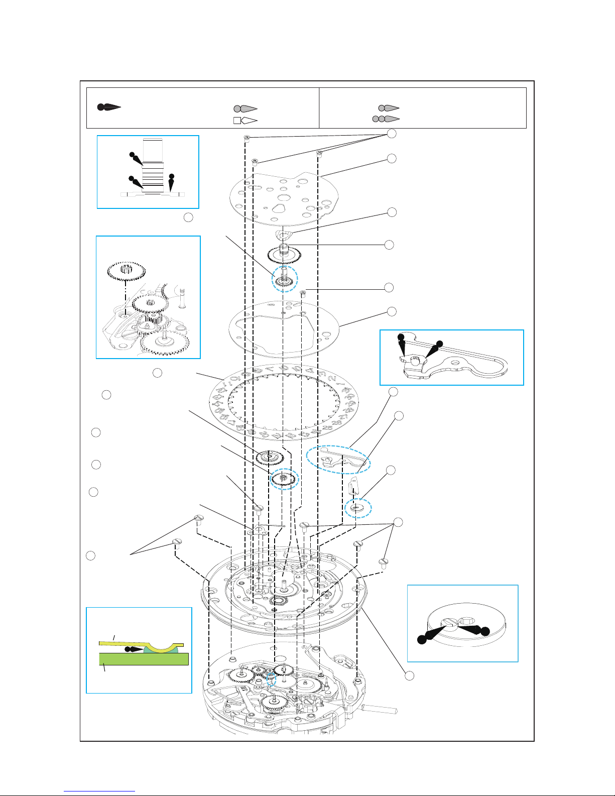
● List of screw
Parts code Parts name Parts code Parts name Parts code Parts name
0012 092 Second counting wheel
spring screw
0012 354 Unit intermediate
spacer screw
0012 420 Balance bridge
screw
Chronograph bridge
screw (x5)
Pallet bridge screw
(x2)
Barrel and train
wheel bridge
screw (x3)
Operation lever spring
screw Automatic train
bridge screw (x2)
0012 168
Yoke spring screw
(x2)
Operation cam jumper
screw
Lower plate for barrel
and train wheel bridge
screw
Chronograph coupling
lever spring screw
Center wheel bridge
screw
Main plate screw (x4) 0012 201
Operatig cam screw
0016 709 Hour wheel guard
screw (x3)
0012 919
Ratchet wheel screw
Date indicator
maintaining plate
screw
59
69
85
45
79
75
64
61
49
15
17
33
36
38
58
67
2
7
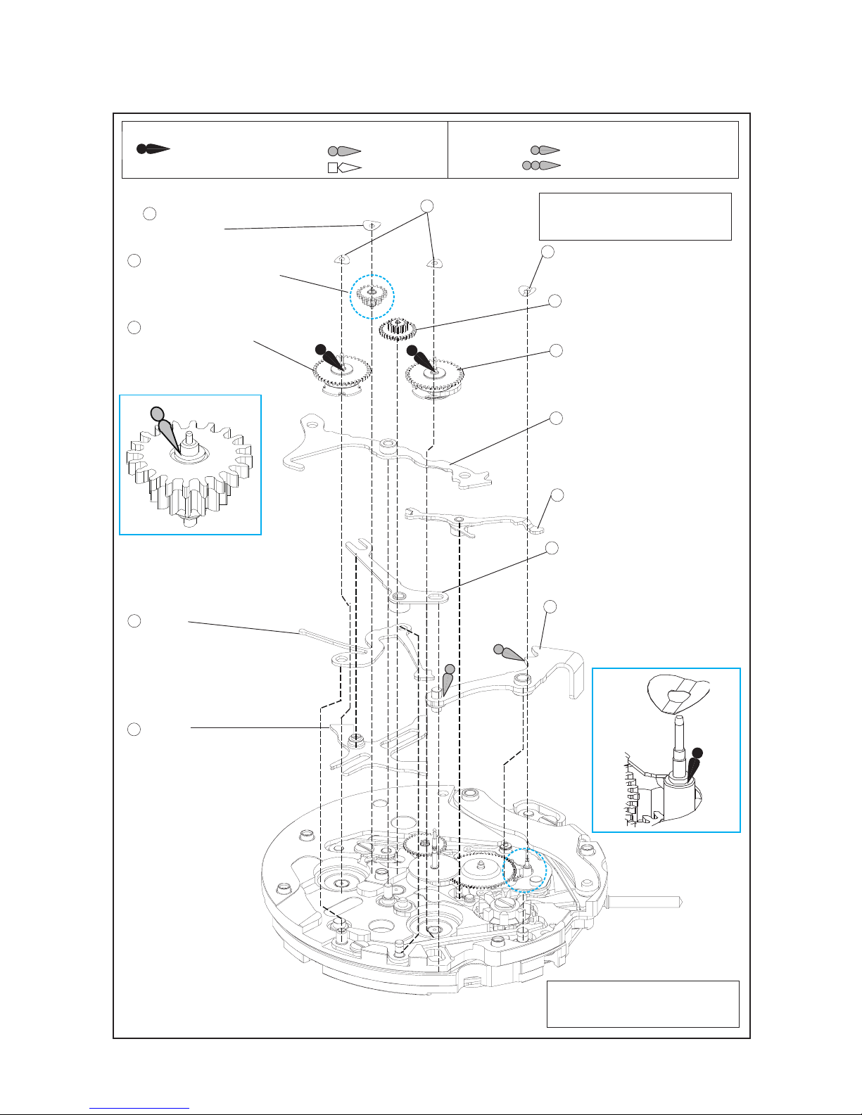
Date dial
9
Parts code Position of crown Position of date
frame Color of numbers Color of background
0878 109 3H 3H Black Silver
(Plain metal)
0878 108 3H 3H White Black
● How to find the correct parts, if not determined by 4 digit caliber number
*All parts code are subject to change without notice.
Following parts are determined based on the design of watches, such as hands height, dial color,
and design of cases. Please refer to the SEIKO WATCH PARTS CATALOGUE in order to choose
corresponding parts.
Oscillating weight with ball bearing 0509 *** • 1509 ***
DATE DISK 0878 ***
WINDING STEM 0351200
*For screw down crown models, the stem is assembled to the crown and is not available separately.
1
9
90
CAL Hand Height 18 Chronograph
bridge
19 Minute counting wheel
20 Hour counting wheel
44 Seconds
wheel
60-1 Balance
complete without
stud
8R48 3 (LONG) 0190192 0902184 0240178 0310055
4 (SPECIAL) 0190193 0902191 0240191
8R49 3 (LONG) 0190192 0902184 0240178 0310277
18
Chronograph bridge 0190 ***
24
Minute counting wheel 0902 ***
25
Hour counting wheel 0902 ***
44
Seconds wheel 0240 ***
60 -1 Balance complete without stud 0310 ***