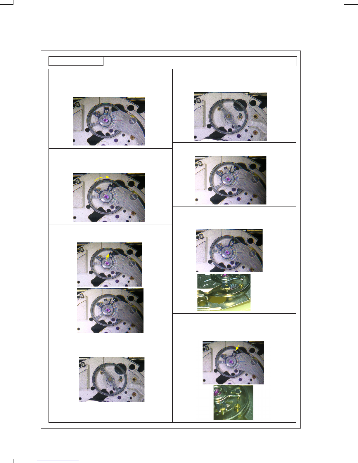
How to remove How to install
1. Initial phase
Set the balance complete with stud and balance bridge
to the main plate.
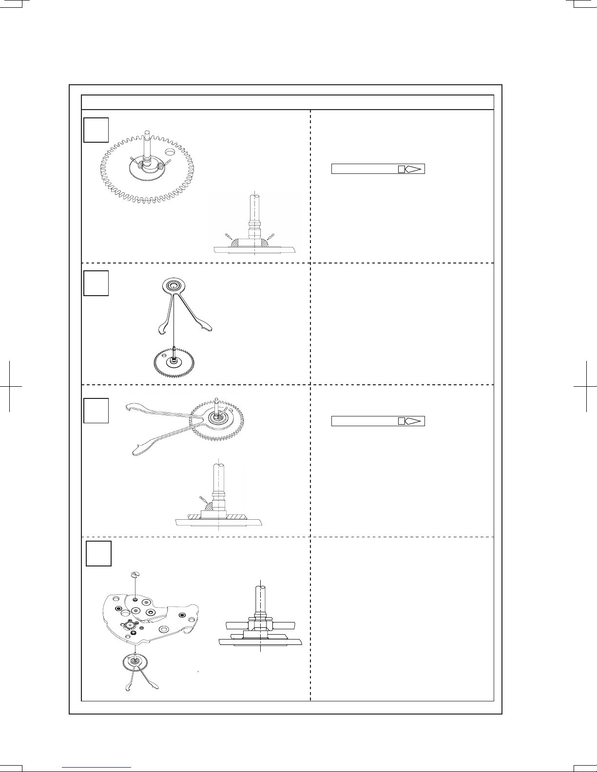
PREPARATION
HOW TO REMOVE AND INSTALL THE BALANCE STAFF
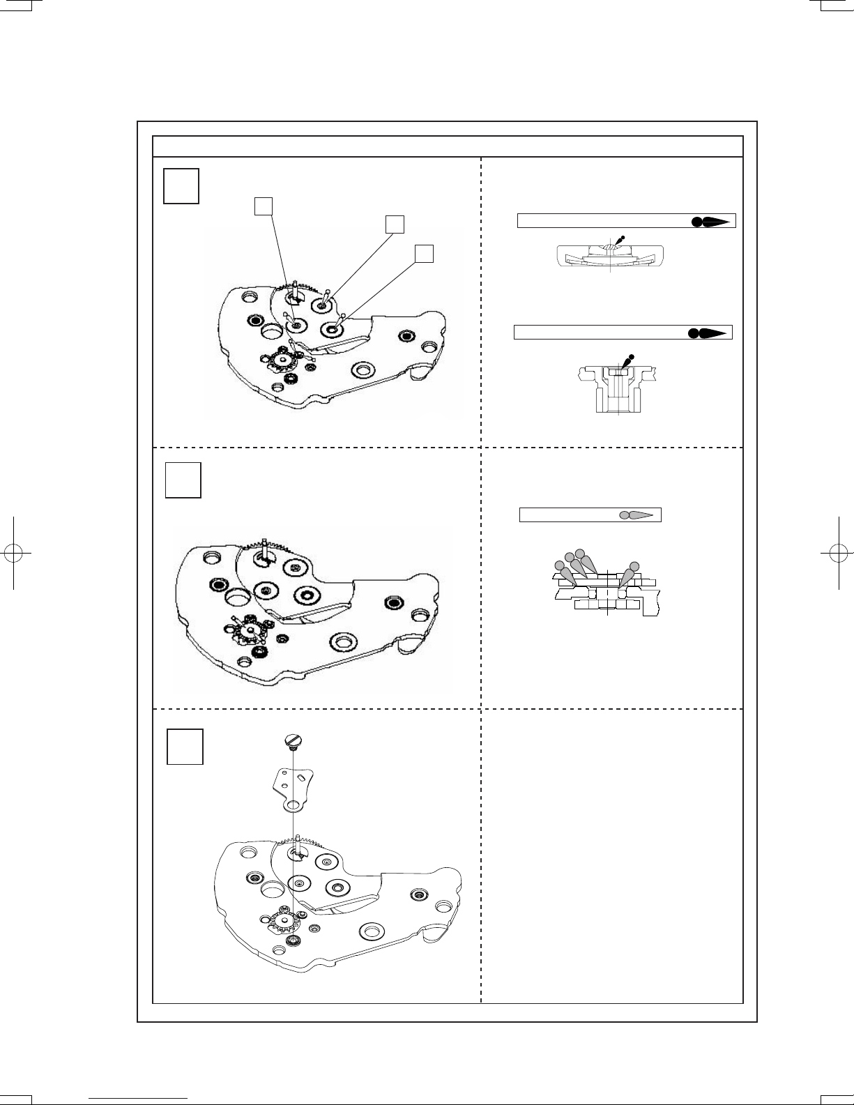
2. Move the stud support toward the balance bridge until it
is attached to the balance bridge.
* When doing so, make sure that the outer end of the
hairspring is not removed from the regulator arm.
4. Remove the balance bridge and replace the balance
complete with stud with a new one.
3. Temporarily set the stud to the stud support.
Make sure that the hairspring passes outside the pin of
the regulator arm.
* Be careful not to damage the hairspring.
1. Initial phase
Set a new balance complete with stud to the main plate.
2. Set the balance bridge and tighten the balance bridge
screw.
4. Using sturdy tweezers, set the stud to the stud support
and press it down.
Make sure that the outer end of the hairspring passes
through the regulator slot of the regulator arm.
* Be careful not to damage the hairspring.
3. Using sturdy tweezers, push the stud outward from the
direction of the arrow shown in the illustration until it is
removed from the stud support.
TECHNICAL GUIDE Cal. 6R20A
6/24